Configuring Integrated IS-IS
| Integrated IS-IS is unique among the IP routing protocols covered in this book for two reasons. First, it is the only IP routing protocol that must be enabled both as a process and on individual interfaces. Second, it is the only IP routing protocol that was not originally designed for IP. Because IS-IS uses CLNS PDUs rather than IP packets, the configuration is not always as obvious as that of the other protocols. Case Study: A Basic IPv4 Integrated IS-IS ConfigurationA basic Integrated IS-IS process is configured on a Cisco router in four steps:
Figure 10-51 shows a small six-router network divided into two areas. In the NETs, areas 1 and 2 will be encoded as 00.0001 and 00.0002, respectively, and the System IDs will be the MAC identifiers of the E0 or FastEthernet0/0 interfaces of each router. Table 10-6 shows the NETs encoded with this information. Figure 10-51. Area 1 is encoded as 00.0001 in the NET, and area 2 is encoded as 00.0002. The System ID of each NET is the E0 or TO0 MAC identifier.
The configurations of Paris, London, Brussels, and Amsterdam are displayed in Example 10-9 through Example 10-12. Example 10-9. Paris.interface Serial0/0.1 point-to-point ip address 10.1.255.5 255.255.255.252 ip router isis ! interface FastEthernet0/0 ip address 10.1.2.1 255.255.255.0 ip router isis ! interface FastEthernet0/1 ip address 10.1.7.1 255.255.255.0 ip router isis ! router isis net 00.0001.0004.c150.e700.00 Example 10-10. London.interface Ethernet0/0 ip address 10.1.3.2 255.255.255.0 ip router isis ! interface Serial0/0.1 point-to-point ip address 10.1.255.6 255.255.255.252 ip router isis ! router isis net 00.0001.00b0.6430.1de0.00 Example 10-11. Brussels.interface FastEthernet0/0 ip address 10.1.3.1 255.255.255.0 ip router isis ! interface FastEthernet0/1 ip address 10.1.4.1 255.255.255.0 ip router isis ! router isis net 00.0002.0005.5e6b.50a0.00 Example 10-12. Amsterdam.clns routing ! interface FastEthernet0/0 ip address 10.1.4.2 255.255.255.0 ip router isis ! interface FastEthernet0/1 ip address 10.1.5.1 255.255.255.0 ip router isis ! interface FastEthernet0/2 ip address 10.1.6.241 255.255.255.240 ip router isis ! router isis net 00.0002.0000.0c8d.34f1.00 The configurations of Berlin and Rome are similar. A detail that you should notice is that CLNS routing is enabled in Amsterdam's configuration. The CLNS routing is necessary to handle the CLNS PDUs used by IS-IS. CLNS routing is enabled automatically when you create an IS-IS process. In some versions of IOS, you might see the clns routing command in the configuration, even though it is not required to enter it as a configuration step. Example 10-13 shows Paris's route table. Notice that the table contains both L1 and L2 routes. By default, Cisco routers are L1/L2 routers. This fact is also apparent by observing the routers' IS neighbor tables, as in Example 10-14. Example 10-13. Paris's route table shows both L1 and L2 routes, indicating that this router is an L1/L2 router.Paris#show ip route Codes: C - connected, S - static, R - RIP, M - mobile, B BGP D - EIGRP, EX - EIGRP external, O - OSPF, IA - OSPF inter area N1 - OSPF NSSA external type 1, N2 - OSPF NSSA external type 2 E1 - OSPF external type 1, E2 - OSPF external type 2 i - IS-IS, su - IS-IS summary, L1 - IS-IS level-1, L2 - IS-IS level-2 ia - IS-IS inter area, * - candidate default, U - per-user static route o - ODR, P - periodic downloaded static route Gateway of last resort is not set 10.0.0.0/8 is variably subnetted, 9 subnets, 3 masks i L1 10.1.8.0/24 [115/20] via 10.1.2.2, FastEthernet0/0 i L1 10.1.3.0/24 [115/20] via 10.1.255.6, Serial0/0.1 C 10.1.2.0/24 is directly connected, FastEthernet0/0 C 10.1.7.0/24 is directly connected, FastEthernet0/1 i L2 10.1.5.0/24 [115/40] via 10.1.255.6, Serial0/0.1 i L2 10.1.4.0/24 [115/30] via 10.1.255.6, Serial0/0.1 C 10.1.255.4/30 is directly connected, Serial0/0.1 i L1 10.1.255.8/30 [115/20] via 10.1.2.2, FastEthernet0/0 i L2 10.1.6.240/28 [115/40] via 10.1.255.6, Serial0/0.1 Paris#Example 10-14. Berlin's IS neighbor table shows that both Paris and Rome are L1/L2 routers.Berlin#show clns is-neighbors System Id Interface State Type Priority Circuit Id Format Rome Se0.1 Up L1L2 0 /0 00 Phase V Paris Et0 Up L1L2 64/64 Berlin.01 Phase V Berlin#Notice in Berlin's IS neighbor table that the name of each neighbor is listed. Hostnames are dynamically exchanged using the TLV type 137, as discussed in the section "Dynamic Hostname Exchange." To view the system identifiers associated with each hostname, use the command show isis hostname, as displayed in Example 10-15. Example 10-15. The system IDs associated with known hostnames are displayed using the command show isis hostname.Berlin#show isis hostname Level System ID Dynamic Hostname (notag) 1 00B0.6430.1DE0 London 2 0000.0C8D.34F1 Amsterdam 1 0004.C150.E700 Paris 1 0004.C150.F1C0 Rome * 0010.7B3C.6BD3 Berlin Berlin#Because every router in the network of Figure 10-51 is an L1/L2, every router has formed both L1 adjacencies and L2 adjacencies. Consequently, every router has both an L1 and an L2 LS database. The L1 areas completely overlap with the L2 area. For example, Example 10-16 shows the LS databases of Amsterdam. The L1 database contains an LSP originated by Amsterdam[23] and an LSP originated by Brussels. It also contains a pseudonode LSP (Brussels.02-00) originated by Brussels, representing the Ethernet link between Brussels and Amsterdam. Remember that the LSP ID is recognizable as that of a pseudonode LSP because the next-to-last octet, the Pseudonode ID, is non-zero.
Example 10-16. Amsterdam has both a level 1 LS database and a level 2 LS database, indicating that the router is an L1/L2 router.Amsterdam#show isis database IS-IS Level-1 Link State Database: LSPID LSP Seq Num LSP Checksum LSP Holdtime ATT/P/OL Amsterdam.00-00 * 0x00000015 0x642E 1112 1/0/0 Brussels.00-00 0x00000016 0x9B81 1187 1/0/0 Brussels.02-00 0x00000013 0x46BD 1139 0/0/0 IS-IS Level-2 Link State Database: LSPID LSP Seq Num LSP Checksum LSP Holdtime ATT/P/OL Amsterdam.00-00 * 0x00000015 0xEAFF 1176 0/0/0 Paris.00-00 0x00000023 0x2B29 504 0/0/0 Rome.00-00 0x0000001D 0xD016 482 0/0/0 Brussels.00-00 0x00000019 0x45BB 1187 0/0/0 Brussels.02-00 0x00000013 0xD5B6 375 0/0/0 Berlin.00-00 0x0000001E 0x408B 506 0/0/0 Berlin.01-00 0x00000013 0xB10F 557 0/0/0 London.00-00 0x00000019 0xF1B1 463 0/0/0 London.01-00 0x00000013 0x9E92 844 0/0/0 Amsterdam#The three level-1 LSPs indicate that, other then Amsterdam, the only L1 router known to Amsterdam is Brussels. This single node is expected because Brussels is the only other router in area 2. Amsterdam's L2 database shows that Amsterdam knows of every router in the IS-IS domain, which is also expected because every router is an L1/L2. Case Study: Changing the Router TypesIn a small network like the one in Figure 10-51, leaving all routers at their default type is acceptable. As the network grows, these defaults become less and less acceptable. Not only is the processing and maintenance of two LS databases a burden on the router's CPU and memory, the L1 and L2 IS-IS PDUs being originated by every router become a burden on the buffers and bandwidth. Paris, Berlin, and Amsterdam in Figure 10-51 can be configured as L1 routers, because they have no direct connection to another area. To change the default router type, use the command is-type. For example, to make Berlin an L1 router, its configuration is as displayed in Example 10-17. Example 10-17. Berlin is configured to be a L1 router.router isis net 00.0001.0000.3090.c7df.00 is-type level-1 Paris and Amsterdam are configured similarly. Comparing Paris's route table in Example 10-18 with its route table in Example 10-13 shows that the L2 routes have been deleted. Similarly, comparing Example 10-19 with Example 10-16 shows that Amsterdam now has only an L1 LS database. Example 10-18. After Paris is configured as an L1 router, its route table contains routes only to destinations within its own area.Paris#show ip route Codes: C - connected, S - static, R - RIP, M - mobile, B BGP D - EIGRP, EX - EIGRP external, O - OSPF, IA - OSPF inter area N1 - OSPF NSSA external type 1, N2 - OSPF NSSA external type 2 E1 - OSPF external type 1, E2 - OSPF external type 2 i - IS-IS, su - IS-IS summary, L1 - IS-IS level-1, L2 - IS-IS level-2 ia - IS-IS inter area, * - candidate default, U - per-user static route o - ODR, P - periodic downloaded static route Gateway of last resort is 10.1.255.6 to network 0.0.0.0 10.0.0.0/8 is variably subnetted, 6 subnets, 2 masks i L1 10.1.8.0/24 [115/20] via 10.1.2.2, FastEthernet0/0 i L1 10.1.3.0/24 [115/20] via 10.1.255.6, Serial0/0.1 C 10.1.2.0/24 is directly connected, FastEthernet0/0 C 10.1.7.0/24 is directly connected, FastEthernet0/1 C 10.1.255.4/30 is directly connected, Serial0/0.1 i L1 10.1.255.8/30 [115/20] via 10.1.2.2, FastEthernet0/0 i*L1 0.0.0.0/0 [115/10] via 10.1.255.6, Serial0/0.1 Paris#Example 10-19. After Amsterdam is configured as an L1 router, it has only a level 1 link-state database.Amsterdam#show isis database IS-IS Level-1 Link State Database: LSPID LSP Seq Num LSP Checksum LSP Holdtime ATT/P/OL Amsterdam.00-00 * 0x00000017 0x5644 1065 0/0/0 Brussels.00-00 0x00000018 0x9783 1063 1/0/0 Brussels.02-00 0x00000014 0x44BE 1063 0/0/0 Amsterdam#Recall from the earlier discussion of the ATT bit in the LSPs that an L1/L2 router uses the ATT bit to tell L1 routers that it has an inter-area connection. Example 10-20 shows that both London's LSP and Rome's LSP have ATT = 1. So Paris should know to send inter-area traffic to either London or Rome. In other words, Paris should have a default route to London or Rome, with London being preferred because it is metrically closer. Example 10-18 shows that there is a default route (0.0.0.0) in Paris's route table. Example 10-20. The L1 LSPs of London and Rome have ATT = 1, indicating a connection to another area.Paris#show isis database IS-IS Level-1 Link State Database: LSPID LSP Seq Num LSP Checksum LSP Holdtime ATT/P/OL Paris.00-00 * 0x00000022 0xA4C8 857 0/0/0 Rome.00-00 0x00000018 0x139F 727 1/0/0 Berlin.00-00 0x0000001C 0x28B8 733 0/0/0 Berlin.01-00 0x00000018 0x161F 851 0/0/0 London.00-00 0x00000017 0xDD92 848 1/0/0 London.01-00 0x00000014 0x9F54 1080 0/0/0 Paris#In older versions of IOS, the IP process does not directly interpret the ATT bit. The ATT bit is a CLNS function. When running older versions of IOS, if no default route is automatically created in the L1 routers, there are two solutions to the problem. The first solution is to enable IS-IS for CLNS on the interfaces in addition to IS-IS for IP. For example, the serial interface configurations for London and Paris are displayed in Example 10-21 and Example 10-22. Example 10-21. London is configured with IS-IS for CLNS on the interface to enable processing of the ATT bit.interface Serial0/0.1 ip address 10.1.255.6 255.255.255.252 ip router isis clns router isis Example 10-22. Paris is configured with IS-IS for CLNS on the interface to enable processing of the ATT bit.interface Serial0/0.1 ip address 10.1.255.5 255.255.255.252 ip router isis clns router isis This first solution works in a dual CLNP/IP environment, but if IS-IS is being used as an IP-only routing protocol, enabling CLNS routing just for default IP routes might be undesirable. A second solution to the default route problem is to configure a static default route on the L1/L2 router and configure IS-IS to advertise the default with the command default-information originate. Using this method in area 2 of Figure 10-51, the Brussels' configuration is displayed in Example 10-23. Example 10-23. Brussels is configured to originate a default route.router isis net 00.0002.0000.0c76.5b7c.00 default-information originate ! ip route 0.0.0.0 0.0.0.0 Null0 Default routes and the default-information originate command are discussed in more detail in Chapter 12, "Default Routes and On-Demand Routing." Case Study: An Area MigrationTo change area addresses in an OSPF domain, downtime must be scheduled. However, IS-IS is designed to allow areas to be changed nondisruptively. As discussed in "Operation of Integrated IS-IS," Cisco routers can be configured with up to 254 L1 area addresses. For two routers to form an L1 adjacency, they must have at least one area address in common. With multiple area addresses allowed, a new adjacency can take over while an old adjacency is being broken. This approach is useful when areas are being consolidated or split, when an area is being renumbered, or when area addresses assigned by multiple addressing authorities are being used in the same IS-IS domain. For example, the routers in Figure 10-52(a) all have an area address of 01. (A NET of one of these routers would look like 01.0000.0c12.3456.00.) In Figure 10-52(b), the routers have been assigned an additional area address of 03. Although multiple adjacencies are not actually formed, the routers do recognize that they have multiple area addresses in common. In Figure 10-52(c), area 01 has been removed from one of the routers. All three routers remain adjacent, because they all have at least one area address in common. Finally, in Figure 10-52(d), all of the 01 area addresses have been removed and the routers are all in area 03. At no time during the area migration was an adjacency lost. Figure 10-52. The support of multiple area addresses per router eases area changes.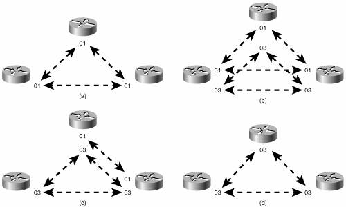 Suppose that the "powers that be" over the network in Figure 10-51 decree that the area addressing scheme being used is inappropriate and should become GOSIP compliant. After registering with the U.S. GSA, the following components are to be used to construct the NETs:
The new NETs are shown in Table 10-7.
The first step in changing the area addresses is to add the new NETs to the routers without changing the old NETs. Rome's IS-IS configuration is shown in Example 10-24. Example 10-24. Rome is configured with two NETs during transition.router isis net 00.0001.0000.0c0a.2aa9.00 net 47.0005.8000.ab7c.0000.ffe9.0001.0004.c150.f1c0.00 The other five routers are configured similarly. The results can be observed by using the detail keyword with either the show isis database command (Example 10-25) or the show clns is-neighbors command (Example 10-26). In both databases, multiple areas are associated with each router in the network. Example 10-25. The LSPs in Rome's link-state database show that all routers in the network of Figure 10-41 are advertising two area addresses.Rome#show isis database detail IS-IS Level-1 Link State Database: LSPID LSP Seq Num LSP Checksum LSP Holdtime ATT/P/OL Paris.00-00 0x00000026 0xC3AA 886 0/0/0 Area Address: 00.0001 Area Address: 47.0005.8000.ab7c.0000.ffe9.0001 NLPID: 0xCC Hostname: Paris IP Address: 10.1.7.1 Metric: 10 IP 10.1.2.0 255.255.255.0 Metric: 10 IP 10.1.255.4 255.255.255.252 Metric: 10 IP 10.1.7.0 255.255.255.0 Metric: 10 IS Berlin.01 Metric: 10 IS London.00 Rome.00-00 * 0x0000001E 0x4D64 688 1/0/0 Area Address: 00.0001 Area Address: 47.0005.8000.ab7c.0000.ffe9.0001 NLPID: 0xCC Hostname: Rome IP Address: 10.1.255.10 Metric: 10 IP 10.1.3.0 255.255.255.0 Metric: 10 IP 10.1.255.8 255.255.255.252 Metric: 10 IS Berlin.00 Metric: 10 IS London.01 Berlin.00-00 0x00000024 0xC419 716 0/0/0 Area Address: 00.0001 Area Address: 47.0005.8000.ab7c.0000.ffe9.0001 NLPID: 0xCC Hostname: Berlin IP Address: 10.1.8.1 Metric: 10 IP 10.1.2.0 255.255.255.0 Metric: 10 IP 10.1.8.0 255.255.255.0 Metric: 10 IP 10.1.255.8 255.255.255.252 Metric: 10 IS Berlin.01 Metric: 10 IS Berlin.02 Metric: 10 IS Rome.00 Berlin.01-00 0x0000001B 0x1022 572 0/0/0 Metric: 0 IS Berlin.00 Metric: 0 IS Paris.00 London.00-00 0x0000001A 0x1959 1044 1/0/0 Area Address: 00.0001 --More Example 10-26. Rome's IS-IS neighbor table also shows multiple addresses associated with each neighbor.Rome#show clns is-neighbors detail System Id Interface State Type Priority Circuit Id Format Berlin Se0/0.1 Up L1 0 00 Phase V Area Address(es): 00.0001 47.0005.8000.ab7c.0000.ffe9.0001 IP Address(es): 10.1.255.9* Uptime: 00:30:49 London Fa0/0 Up L1L2 64/64 London.01 Phase V Area Address(es): 00.0001 47.0005.8000.ab7c.0000.ffe9.0001 IP Address(es): 10.1.3.2* Uptime: 04:49:01 NSF capable Brussels Fa0/0 Up L2 64 London.01 Phase V Area Address(es): 00.0002 47.0005.8000.ab7c.0000.ffe9.0002 IP Address(es): 10.1.3.1* Uptime: 04:51:46 NSF capable Rome# The last step of the migration is to delete the old NET statements from all routers. For example, under Rome's IS-IS configuration the command no net 00.0001.0004.c150.f1c0.00 is entered. Example 10-27 shows some of the LSPs in Rome's database after the old NET statements have been removed from the routers. Example 10-27. The LSPs in Rome's database show only a single area address.Rome#show isis data detail IS-IS Level-1 Link State Database: LSPID LSP Seq Num LSP Checksum LSP Holdtime ATT/P/OL Paris.00-00 0x0000002D 0x412E 1171 0/0/0 Area Address: 47.0005.8000.ab7c.0000.ffe9.0001 NLPID: 0xCC Hostname: Paris IP Address: 10.1.7.1 Metric: 10 IP 10.1.2.0 255.255.255.0 Metric: 10 IP 10.1.255.4 255.255.255.252 Metric: 10 IP 10.1.7.0 255.255.255.0 Metric: 10 IS Berlin.01 Metric: 10 IS London.00 Rome.00-00 * 0x00000025 0x0BA7 1174 1/0/0 Area Address: 47.0005.8000.ab7c.0000.ffe9.0001 NLPID: 0xCC Hostname: Rome IP Address: 10.1.255.10 Metric: 10 IP 10.1.3.0 255.255.255.0 Metric: 10 IP 10.1.255.8 255.255.255.252 Metric: 10 IS Berlin.00 Metric: 10 IS London.01 Berlin.00-00 0x00000029 0x20C0 1097 0/0/0 Area Address: 47.0005.8000.ab7c.0000.ffe9.0001 NLPID: 0xCC Hostname: Berlin IP Address: 10.1.8.1 Metric: 10 IP 10.1.2.0 255.255.255.0 Metric: 10 IP 10.1.8.0 255.255.255.0 Metric: 10 IP 10.1.255.8 255.255.255.252 Metric: 10 IS Berlin.01 Metric: 10 IS Berlin.02 Metric: 10 IS Rome.00 Berlin.01-00 0x0000001D 0x0C24 1090 0/0/0 Metric: 0 IS Berlin.00 Metric: 0 IS Paris.00 London.00-00 0x0000001F 0xB7BD 1163 1/0/0 Area Address: 47.0005.8000.ab7c.0000.ffe9.0001 NLPID: 0xCC --More Case Study: Route SummarizationRoute summarization between areas in a link-state protocol is introduced in Chapter 8. A more complete discussion of summarization, in the context of default routes, is presented in Chapter 12. Briefly, summary routes are useful because
The primary disadvantages of summary routes are
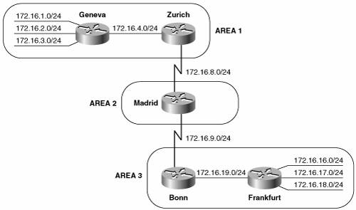
Summarization is enabled under the IS-IS configuration with the summary-address command. Any more-specific destination addresses that fall within the summarization range are suppressed, and the metric of the summary route is the smallest metric of all the more-specific addresses. Figure 10-53 shows an IS-IS network with three areas. The addresses within area 1 can be summarized with 172.16.0.0/21, and the addresses within area 3 can be summarized with 172.16.16.0/21. The configurations of Zurich, Madrid, and Bonn are displayed in Example 10-28 through Example 10-30.[24]
Figure 10-53. Zurich and Bonn are summarizing areas 1 and 3 into area 2. Example 10-28. Zurich is configured to perform route summarization.router isis net 01.0000.0c76.5b7c.00 summary-address 172.16.0.0 255.255.248.0 Example 10-29. Madrid's configuration has no route summarization.router isis net 02.0000.3090.6756.00 is-type level-2-only Example 10-30. Bonn is configured to perform route summarization.router isis net 03.0000.0c0a.2aa9.00 summary-address 172.16.16.0 255.255.248.0 Notice that Madrid, which has no L1 neighbors, is configured as an L2 router. Zurich and Bonn are summarizing their areas into the level 2 backbone. The results of the summarization can be seen in Madrid's route table (Example 10-31). Example 10-31. Madrid's route table shows the summary addresses advertised by Bonn and Zurich.Madrid#show ip route Codes: C - connected, S - static, R - RIP, M - mobile, B - BGP D - EIGRP, EX - EIGRP external, O - OSPF, IA - OSPF inter area N1 - OSPF NSSA external type 1, N2 - OSPF NSSA external type 2 E1 - OSPF external type 1, E2 - OSPF external type 2 i - IS-IS, su - IS-IS summary, L1 - IS-IS level-1, L2 - IS-IS level-2 ia - IS-IS inter area, * - candidate default, U - per-user static route o - ODR, P - periodic downloaded static route Gateway of last resort is not set 172.16.0.0/16 is variably subnetted, 4 subnets, 2 masks i L2 172.16.16.0/21 [115/20] via 172.16.9.2, Serial0/0.2 C 172.16.8.0/24 is directly connected, Serial0/0.1 C 172.16.9.0/24 is directly connected, Serial0/0.2 i L2 172.16.0.0/21 [115/20] via 172.16.8.2, Serial0/0.1 Madrid#Case Study: AuthenticationIS-IS authentication can use cleartext passwords or HMAC-MD5. There are two methods of configuring cleartext password. Both provide weak security against a determined attack on the network but are effective for preventing service disruptions from misconfigured or unauthorized routers. One of the cleartext configuration modes uses key chains, which can be encrypted in the configuration file so that someone cannot inadvertently obtain the password by looking at the file. Cleartext authentication without key chains is considered the "old style" password. Cisco IOS supports IS-IS authentication on three levels: between neighbors, area-wide, and domain-wide. The three authentication levels can be used by themselves or together. The rules for IS-IS authentication are
The steps for configuring authentication are the same as for RIPv2 and EIGRP. These steps are repeated here:
Authentication can be configured in the network without breaking adjacencies between routers. To accomplish this, the command isis authentication send-only must first be applied to all routers that will use authentication. This command is used on the interfaces to authenticate between neighbors and it is used under the ISIS routing process to authenticate area-wide or domain-wide. The command is removed after authentication is fully configured. To authenticate between neighbors, the key chain is configured, the isis authentication key-chain command references the preconfigured key chain, then the isis authentication mode command is used to configure the type of authentication on the connected interfaces. L1 and L2 adjacencies may reference different key chains. Neighboring routers must share a common key-string or password. The key chains for either or both levels can be specified on an interface, and the key-strings for each level can be the same or different. When configured, the key-strings are carried in authentication information TLVs in the L1 or L2 Hellos between IS-IS neighbors. For example, to authenticate between Geneva, Zurich, and Madrid in Figure 10-53, the configurations are as displayed in Example 10-32 through Example 10-34. Example 10-32. Geneva's authentication configuration.interface FastEthernet0/0 ip address 172.16.4.1 255.255.255.0 ip router isis isis password magic Example 10-33. Zurich's authentication configuration.key chain troll key 1 key-string magic key chain fairy key 1 key-string dust interface Ethernet0/0 ip address 172.16.4.2 255.255.255.0 ip router isis isis authentication mode text isis authentication key-chain troll level-1 ! interface Serial0/0.1 point-to-point ip address 172.16.8.2 255.255.255.0 ip router isis isis authentication mode text isis authentication key-chain fairy level-2 Example 10-34. Madrid's authentication configuration.key chain fairy key 1 key-string dust interface Serial0/0.1 point-to-point ip address 172.16.8.1 255.255.255.0 ip router isis isis authentication mode text isis authentication key-chain fairy level-2 Since the adjacency between Geneva and Zurich is L1, only a level 1 key-chain reference is specified. Between Zurich and Madrid, only an L2 adjacency exists, so a level 2 key-chain reference is used. Note that if no level-1 or level-2 keyword is specified, the isis password, isis authentication mode and isis authentication key-chain commands default to both L1 and L2. Note Geneva's configuration. Geneva's interface connecting to Zurich is configured with the old style cleartext password. The password must be the same as the key-string defined on Zurich for the adjacencies to establish.[25]
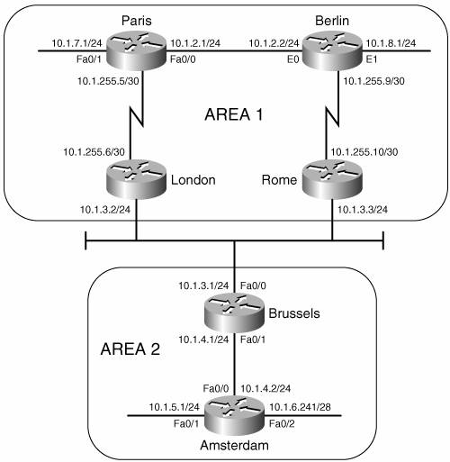
To authenticate within an area, the isis authentication mode mode level-1 and isis authentication key-chain name level-1 commands are used to define the authentication mode and to reference a key chain under the IS-IS configuration. When the mode is text, the two commands together are used in place of the old style area-password command. Whereas the key-string specified at the interface level by the isis authentication command is carried in Hellos, the key-string specified by the level-1 authentication command for the IS-IS process is carried in all L1 LSPs, CSNPs, and PSNPs. So the neighbor-level authentication regulates the establishment of adjacencies, and the area-level authentication regulates the exchange of level 1 link-state information. If area authentication is not configured correctly, routers will still become adjacent but L1 LSPs will not be exchanged. To configure area passwords in area 3 of Figure 10-53, the configurations of Bonn and Frankfurt are as displayed in Example 10-35 and Example 10-36. Example 10-35. Bonn's area password configuration.Key chain river Key 1 Key-string Rhine router isis net 03.0000.0c0a.2aa9.00 authentication key-chain river level-1 authentication mode text level-1 summary-address 172.16.16.0 255.255.248.0 Example 10-36. Frankfurt's area password configuration.router isis net 03.0000.0c04.dcc0.00 is-type level-1 area-password Rhine Frankfurt's IOS does not support the new style authentication, so the area-password command is used. Note that the password is the same as the key-string defined on Bonn. To authenticate domain-wide, the authentication key-chain and authentication mode commands are used with the level-2 keyword for the IS-IS process. These configuration commands are interoperable with the old style command, domain-password. Both styles of commands cannot be configured on the same router concurrently. The key-string defined in the key-chain referenced by these authentication commands is carried in L2 LSPs, CSNPs, and PSNPs. As a result, domain authentication regulates the exchange of L2 route information. Like area authentication, domain authentication does not authenticate L2 adjacencies, but does authenticate the exchange of L2 LSPs. To configure domain authentication in the network of Figure 10-53, only Zurich, Madrid, and Bonn must be configured because Geneva and Frankfurt are L1 routers. The configurations are shown in Example 10-37 through Example 10-39. Example 10-37. Zurich's domain authentication configuration.key chain troll key 1 key-string magic key chain fairy key 1 key-string dust key chain forest key 1 key-string Blackforest interface Ethernet0/0 ip address 172.16.4.2 255.255.255.0 ip router isis isis authentication mode text isis authentication key-chain troll level-1 ! interface Serial0/0.1 point-to-point ip address 172.16.8.2 255.255.255.0 ip router isis isis authentication mode text isis authentication key-chain fairy level-2 ! router isis authentication key-chain forest level-2 authentication mode md5 level-2 net 01.0000.0c76.5b7c.00 summary-address 172.16.0.0 255.255.248.0 Example 10-38. Madrid's domain authentication configuration.key chain fairy key 1 key-string dust key chain forest key 1 key-string Blackforest interface Serial0/0.1 point-to-point ip address 172.16.8.1 255.255.255.0 ip router isis isis authentication mode text isis authentication key-chain fairy level-2 ! router isis net 02.0000.3090.6756.00 is-type level-2-only authentication key-chain forest level-2 authentication mode md5 level-2 Example 10-39. Bonn's domain authentication configuration.key chain river key 1 key-string Rhine key chain forest key 1 key-string Blackforest ! router isis net 03.0000.0c0a.2aa9.00 authentication key-chain river level-1 authentication key-chain forest level-2 authentication mode text level-1 authentication mode md5 level-2 summary-address 172.16.16.0 255.255.248.0 Case Study: A Basic Integrated IS-IS Configuration for IPv6Integrated IS-IS computes a single SPF to create a single topology for both IPv4 and IPv6 (and CLNS). If both IPv4 and IPv6 are configured on the network, all interfaces and all routers must be configured with both protocols. A link is added to the network in Figure 10-53, between Geneva and Madrid. Geneva is no longer an L1-only router. IPv6 is added to the network also. The new addresses are shown in Figure 10-54. Integrated IS-IS is already configured on the routers. To enable IS-IS for IPv6, enable IPv6 routing globally with the command ipv6 unicast-routing, then enable IPv6 IS-IS on the interfaces. An IPv6 address and IPv6 IS-IS is added to every interface with an IPv4 address. Geneva's new configuration is displayed in Example 10-40. Figure 10-54. IS-IS for IPv6 is added to the network.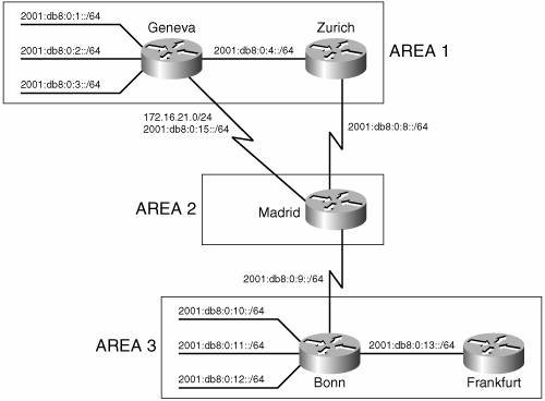 Example 10-40. Geneva's IPv6 IS-IS configuration.Hostname Geneva ipv6 unicast-routing ! interface FastEthernet0/0 ip address 172.16.4.1 255.255.255.0 ip router isis isis password magic ipv6 address 2001:db8:0:4::1/64 ipv6 router isis ! interface s 0/0.1 point-to-point ip address 172.16.21.1 255.255.255.0 ip router isis ipv6 address 2001:db8:0:15::1/64 ipv6 router isis ! interface FastEthernet0/1 ip address 172.16.1.1 255.255.255.0 ipv6 address 2001:db8:0:1::1/64 ip router isis ipv6 router isis ! interface FastEthernet0/2 ip address 172.16.2.1 255.255.255.0 ipv6 address 2001:db8:0:2::1/64 ip router isis ipv6 router isis ! interface FastEthernet0/3 ip address 172.16.3.1 255.255.255.0 ipv6 address 2001:db8:0:3::1/64 ip router isis ipv6 router isis ! router isis net 01.0004.c150.f1c0.00 authentication mode md5 authentication key-chain forest The IS-IS routing process has not been changed. An IPv6 address has been added to each interface and IS-IS for IPv6 has been enabled on each interface. The other routers are configured similarly. The IPv6 addresses in Figure 10-54 are summarized similarly to the IPv4 addresses. Zurich, Geneva, and Bonn summarize the routes as they are advertised to the L2 routers. IPv6 addresses are summarized under the global IS-IS routing process by specifying the IPv6 address family and configuring the address range to be summarized (see Example 10-41 through Example 10-43). Example 10-41. Zurich is summarizing IPv6 routes.router isis address-family ipv6 summary-prefix 2001:db8::/62 Example 10-42. Geneva is summarizing IPv6 routes.router isis address-family ipv6 summary-prefix 2001:db8::/62 Example 10-43. Bonn is summarizing IPv6 routes.router isis address-family ipv6 summary-prefix 2001:db8:0:10::/62 Example 10-44 shows Madrid's IPv6 route table, with Zurich's, Geneva's, and Bonn's summarized address ranges. Example 10-44. Madrid's IPv6 route table shows addresses summarized by Zurich, Geneva, and Bonn.Madrid#show ipv6 route IPv6 Routing Table - 12 entries Codes: C - Connected, L - Local, S - Static, R - RIP, B BGP U - Per-user Static route I1 - ISIS L1, I2 - ISIS L2, IA - ISIS interarea, IS - ISIS summary O - OSPF intra, OI - OSPF inter, OE1 - OSPF ext 1, OE2 - OSPF ext 2 ON1 - OSPF NSSA ext 1, ON2 - OSPF NSSA ext 2 I2 2001:DB8::/62 [115/20] via FE80::204:C1FF:FE50:F1C0, Serial0/0.3 I2 2001:DB8:0:4::/64 [115/20] via FE80::2B0:64FF:FE30:1DE0, Serial0/0.1 via FE80::204:C1FF:FE50:F1C0, Serial0/0.3 C 2001:DB8:0:8::/64 [0/0] via ::, Serial0/0.1 L 2001:DB8:0:8::1/128 [0/0] via ::, Serial0/0.1 C 2001:DB8:0:9::/64 [0/0] via ::, Serial0/0.2 L 2001:DB8:0:9::1/128 [0/0] via ::, Serial0/0.2 C 2001:DB8:0:15::/64 [0/0] via ::, Serial0/0.3 L 2001:DB8:0:15::2/128 [0/0] via ::, Serial0/0.3 I2 2001:DB8:0:10::/62 [115/20] via FE80::205:5EFF:FE6B:50A0, Serial0/0.2 L FE80::/10 [0/0] via ::, Null0 L FF00::/8 [0/0] via ::, Null0 Madrid#IPv4 and IPv6 share the same topology and, therefore, the same metric values. IPv6 TLVs use extended metrics, but by default, IPv4 uses the narrow metric style with a maximum value of 63. The IPv6 metric is, therefore, also limited to 63. The default value for each interface is 10. The metric style can be changed using the metric-style command. The keywords wide, transition, or wide transition enable the router to send or accept narrow- and wide-style metrics during network reconfiguration. The type of metric used can be seen in the output of the command show clns protocol, displayed in Example 10-45. Example 10-45. Zurich is configured to use the default narrow metric style.Zurich#show clns protocol IS-IS Router: <Null Tag> System Id: 0000.0C76.5B7C.00 IS-Type: level-1-2 Manual area address(es): 01 Routing for area address(es): 01 Interfaces supported by IS-IS: Serial0/0.1 - IP - IPv6 Ethernet0/0 - IP - IPv6 Redistribute: static (on by default) Distance for L2 CLNS routes: 110 RRR level: none Generate narrow metrics: level-1-2 Accept narrow metrics: level-1-2 Generate wide metrics: none Accept wide metrics: none Zurich#As seen in Example 10-45, Zurich sends and accepts narrow metrics only. Notice that the metric style is not specific for either IPv4 or IPv6. Zurich's metric-style configuration is changed as in Example 10-46. Example 10-46. Zurich is configured with the metric style in transition mode, accepting and sending both wide and narrow metrics.router isis metric-style transition address-family ipv6 summary-prefix 2001:db8::/62 The keyword transition causes the router to send and accept wide metrics and narrow metrics. Example 10-47 shows the results on Zurich. Example 10-47. Both narrow and wide metrics are generated and accepted.Zurich#show clns protocol IS-IS Router: <Null Tag> System Id: 0000.0C76.5B7C.00 IS-Type: level-1-2 Manual area address(es): 01 Routing for area address(es): 01 Interfaces supported by IS-IS: Serial0/0.1 - IP - IPv6 Ethernet0/0 - IP - IPv6 Redistribute: static (on by default) Distance for L2 CLNS routes: 110 RRR level: none Generate narrow metrics: level-1-2 Accept narrow metrics: level-1-2 Generate wide metrics: level-1-2 Accept wide metrics: level-1-2 Zurich# Case Study: Transition to Multiple Topology ModeA problem has arisen in the network shown in Figure 10-54. Frankfurt's IOS does not support IPv6. When IPv6 is configured on Bonn and the rest of the network, by default, IPv6 is added to the single IS-IS topology that is created for each level for IPv4. Because a single topology exists for each level, and the topology is shared by both IPv4 and IPv6, IPv4 and IPv6 must both be configured on each link and each router. If a single topology is used, and both IPv4 and IPv6 are configured, every link that has an IPv4 address must also have an IPv6 address. The problem can be seen on Bonn. When IPv6 was configured, the IS-IS adjacency with Frankfurt failed. debug isis adj-packets, shown in Example 10-48, shows the problem with the IPv6 address. Example 10-48. debug isis adj-packets shows an error with the IPv6 addressing in single topology mode.Bonn#debug is adj-packets fastethernet0/0 IS-IS Adjacency related packets debugging is on Bonn# ISIS-Adj: Sending L1 LAN IIH on FastEthernet0/0, length 1497 ISIS-Adj: Sending L2 LAN IIH on FastEthernet0/0, length 1497 ISIS-Adj: Rec L1 IIH from 0000.0c8d.34f1 (FastEthernet0/0), cir type L1, cir id 0000.0C0A.2AA9.01, length 1497 ISIS-Adj: No usable IPv6 linklocal addresses in LAN IIH from FastEthernet0/0 IOS supports multiple topology IS-IS in addition to the default single topology mode.[26] In single topology mode, IPv4, IPv6, and CLNS share the same IS-IS topology. When multi-topology is configured, IOS supports two topologies: one for IPv6, the other for IPv4 and CLNS. Individual SPF are computed for each topology.
As explained earlier in the section "Multiple Topologies," single topology IS-IS and multiple topology IS-IS use different TLVs to exchange information. A router that does not support multi-topology will not interpret multi-topology TLVs. A multi-topology router will process single-topology TLVs: If no multi-topology TLVs are received over an adjacency, the receiving router assumes the neighbor to be part of the IPv4/CLNS topology. This could be problematic when single topology mode and IPv6 are already configured in the network and you want to migrate to multiple topologies. During the migration, areas of the IPv6 network could become unreachable. IOS provides a transition mode, in which both single topology and multi-topology TLVs are sent, but the routers operate only in single topology mode. After all routers are configured, transition mode can be removed. The use of extended metrics, which are used in multi-topology TLVs, must be configured on the router before multi-topology can be configured. Multi-topology is configured in the network shown in Figure 10-54. All routers are first configured in transition mode, with the configuration in Example 10-49. Example 10-49. All routers in Figure 10-54 have this configuration.router isis metric-style wide transition address-family ipv6 multi-topology transition Frankfurt does not support IPv6 or multi-topology mode. The only configuration change on Frankfurt is to change to the wide metric-style. Since no multi-topology TLVs are sent from Frankfurt, the Frankfurt router and its links remain part of the default IPv4 topology. Two commands are needed to change from single topology mode to multi-topology mode: The first command changes the metric style from narrow to wide, and the second command enables multi-topology mode. The new topology shares the NET and the L1/L2 boundaries with the IPv4 topology. The two different topologies can be seen on Bonn. Bonn's IS-IS IPv6 topology shows IPv6 paths to L1 routers and L2 routers. There are two entries for L1 routers. One is for Bonn itself. The other is for Frankfurt. The asterisks mean that there is no IPv6 path to this router, but a link does exist. Compare the IPv6 topology with the IPv4 topology. Example 10-50 shows the output of show isis ipv6 topology and show isis topology. The command show isis topology displays the default, IPv4 topology. Example 10-50. The IPv4 topology and the IPv6 topology are displayed on the Bonn router.Bonn#show isis ipv6 topology IS-IS IPv6 paths to level-1 routers System Id Metric Next-Hop Interface SNPA Bonn -- Frankfurt ** IS-IS IPv6 paths to level-2 routers System Id Metric Next-Hop Interface SNPA Bonn -- Zurich 20 Madrid Se0/0.1 DLCI 171 Madrid 10 Madrid Se0/0.1 DLCI 171 Geneva 20 Madrid Se0/0.1 DLCI 171 Bonn#show isis topology IS-IS paths to level-1 routers System Id Metric Next-Hop Interface SNPA Bonn -- Frankfurt 10 Frankfurt Fa0/0 0000.0c8d.34f1 IS-IS paths to level-2 routers System Id Metric Next-Hop Interface SNPA Bonn -- Zurich 20 Madrid Se0/0.1 DLCI 171 Madrid 10 Madrid Se0/0.1 DLCI 171 Geneva 20 Madrid Se0/0.1 DLCI 171 Bonn# A single adjacency is formed over point-to-point links if at least one topology exists. The show clns is-neighbors detail command in Example 10-51 shows that Bonn has one adjacency on Serial0/0.1 to Madrid, but that two topologies share that adjacency, IPv4 and IPv6. Example 10-51. A single adjacency is formed between Bonn and Madrid, shared by both the IPv4 and the IPv6 topologies.Bonn#show clns is-neighbors detail System Id Interface State Type Priority Circuit Id Format Madrid Se0/0.1 Up L2 0 00 Phase V Area Address(es): 03 IP Address(es): 172.16.9.1* IPv6 Address(es): FE80::204:C1FF:FE50:E700 Uptime: 00:23:14 NSF capable Topology: IPv4, IPv6 Frankfurt Fa0/0 Up L1 64 Bonn.01 Phase V Area Address(es): 03 IP Address(es): 172.16.19.2* Uptime: 00:23:17 Bonn#Case Study: Route Leaking Between LevelsRecall that when an L1/L2 router sends its L1 LSP into an area, it signals other L1 routers that it can reach another area by setting the Attached (ATT) bit in the LSP. The L1 routers forward packets to the nearest L2 router (measured as the least cost path to a router with the ATT bit set) when forwarding packets out of the area. Consider the network in Figure 10-55. In area 1, both Prague and Bucharest are L1/L2 routers. They both set the ATT bit on L1 updates sent to Belgrade and Zagreb, both L1 routers. Example 10-52 is a display of Belgrade's IS database. Figure 10-55. A network with multiple L1/L2 routers in area 1 could result in inefficient routing from area 1 to other areas.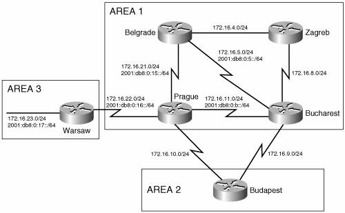 Example 10-52. The IS-IS database of an L1 router in area 1 shows two L1/L2 routers with the ATT bit set.Belgrade#show is database IS-IS Level-1 Link State Database: LSPID LSP Seq Num LSP Checksum LSP Holdtime ATT/P/OL Bucharest.00-00 0x00000052 0xE802 1104 1/0/0 Prague.00-00 0x00000052 0xEDC1 1099 1/0/0 Zagreb.00-00 0x0000003B 0x13A5 1076 0/0/0 Belgrade.00-00 * 0x00000050 0x5EC1 485 0/0/0 Belgrade#Belgrade's IS-IS database shows all routers in area 1. Prague and Bucharest are both L1/L2 routers and, therefore, have set the ATT bit. Recall that L1 routers use the closest L1/L2 router to forward traffic out of the area. Both L1/L2 routers are equal distance to Belgrade. Belgrade's IPv4 route table (Example 10-53) and IPv6 route table (Example 10-54) show that the both Bucharest and Prague will be used to forward traffic out of the area. Example 10-53. The IPv4 route table on the L1 router Belgrade shows two paths out of the area, indicated by two default routes.Belgrade#show ip route Codes: C - connected, S - static, R - RIP, M - mobile, B BGP D - EIGRP, EX - EIGRP external, O - OSPF, IA - OSPF inter area N1 - OSPF NSSA external type 1, N2 - OSPF NSSA external type 2 E1 - OSPF external type 1, E2 - OSPF external type 2 i - IS-IS, su - IS-IS summary, L1 - IS-IS level-1, L2 - IS-IS level-2 ia - IS-IS inter area, * - candidate default, U - per-user static route o - ODR, P - periodic downloaded static route Gateway of last resort is 172.16.5.1 to network 0.0.0.0 172.16.0.0/24 is subnetted, 8 subnets C 172.16.21.0 is directly connected, Serial0/0.1 i L1 172.16.22.0 [115/20] via 172.16.21.2, Serial0/0.1 i L1 172.16.8.0 [115/20] via 172.16.4.2, Serial0/0.2 [115/20] via 172.16.5.1, Serial0/0.3 i L1 172.16.9.0 [115/20] via 172.16.5.1, Serial0/0.3 i L1 172.16.10.0 [115/20] via 172.16.21.2, Serial0/0.1 i L1 172.16.11.0 [115/20] via 172.16.21.2, Serial0/0.1 [115/20] via 172.16.5.1, Serial0/0.3 C 172.16.4.0 is directly connected, Serial0/0.2 C 172.16.5.0 is directly connected, Serial0/0.3 i*L1 0.0.0.0/0 [115/10] via 172.16.5.1, Serial0/0.3 [115/10] via 172.16.21.2, Serial0/0.1 Belgrade# Example 10-54. The IPv6 route table on the L1 router Belgrade shows two paths out of the area, indicated by two default routes.Belgrade#show ipv6 route IPv6 Routing Table - 9 entries Codes: C - Connected, L - Local, S - Static, R - RIP, B BGP U - Per-user Static route I1 - ISIS L1, I2 - ISIS L2, IA - ISIS interarea, IS - ISIS summary O - OSPF intra, OI - OSPF inter, OE1 - OSPF ext 1, OE2 - OSPF ext 2 ON1 - OSPF NSSA ext 1, ON2 - OSPF NSSA ext 2 I1 ::/0 [115/10] via FE80::204:C1FF:FE50:E700, Serial0/0.1 via FE80::204:C1FF:FE50:F1C0, Serial0/0.3 C 2001:DB8:0:5::/64 [0/0] via ::, Serial0/0.3 L 2001:DB8:0:5::2/128 [0/0] via ::, Serial0/0.3 I1 2001:DB8:0:B::/64 [115/20] via FE80::204:C1FF:FE50:F1C0, Serial0/0.3 via FE80::204:C1FF:FE50:E700, Serial0/0.1 C 2001:DB8:0:15::/64 [0/0] via ::, Serial0/0.1 L 2001:DB8:0:15::1/128 [0/0] via ::, Serial0/0.1 I1 2001:DB8:0:16::/64 [115/20] via FE80::204:C1FF:FE50:E700, Serial0/0.1 L FE80::/10 [0/0] via ::, Null0 L FF00::/8 [0/0] via ::, Null0 Belgrade# As you can see in Example 10-53 and Example 10-54, only L1 routes are in Belgrade's route table. All addresses outside of the area follow the path indicated by the default route. The default routes (IPv4: 0.0.0.0/0, IPv6: ::/0) show two next-hop addresses, one via Bucharest (S0/0.3) and one via Prague (S0/0.1). 172.16.23.0/24 and 2001:db8:0:17::/64 are addresses connected to the Warsaw router, in area 3. The best path for Belgrade to take to these addresses is via Prague. However, because both Bucharest and Prague are equal distance L1/L2 routers, Belgrade will load share between the L1/L2 routers when sending traffic to 172.16.23.0/24 or 2001:db8:0:17::/64. Half of the traffic will take the optimal path, the other half will take a longer path. Example 10-55 shows Belgrade pinging 172.16.23.1 and recording the route. One route is via Bucharest (172.16.11.2), the other is via Prague (172.16.22.2). Example 10-55. Ping with the record route option shows the round trip path a packet takes from Belgrade to Warsaw.Belgrade#ping Protocol [ip]: Target IP address: 172.16.23.1 Extended commands [n]: y Loose, Strict, Record, Timestamp, Verbose[none]: r Loose, Strict, Record, Timestamp, Verbose[RV]: Type escape sequence to abort. Sending 5, 100-byte ICMP Echos to 172.16.23.1, timeout is 2 seconds: <...>Reply to request 0 (416 ms). Received packet has options Total option bytes= 40, padded length=40 Record route: (172.16.5.2) (172.16.11.2) (172.16.22.2) (172.16.23.1) (172.16.22.1) (172.16.21.2) (172.16.5.2) <*> (0.0.0.0) (0.0.0.0) End of list Reply to request 1 (216 ms). Received packet has options Total option bytes= 40, padded length=40 Record route: (172.16.21.1) (172.16.22.2) (172.16.23.1) (172.16.22.1) (172.16.21.2) (172.16.21.1) <*> (0.0.0.0) (0.0.0.0) (0.0.0.0) End of list The path that the traffic takes from Belgrade to 172.16.23.0 can be controlled by advertising the address to the L1 routers in area 1. This advertising of L2 routes to L1 router is called route leaking. The downside of route leaking is that the L1 router needs to keep track of additional addresses and paths to those addresses. Route leaking is configured by creating a list containing the addresses to be advertised into the area, and then configuring the distribution of this list to the L1 routers. Prague's configuration is displayed in Example 10-56. Example 10-56. Prague is configured to leak routes L2 routes into the L1 area.access-list 100 permit ip 172.16.23.0 0.0.0.255 any ipv6 prefix-list warsaw seq 5 permit 2001:DB8:0:17::/64 router isis redistribute isis ip level-2 into level-1 distribute-list 100 address-family ipv6 redistribute isis level-2 into level-1 distribute-list warsaw exit-address-family The access list number 100 defines the IPv4 addresses to be advertised and the prefix-list named warsaw defines the IPv6 addresses to be advertised. The redistribute isis ip command looks for L2 IPv4 addresses that match the list 100 and advertises them to L1 routers within the area. The redistribute isis command listed under the address-family ipv6 command looks for L2 IPv6 addresses that match those defined in the prefix-list named warsaw, and advertises them to the L1 area. Access-lists are discussed in Appendix B, and route redistribution is discussed in more detail in Chapter 11. Leaked routes are advertised the same way as other addresses: in type 128, 130, or 135 IPv4 Reachability TLVs, and type 236 and 237 IPv6 Reachability TLVs. TLV 128 and 130 are used with narrow-type metrics, and 135 is used with wide metrics. To distinguish leaked routes from other connected IP routes or external IP routes an Up/Down bit is defined, as discussed previously in the section "Domain-Wide Prefix Distribution." If the Up/Down bit is set to 0, the route originated in this L1 area. If the Up/Down bit is set to 1, the route was leaked from L2. Setting this bit helps keeps route loops from occurring. A L1/L2 router will not advertise an L1 address that has the Up/Down bit set to another L2 router. A route that was leaked into L1 is identifiable in the route table and in the IS-IS database. Example 10-57 and Example 10-58 display Belgrade's IPv4 and IPv6 route tables, respectively, and Example 10-59 displays Belgrade's IS-IS database. Example 10-57. The leaked address in the route table is identified as an "ia" route, or inter-area route.Belgrade#show ip route Codes: C - connected, S - static, R - RIP, M - mobile, B BGP D - EIGRP, EX - EIGRP external, O - OSPF, IA - OSPF inter area N1 - OSPF NSSA external type 1, N2 - OSPF NSSA external type 2 E1 - OSPF external type 1, E2 - OSPF external type 2 i - IS-IS, su - IS-IS summary, L1 - IS-IS level-1, L2 - IS-IS level-2 ia - IS-IS inter area, * - candidate default, U - per-user static route o - ODR, P - periodic downloaded static route Gateway of last resort is 172.16.5.1 to network 0.0.0.0 172.16.0.0/24 is subnetted, 9 subnets C 172.16.21.0 is directly connected, Serial0/0.1 i L1 172.16.22.0 [115/20] via 172.16.21.2, Serial0/0.1 i ia 172.16.23.0 [115/30] via 172.16.21.2, Serial0/0.1 i L1 172.16.8.0 [115/20] via 172.16.4.2, Serial0/0.2 [115/20] via 172.16.5.1, Serial0/0.3 i L1 172.16.9.0 [115/20] via 172.16.5.1, Serial0/0.3 i L1 172.16.10.0 [115/20] via 172.16.21.2, Serial0/0.1 i L1 172.16.11.0 [115/20] via 172.16.21.2, Serial0/0.1 [115/20] via 172.16.5.1, Serial0/0.3 C 172.16.4.0 is directly connected, Serial0/0.2 C 172.16.5.0 is directly connected, Serial0/0.3 i*L1 0.0.0.0/0 [115/10] via 172.16.5.1, Serial0/0.3 [115/10] via 172.16.21.2, Serial0/0.1 Belgrade# Example 10-58. The leaked IPv6 address in the route table is identified as "IA," inter-area.Belgrade#show ipv6 route IPv6 Routing Table - 10 entries Codes: C - Connected, L - Local, S - Static, R - RIP, B BGP U - Per-user Static route I1 - ISIS L1, I2 - ISIS L2, IA - ISIS interarea, IS - ISIS summary O - OSPF intra, OI - OSPF inter, OE1 - OSPF ext 1, OE2 - OSPF ext 2 ON1 - OSPF NSSA ext 1, ON2 - OSPF NSSA ext 2 I1 ::/0 [115/10] via FE80::204:C1FF:FE50:E700, Serial0/0.1 via FE80::204:C1FF:FE50:F1C0, Serial0/0.3 C 2001:DB8:0:5::/64 [0/0] via ::, Serial0/0.3 L 2001:DB8:0:5::2/128 [0/0] via ::, Serial0/0.3 I1 2001:DB8:0:B::/64 [115/20] via FE80::204:C1FF:FE50:F1C0, Serial0/0.3 via FE80::204:C1FF:FE50:E700, Serial0/0.1 C 2001:DB8:0:15::/64 [0/0] via ::, Serial0/0.1 L 2001:DB8:0:15::1/128 [0/0] via ::, Serial0/0.1 I1 2001:DB8:0:16::/64 [115/20] via FE80::204:C1FF:FE50:E700, Serial0/0.1 IA 2001:DB8:0:17::/64 [115/30] via FE80::204:C1FF:FE50:E700, Serial0/0.1 L FE80::/10 [0/0] via ::, Null0 L FF00::/8 [0/0] via ::, Null0 Belgrade# Example 10-59. The leaked address in the IS-IS database is identified as an IP-inter-area address.Belgrade#show is database Prague.00-00 detail l1 IS-IS Level-1 LSP Prague.00-00 LSPID LSP Seq Num LSP Checksum LSP Holdtime ATT/P/OL Prague.00-00 0x0000006D 0x7A37 655 1/0/0 Area Address: 01 Topology: IPv4 (0x0) IPv6 (0x4002 ATT) NLPID: 0xCC 0x8E Hostname: Prague IP Address: 172.16.11.1 Metric: 10 IP 172.16.22.0/24 Metric: 10 IP 172.16.21.0/24 Metric: 10 IP 172.16.10.0/24 Metric: 10 IP 172.16.11.0/24 IPv6 Address: 2001:DB8:0:15::2 Metric: 10 IPv6 (MT-IPv6) 2001:DB8:0:16::/64 Metric: 10 IPv6 (MT-IPv6) 2001:DB8:0:15::/64 Metric: 10 IPv6 (MT-IPv6) 2001:DB8:0:B::/64 Metric: 10 IS-Extended Belgrade.00 Metric: 10 IS-Extended Bucharest.00 Metric: 10 IS (MT-IPv6) Belgrade.00 Metric: 10 IS (MT-IPv6) Bucharest.00 Metric: 20 IP-Interarea 172.16.23.0/24 Metric: 20 IPv6-Interarea (MT-IPv6) 2001:DB8:0:17::/64 Belgrade# The route tables display the IPv4 and IPv6 routes as IS-IS inter-area routes, designated by the type "ia" for IPv4 and "IA" for IPv6. The database entry for the router that originated the leak shows the addresses as IP-Interarea and IPv6-Interarea. Case Study: Multiple L1 Areas Active on a RouterIOS supports the ability to have multiple, active, L1 areas on a single router: Up to 29 L1 areas can be configured, but only one L2 area. By default, the first configured IS-IS routing process defines the L2 area. It can also define a single L1 area. To enable additional L1 areas on the router, additional IS-IS routing processes are defined. Routers within each of the configured L1 areas can communicate together via this L1/L2 router. Because each area does not have to have a unique L1/L2 router to reach the rest of the network, the number of L1/L2 routers is minimized. In the network of Figure 10-55, Warsaw is in area 3. The Warsaw router is an L1/L2 router for the area. The only connection from Warsaw to the rest of the network is via Prague. Prague's configuration is modified so that Prague becomes the L2 router for both areas 1 and 3. Prague's new configuration is displayed in Example 10-60. Example 10-60. Prague is configured with multiple L1 areas.router isis net 01.0004.c150.e700.00 metric-style wide address-family ipv6 multi-topology router isis three net 03.0004.c150.e700.00 metric-style wide address-family ipv6 multi-topology interface Serial0/0.1 point-to-point description Warsaw ip address 172.16.22.2 255.255.255.0 ipv6 address 2001:db8:0:16::2/64 ip router isis three ipv6 router isis three The second IS-IS routing process is called "three." IS-IS three is assigned to the interface connecting Prague to Warsaw, interface Serial 0/0.1. IS-IS "three" is automatically configured as a L1 area, as seen by the show clns neighbor command on Prague (Example 10-61). Example 10-61. Multiple L1 areas are configured on Prague.Prague#show clns neighbor Area null: System Id Interface SNPA State Holdtime Type Protocol Budapest Se0/0.3 DLCI 115 Up 24 L2 IS-IS Belgrade Se0/0.2 DLCI 116 Up 26 L1 M-ISIS Bucharest Se0/0.4 DLCI 113 Up 22 L1L2 M-ISIS Area three: System Id Interface SNPA State Holdtime Type Protocol Warsaw Se0/0.1 DLCI 117 Up 28 L1 M-ISIS Prague#Warsaw can now be configured as a L1 router, because all its neighbors exist in area 3 (see Example 10-62). In this simple network, this step is not needed because Warsaw's only connection outside area 3 is to Prague, which only uses L1 communication with Warsaw. This step might be desired in larger networks, to ensure that Warsaw does not attempt L2 connections to other routers. Example 10-62. Warsaw is configured as an L1 router.router isis is-type level-1 Example 10-63 shows Warsaw's IS-IS database and the route table as a L1/L2 router. Example 10-64 shows the same tables with Warsaw as a L1 router. Example 10-63. Warsaw's database includes entries for area 3 routers and all L2 routers.Warsaw#show is database IS-IS Level-1 Link State Database: LSPID LSP Seq Num LSP Checksum LSP Holdtime ATT/P/OL Prague.00-00 0x0000000A 0x08B1 1048 1/0/0 Warsaw.00-00 * 0x00000075 0x3D13 1085 1/0/0 IS-IS Level-2 Link State Database: LSPID LSP Seq Num LSP Checksum LSP Holdtime ATT/P/OL Bucharest.00-00 0x0000007A 0x59D0 1060 0/0/0 Prague.00-00 0x00000090 0x433A 1078 0/0/0 Warsaw.00-00 * 0x00000001 0xA828 1080 0/0/0 Budapest.00-00 0x00000073 0xFE95 344 0/0/0 Budapest.01-00 0x00000066 0xFF8B 444 0/0/0 Warsaw#show ip route Codes: C - connected, S - static, R - RIP, M - mobile, B BGP D - EIGRP, EX - EIGRP external, O - OSPF, IA - OSPF inter area N1 - OSPF NSSA external type 1, N2 - OSPF NSSA external type 2 E1 - OSPF external type 1, E2 - OSPF external type 2 i - IS-IS, su - IS-IS summary, L1 - IS-IS level-1, L2 - IS-IS level-2 ia - IS-IS inter area, * - candidate default, U - per-user static route o - ODR, P - periodic downloaded static route Gateway of last resort is not set 172.16.0.0/24 is subnetted, 10 subnets i L2 172.16.21.0 [115/20] via 172.16.22.2, Serial0/0.1 C 172.16.22.0 is directly connected, Serial0/0.1 C 172.16.23.0 is directly connected, FastEthernet0/0 i L2 172.16.12.0 [115/30] via 172.16.22.2, Serial0/0.1 i L2 172.16.8.0 [115/30] via 172.16.22.2, Serial0/0.1 i L2 172.16.9.0 [115/30] via 172.16.22.2, Serial0/0.1 i L2 172.16.10.0 [115/20] via 172.16.22.2, Serial0/0.1 i L2 172.16.11.0 [115/20] via 172.16.22.2, Serial0/0.1 i L2 172.16.4.0 [115/30] via 172.16.22.2, Serial0/0.1 i L2 172.16.5.0 [115/30] via 172.16.22.2, Serial0/0.1 Warsaw#Example 10-64. Warsaw's database includes only area 3 routers and links, and its route tables contain only a default route for addresses not in area 3.Warsaw#show is database IS-IS Level-1 Link State Database: LSPID LSP Seq Num LSP Checksum LSP Holdtime ATT/P/OL Prague.00-00 0x00000009 0x2BDF 923 1/0/0 Warsaw.00-00 * 0x00000073 0x6CF3 924 0/0/0 Warsaw#show ip route Codes: C - connected, S - static, R - RIP, M - mobile, B BGP D - EIGRP, EX - EIGRP external, O - OSPF, IA - OSPF inter area N1 - OSPF NSSA external type 1, N2 - OSPF NSSA external type 2 E1 - OSPF external type 1, E2 - OSPF external type 2 i - IS-IS, su - IS-IS summary, L1 - IS-IS level-1, L2 - IS-IS level-2 ia - IS-IS inter area, * - candidate default, U - per-user static route o - ODR, P - periodic downloaded static route Gateway of last resort is 172.16.22.2 to network 0.0.0.0 172.16.0.0/24 is subnetted, 2 subnets C 172.16.22.0 is directly connected, Serial0/0.1 C 172.16.23.0 is directly connected, FastEthernet0/0 i*L1 0.0.0.0/0 [115/10] via 172.16.22.2, Serial0/0.1 Warsaw# When Warsaw was the L1/L2 router for area 3, the IS database contained entries for each router in area 3 and entries for each L2 router and all the addresses those L2 routers could reach. The route table contained entries for every reachable address in the network. As an L1 router, Warsaw has reduced the size of its IS-IS database and its route table significantly. |
EAN: 2147483647
Pages: 233