6.3 Key Strategies for Object Identification
| Over the years, I've consulted in an extremely varied set of problem domains, from medical systems to factory automation to avionics and fire control (weapons control systems). The good part about consulting in such a broad range of fields is that it is extraordinarily interesting and one gets to learn daily.[4] The bad part about that is that one is expected to sound intelligent about the problem almost immediately.[5] For any consultant to be successful in that kind of environment, he or she must have some effective strategies for working with engineers and managers who understand their problem domain very well but who are often neophytes when it comes to the application of the UML to their problems. Table 6-1 outlines what I have found to be the most effective of these object-identification strategies.
This chapter discusses all these strategies, but note that the analyst need not use them all on any specific project. These approaches are not orthogonal and the objects they find will overlap to a significant degree. In fact, many subsets of the strategies will find the exactly the same set of objects. Some methods will fit some analysts' approaches better than others. It is common to select three or four strategies on a given project and apply them more or less simultaneously. As with all modeling strategies, use those that work well for you and discard the ones that do not. 6.3.1 Underline the Noun StrategyThe first strategy works directly with the written problem or mission statement. Underline each noun or noun phrase in the statement and treat it as a potential object. Objects identified in this way can be put into four categories:
The point of the exercise is to find objects within the first category objects of interest or their classes. Actors have usually already been identified in the use case model, but occasionally some new ones are identified here. Uninteresting objects are objects that have no direct relevance to your system. Attributes also show up as nouns in the problem statement. Sometimes an attribute is clearly just a property of an object. When in doubt, tentatively classify the noun as an object. If subsequent analysis shows the object is insufficiently interesting, it can be included as an attribute of some other object. Let's see how this works by looking at an elevator, a real-time system familiar to everyone. We begin with a problem statement for an elevator system with the noun phrases emphasized:
Many of these are clearly redundant references to the same object (synonyms). Others are not of interest. The elevator cable, for example, is not nearly as interesting to the safety system as the cable tension sensor.[6] Likewise, the passengers (clearly actors) are not as interesting as the buttons they push and the indicators they read, which are likely to be inside the scope of the system under development. Other objects clearly need not be modeled at all.
A list can be constructed from the emphasized noun phrases of the likely candidate objects by this kind of analysis. Table 6-2 shows object quantities, where specified, with parentheses.
Some likely attributes of a couple of these objects are shown in Table 6-3.
You can see that this strategy quickly identified many objects but also identified nouns that are clearly not interesting to the analyst. 6.3.2 Identify the Causal ObjectsOnce the potential objects are identified, look for the most behaviorally active ones. These are objects that
The first two categories are commonly lumped together as causal objects. A causal object is an object that autonomously performs actions, coordinates the activities of component objects, or generates events. Many causal objects eventually become active objects and serve as the root composite object of a thread.[7] Their components execute within the context of the thread of the owner composite.
Clearly, the most behaviorally active objects are few in number:
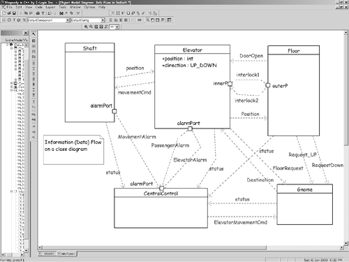
6.3.3 Identify Services (Passive Contributors)Passive objects are less obvious than causal objects. They may provide passive control, data storage, or both. A simple switch is a passive control object. It provides a service to the causal objects (it turns the light on or off on request), but does not initiate actions by itself. Passive objects are also known as servers because they provide services to client objects. Simple sensors are passive data objects. An A/D converter might acquire data on command and return it to an actor, or as the result of an event initiated by an active object. Printers and chart recorders are common passive service providers because they print text and graphics on command. A hardware passive service provider might be a chip that performs a cyclic redundancy check computation over a block of data. 6.3.4 Identify Messages and Information FlowsFor each message, there is an object that sends it, an object that receives it, and potentially, another object that processes it. Messages are the realization of information flows. Information flows, taken from older data flow diagram techniques, specify information flowing from one object to another. Information flow is usually applied in early analysis, while later analysis takes into account the packaging of these flows into messages and service calls. This strategy is very similar to the strategy of identifying service calls, but it can be applied earlier in analysis or at a higher level of abstraction. The UML 2.0 specification allows for information flows to be drawn on class diagrams; these will become associations among the classes of those objects acting as conduits for the specific messages derived from the flows. Figure 6-4 shows an example of information flows in UML 2.0. This diagram captures, at a high level of abstraction, the information flowing from one class to another. Flows are classifiers in UML and so they can be defined using standard classifier techniques statecharts, activity diagrams, operations, and attributes. These flows can be described by showing a class box stereotyped «flow» somewhere on the diagram, usually close to the flow between the objects. Notice that the flow between objects is shown as a stereotype of dependency. Figure 6-4. Information Flows
6.3.5 Identify Real-World ItemsEmbedded systems need to model the information or behavior of real-world objects even though they are not part of the system per se. For example, an anesthesia system must model the relevant properties of patients, even though customers are clearly outside the anesthesia system. Typical customer objects will contain attributes such as
An ECG monitor might model a heart as containing
In anesthesia systems, modeling organs as "sinks" for anesthetic agent uptake can aid in closed loop control of agent delivery and prevent toxemia. This strategy looks at things in the real world that interact in the system. Not all of the aspects of these real-world objects are modeled, only the ones relevant to the system. For example, the color of the heart or its neural control properties won't typically be modeled within an ECG system. Those aspects are irrelevant to the use cases realized by the ECG monitor. However, modeling its beat and PVC rate, as well as cardiac output is appropriate and relevant. If the system manipulates information about its actors, then the system should model at least their relevant aspects as objects. 6.3.6 Identify Physical DevicesReal-time systems interact with their environment using sensors and actuators in a hardware domain. The system controls and monitors these physical devices inside and outside the system and these objects are modeled as objects. Devices must also be configured, calibrated, enabled, and controlled so that they can provide services to the system. For example, deep within the inner workings of the system, processors typically perform initial power-on self-tests (POSTs) and periodic (or continuous) built-in tests (BITs). Devices frequently have nontrivial state machines and must provide status information on command. When device information and state must be maintained, the devices may be modeled as objects to hold the information about their operational status and available services. For example, a stepper motor is a physical device that can be modeled as an object with the attributes and behaviors, as shown in Table 6-4.
Normally, only the interfaces to physical devices are actually modeled within this kind of class because the object presents an interface to client objects within the system. The object itself usually focuses on the communication with the device to achieve its client's purposes and not how the device actually works. The only exception to this rule is in constructing simulation systems, in which case modeling the internal behavior of the device is the point of the object. 6.3.7 Identify Key ConceptsKey concepts are important abstractions within the domain that have interesting attributes and behaviors. These abstractions often do not have physical realizations, but must nevertheless be modeled by the system. Within the User Interface domain, a window is a key concept. In the banking domain, an account is a key concept. In an autonomous manufacturing robot, a task plan is the set of steps required to implement the desired manufacturing process. In the design of a C compiler, functions, data types, and pointers are key concepts. Each of these objects has no physical manifestation. They exist only as abstractions modeled within the appropriate domains as objects or classes. 6.3.8 Identify TransactionsTransactions are objects that must persist for a finite period of time and that represent the interactions of other objects. Some example transaction objects are outlined in Table 6-5.
In the elevator case study, an elevator request is clearly a transaction. It has a relatively short life span, either
Other examples of transactions are alarms and (reliable) bus messages. Alarms must persist as long as the dangerous condition is true or until explicitly handled, depending on the system. Alarms will typically have attributes such as
Reliable message transfer requires that a message persist at the site of the sender until an explicit acknowledgement is received. This allows the sender to retransmit if the original message is lost. Bus messages typically have attributes such as
6.3.9 Identify Persistent InformationPersistent information is typically held within passive objects such as stacks, queues, trees, and databases. Either volatile memory (RAM or SRAM) or long-term storage (FLASH, EPROM, EEPROM, or disk) may store persistent data. A robot must store and recall task plans. Subsequent analysis of the system may reveal other persistent data. For example, the information in Table 6-6 may be persistent.
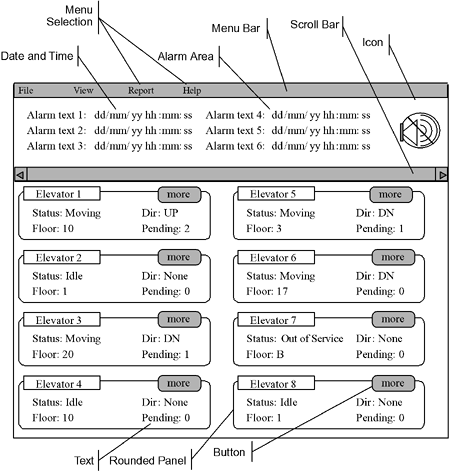
Such data can be used for scheduling equipment maintenance, and may appear in monthly or yearly reports. 6.3.10 Identify Visual ElementsMany real-time systems interact directly or indirectly with human users. Real-time system displays may be as simple as a single blinking LED to indicate power status or as elaborate as a full GUI with buttons, windows, scroll bars, icons, and text. Visual elements used to convey information to the user are objects within the user interface domain. In many environments, user interface (UI) designers specialize in the construction of visual interaction models or prototypes that the developers implement. For example, consider the sample screens for the elevator central control station shown in Figures 6-5 through 6-7. Figure 6-5. Elevator Central Station Main View
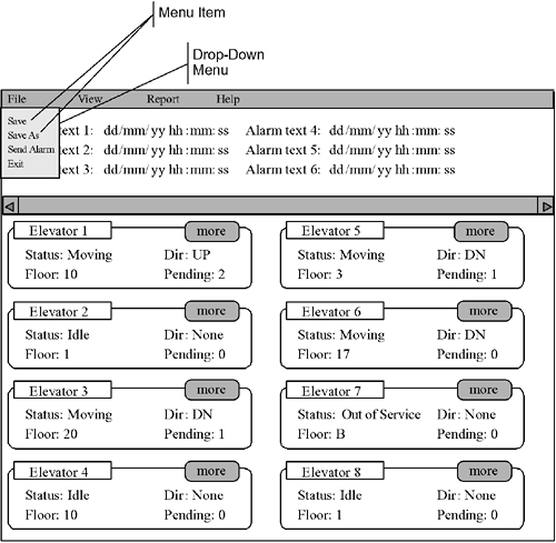
Figure 6-6. Elevator Central Station Menu View
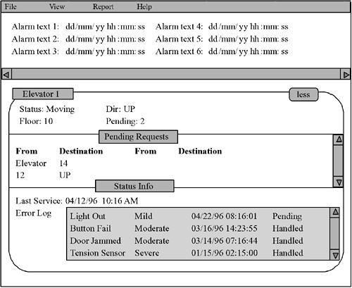
Figure 6-7. Elevator Central Station Zoom View
We see a number of common visual elements:
Each of these is an object within the UI domain for the elevator central station. These UI objects are depicted in an object message diagram later in this chapter. 6.3.11 Identify Control ElementsControl elements are entities that control other objects. These are specific types of causal objects. Some objects, called composites, often orchestrate the behaviors of their part objects. These may be simple objects or may be elaborate control systems, such as
Some control elements are physical interface devices that allow users to enter commands. The elevator case study has only a few:
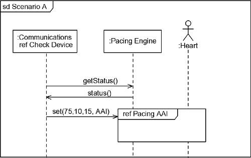
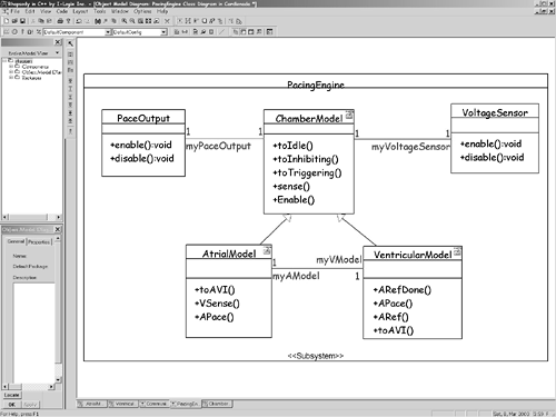
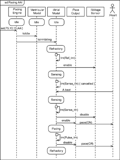
6.3.12 Apply ScenariosThe application of use case scenarios is another strategy to identify missing objects as well as to test that an object collaboration adequately realizes a use case. Using only known objects, step through the messages to implement the scenario. When "you can't get there from here," you've probably identified one or more missing objects. In mechanical terms, this is done by refining the use case scenario. Remember from Chapter 5 that the structural context for a use case scenario is the system and the actors participating in the scenario. This means that a use case scenario cannot show objects internal to the system because they are not yet known. However, once you have identified and captured the set of objects in the collaboration, you can replace the single System object with the set of objects in the collaboration. This provides a more detailed or refined view of the scenario and ensures that the collaboration does, in fact, realize the use case. For example, consider the use case scenario in Figure 6-8. It shows the black-box behavior of the pacemaker with respect to the actors Pacing Engine and Heart (and the Communications Subsystem). Using the object identification strategies previously mentioned, let's assume we can construct the model in Figure 6-9. We can now refine the scenario by elaborating the scenario with the set of identified objects, as shown in Figure 6-10. This is now a white-box view that we can relate directly to our black-box use case view. This more refined view of the same scenario, shown in Figure 6-8, shows how the objects in the collaboration work together. Note, for example, that when the Programmer instructs the pacemaker to go into AAI pacing mode, the Pacing Engine tells the Atrial Model to go to Inhibited model and the Ventricular Model to go to Idle mode. Figure 6-10 even shows the relationship between the scenario and the state models (not shown) of the Atrial Model and Ventricular Model objects. Figure 6-8. Pace the Heart in AAI Mode (Use Case Level)
Figure 6-9. Pacemaker Object Collaboration
Figure 6-10. Pace the Heart in AAI Mode (Object Level)
|
EAN: 2147483647
Pages: 127
