5.2 Use Cases
| A use case is a named capability of a structural entity in a model. Most often, use case analysis is applied only to the system as a whole, but use cases can be applied to any structural entity, including subsystems[2] or even classes. Use cases define a system-level capability without revealing or implying any particular implementation or even design of that capability. That is to say that use cases are part of the functional view of the system. As we will see shortly, use cases are implemented (realized in UML-speak) by collaborations of classes.
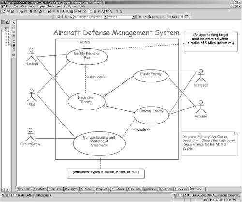
Use cases exist within a structural context. In the case of the system, this context consists of the system and associated actors. An actor is an object outside the scope of the system under discussion, which nevertheless interacts with it. In order to be a use case, the capability must return a result visible to one or more actors. If a capability of a system is invisible from the outside, then it is not a use case and should not be captured during requirements analysis (since it is a design concern). Figure 5-2 shows a simple use case diagram. Figure 5-2. Use Case Diagram
The ovals in Figure 5-2 are the use cases and the stick figures are the actors. The lines connecting the use cases with the actors are associations, meaning that the actor interacts with the system as it executes the use case; that is, messages are either sent to the actor or received from the actor while the use case is executed. The large square is called the system boundary and is optional. The diagram also shows dependency relations between the use cases, generalization of use cases, constraints (the statements inside curly braces), and comments. Used primarily in early analysis, the use case diagram shows the black-box functional capabilities provided by the system. These capabilities manifest themselves as interactions among the system and the external objects. One of the advantages of use case diagrams is their ability to capture a broad view of the primary functionality of the system in a manner easily grasped by nontechnical users. The use case diagrams can become a centralized roadmap of the system usage scenarios for people specifying the requirements of the system. It is important to note that use cases are not themselves requirements. Rather, they organize requirements into chunks, based on the organizational principle of common operational capability. This principle can be used regardless of the more detailed representation of the requirements themselves, whether it is text, sequence diagrams, state machines, or activity diagrams. It is common for a use case to represent and organize many pages of textual requirements or dozens of usage scenarios. 5.2.1 ActorsAs mentioned earlier, an actor is an object outside that scope of the system under consideration that has significant interactions with it. The icon for an actor, as shown in Figure 5-2, is a stick figure. Many people misconstrue this to mean that actors must therefore be human users of the system. An actor is any object that interacts directly with the system in ways that important to be modeled this means that they either provide information (or control inputs) to the system or receive information (or control outputs) from the system. Some writers have mistakenly stated that all use cases must be initiated from an actor or that each use case should have a single primary actor. As a matter of fact, use cases can initiate themselves (usually based on the passage of time) and often interact with many actors. Actors should be named with singular nouns[3] and represent objects outside the scope of the system under consideration that have important interactions with the system. If the use cases are being applied to a piece of a large system, such as a component or subsystem, then some of the actors will be outside the overall system while other, "internal," actors will be peer architectural pieces of the system such as other components or subsystems. From the perspective of the unit of concern, these peer architectural units are actors even though they are parts of the entire system being constructed.
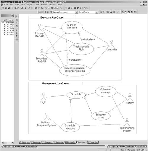
Figure 5-3 shows some of the use cases for an air traffic control system. Note that of the several actors identified, only one of them (the Controller) is a human user. All the rest are legacy systems, or devices to which the system must integrate or interface. Packages are used to group the use cases into broad categories of concern, Execution_UseCases and Management_UseCases. Packages may be used to organize systems with many use cases as appropriate. Figure 5-3. Air Traffic Control System Use Cases
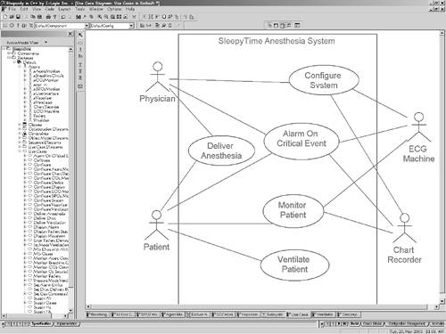
In general, not all actors participate in all use cases. The two radar actors in Figure 5-3, for example, interact with the Locate Tracks use case, but not with the other use cases. The use cases with which the actor interacts are indicated by the association drawn between the actor and the related use case. Of course, an actor can participate in more than a single use case, just as a use case may interact with multiple actors. Associations among actors are not drawn (since they are outside the scope of the system of concern), but sometimes actor generalization is shown. For example, a user in a library may participate in a Check Out Book use case, but only a certain type of user, called Librarian, may add new books to the library system or register a new user. Generalization is therefore sometimes shown among the actors. At the system level, the actors for use cases are objects outside the entire system. However, if the use case is applied to an internal subsystem or class, then the actors will be truly external actors (as in the system case) plus the peer-level subsystems or classes with which that the element under analysis associates. Consider the use cases in Figure 5-4. Here, the anesthesia system interfaces with an external ECG monitor and chart recorder. The other two actors are human users of the system the physician and the patient. Figure 5-4. Anesthesia Machine Use Cases
Now, consider a breakdown of the anesthesia machine into some large-scale subsystems, as shown in the class diagram in Figure 5-5.[4] This diagram shows the anesthesia system as a structured class containing the various subsystems as parts. Note that the subsystem stereotype is shown using two notations the iconic form for a subsystem (using a custom icon inside the object rectangle) and text. Usually only one form will be shown, but the diagram illustrates how both look.
Figure 5-5. Anesthesia Subsystems
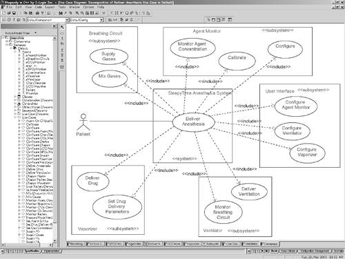
Figure 5-4 shows the use cases for the entire system. Use case analysis may be applied recursively to these subsystems as well that is, it is useful to define a set of use cases for each of the subsystems so that the subsystem teams clearly understand the responsibilities and requirements for their subsystem. In principle, these subsystem use cases should be derived from two distinct sources. First of all, the subsystem requirements must be derived from system-level requirements; they are, in essence, a project of the portion of the system requirements that the subsystem fulfills. The second source is the subsystem architecture. Even though architecture is really part of design, it groups the functionality into these large architectural units called subsystems. The subsystem requirements must take into account both the system level requirements and the architecture decomposition of the system. The question is, how do I formally (or informally) derive my subsystem-level use cases from the system-level use cases? Technically, the ROPES process does this via the «include» stereotype of dependency. This means that one use case includes or contains the smaller "part" use case, but for some reason the part use case has been extracted out and given a name. Typically, this extraction of an included use case might be done because the same "part" use case is used in more than one larger use case and extraction allows the use case to be referenced in multiple places rather than replicated. However, in this usage, the «include» relation is used to decompose a system-level use case into part use cases that will be realized by different subsystems. The extracted use cases are then realized by a single subsystem each. A system-level use case can then be decomposed into a set of subsystem-level use cases, each of which is realized by a single subsystem. Each subsystem then has a set of use cases, derived from the set of system-level use cases that define the requirements for that particular subsystem. The subsystem design and development team then has a coherent set of requirements for their subsystem. Figure 5-6 takes one of the system-level use cases, Deliver Anesthesia and performs this decomposition. This system-level use case is decomposed into 12 included use cases, each of which is realized by one subsystem. The Agent Monitor subsystem, for example, will realize the requirements specified in the derived use cases: Monitor Agent Concentration, Calibrate, and Configure. Similarly, most of the remaining subsystems must realize some other requirements for the system to meet the Deliver Anesthesia use case, including the User Interface, Ventilator, Vaporizer, and Breathing Circuit subsystems. For simplicity, the subsystem-level use cases in Figure 5-6 don't show their associated actors. Instead the actors appear on the more detailed, subsystem diagrams , Figures 5-8 through 5-14. Figure 5-6. Decomposition of Deliver Anesthesia Use Case
An assistive approach to constructing the decomposition is to decompose a system-level use case into a partially ordered sequence of activities on an activity diagram, mapping the activities to the subsystems with swim lanes. Figure 5-7 does this for the Deliver Anesthesia use case. Note the forks and joins among some of the activities this indicates that we really don't care which of these is performed first (the fork), only that they are all completed before the next step (the join). These subsystem-level activities can be represented or mapped onto subsystem-level use cases. Figure 5-7. Use Case Activity Breakdown
Note that the actors for the subsystem use cases may be actors that exist outside the entire system; they may also be other peer architectural subsystems. For convenience, we stereotype these actors with «internal» to indicate that they are inside the scope of the entire system but outside the current scope of concern. In addition, I have prefaced the name of the subsystem with an "a" to indicate that this in an internal piece of the system in an actor role in this context, such as aVentilator and aUserInterface. This is shown in the next several figures. Figure 5-8 is a use case diagram for the Ventilator subsystem. The primary use cases are to deliver ventilation (of which there are three specialized forms for different modes or kinds of ventilation) and to monitor the output of the breathing circuit. Of course, we still need to detail all the dozens or hundreds of requirements of those use cases, but that will be discussed later in this chapter. Figure 5-8. Ventilator Use Cases
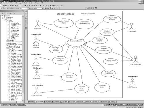
The user interface subsystem use cases are defined in Figure 5-9. Because the user interface is the means by which the physician controls and monitors the execution of the system, there are many smaller use cases (mostly specialized use cases of the Configure Device use case). Figure 5-9. User Interface Use Cases
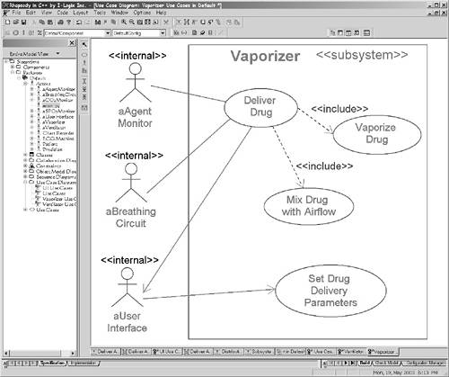
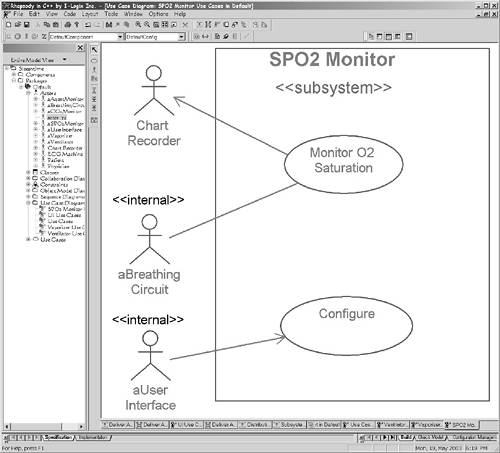
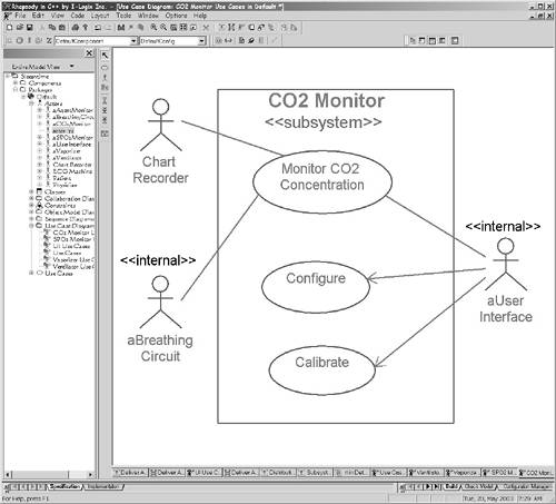
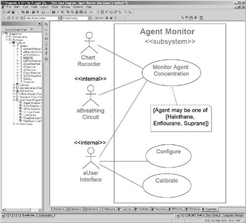
The Vaporizer subsystem's use cases are shown in Figure 5-10. We see that the Deliver Drug use case is decomposed into Vaporize Drug and Mix Drug with Airflow use cases. The SPO2 Monitor and CO2 Monitor use cases (Figures 5-11 and 5-12) look similar, but the details of how they operate and how they are set up will differ. Figure 5-13 for the Agent Monitor subsystem use cases is similar, but it also includes a constraint showing what agents may be monitored with this device. The Breathing Circuit use cases in Figure 5-14 deal with setting the gas concentration and flows, the actual delivery of the gas flows with the set concentrations and the mixing of the gases. Figure 5-10. Vaporizer Use Cases
Figure 5-11. SPO2 Monitor Use Cases
Figure 5-12. CO2 Monitor Use Cases
Figure 5-13. Agent Monitor Use Cases
Figure 5-14. Breathing Circuit Use Cases
Use cases are interactions between the system and some set of associated actors. It is important to understand what use cases are not, as it is common to waste time during use case analysis either capturing design details or functionally decomposing the internals of a system. A use case is not any of the following:
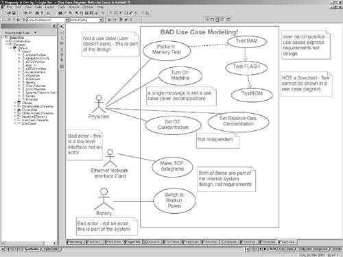
Figure 5-15 shows some of the unfortunately too-common ways to model use cases badly. A common problem is that as engineers we are primarily trained to design systems, and when first exposed to use cases, we may see them as design tools. The Make TCP Datagrams and Switch to Backup Power use cases are examples of that, but so is the use of the actors Ethernet Network Interface Card (ENIC) and Battery. The ENIC is a both a low-level interface and a design element internal to our system, and is inappropriate as an actor. What would be better? How about a use case such as Store Patient Data with an actor of Hospital Information System? The use case should be something in the user's vocabulary, not something in the engineer's design vocabulary. Similarly, the Switch to Backup Power use case is both internal and over-decomposed. A better choice would be Reliably Deliver Power, and Mains might be a reasonable actor (since it is outside the system and internally a battery can provide backup as necessary). Figure 5-15. Bad Use Case Modeling
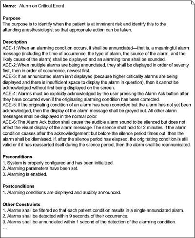
The Turn On Machine use case is probably not only a single scenario, it is probably a single message, "turn on." This is over-decomposed if this is the case. If the Turn On use case includes "perform POST" (power-on self-test), calibration, and configuration, and all of that is captured, then this would be a reasonable use case. The delivered gas mixture's relative concentrations are set via Set O2 Concentration and Set Balance Gas use cases. However, while good use cases are highly independent, these are highly interdependent. When I set the O2 concentration to 30%, I am necessarily setting the balance gas concentration to 70%. These should be collapsed into a single Set Gas Concentration use case. Perform Memory Test is a bad use case because it presumes a particular design (you can build an anesthesia machine without any computer components!) and it is outside what the user cares about. That doesn't mean that performing memory tests is bad, nor that testing shouldn't be part of the system design only that it is part of the system design and not part of the requirements. The Perform System Checkout use case is okay, though, because in typical usage the physician (or more likely, the technician) will perform periodic maintenance. The Perform Memory Test use case is then decomposed into what looks like a flow of smaller use cases Test RAM, Test FLASH, Test and ROM. Use cases do not show flow, although flow can be shown on more detailed views of requirements, including sequence diagrams, statecharts, and activity diagrams. Even if the dependency relations aren't depicting flows, they are over-decomposing the problem. Remember that a use case represents a coherent set of requirements that constitute a user-visible capability of a system without revealing or implying how that capability is achieved. Different authors will tell you different things about use cases, not all of them useful. Some authors will say that all use cases are initiated by actors. This precludes systems that have autonomous behavior a property of many real-time and embedded systems. Other authors will say that all use cases have a single primary scenario. Again, this is often but not always the case. In fact, some use cases have a number of equally important scenario variations. 5.2.2 Use Cases and TextAs developers we are all too familiar with the "Victorian novel" approach to capturing requirements the generation of hundreds or thousands of pages of text specifying requirements of complex systems. Using text alone to capture requirements is problematic because text is difficult to make simultaneously precise, unambiguous, and understandable. Besides that, textual requirements commonly lack sufficient rigor to adequately capture exactly what is meant by the requirements, allowing different interpretations to arise. Further, requirements documents are often conflicting, having requirements mismatched in different parts of large documents. Nevertheless, text is useful because it is so expressive and flexible. It is possible to employ a use case approach and specify requirements entirely in text it is simply a matter of using use cases to specify organizational units (e.g., chapters) within the Victorian novel. This approach, while having some merit, still suffers from the problems identified previously. The UML provides more formal languages (notably, statecharts, activity diagrams, and sequence diagrams) for capturing the details of requirements, as we shall see later. However, text is still useful in conjunction with these more formal approaches. It is common, for example, to provide textual information to characterize the use case. Different authors have defined different contents and formats for such textual characterizations. What I have found most useful appears in Figure 5-16. Figure 5-16. Textual Characterization of Use Cases
The figure shows several fields of information that can be entered into the use case description provided by most UML tools. The Name field is optional and need only be entered if it is otherwise impossible to disambiguate the use case in question. The Purpose field provides a location for a high-level statement as to the user purpose for the capability of the use case. The Description field is where detailed textual requirements may be stated. The Preconditions, Postconditions, and Other Constraints fields hold explicit constraints about the execution of the use case. Preconditions are conditions that must be true before the use case begins, while postconditions are conditions that are guaranteed to be true by the system after the use case is finished. The Other Constraints field is commonly used to hold (QoS requirements for the use case, such as worst-case execution time, average-case execution time, reliability, maintainability, and so on. If the description field can contain hyperlinks,[5] as they can in Rhapsody from I-Logix, then text, mathematical models, or other navigable references can be made in the UML tool. Hyperlinks are very useful in this context because clicking on them invokes the external tool to bring up the referenced document or, if an internal hyperlink, the document or referenced model elements are brought to the fore.
5.2.3 Use Case RelationsThe UML defines three distinct relationships among use cases. Generalization means that one use case is a more specialized or refined version of another. For example, the Validate User use case can be specialized into Check Password, Check Fingerprint Scan, and Check Retinal Scan use cases. Each of these subuse cases is a specialized version of the base use case. The other two kinds of use case relations are stereotypes of dependency. «include» is used when the capability described in the client use case uses the capability described in another use case. «include» should only be used when the behavior is shared among two or more use cases or is mapping the "part" use case to a system architectural component and is required for all of the client use case scenarios. The third kind of relation is «extend». «extend» is used when one use case provides an optional additional capability within a client use case. This optional capability is inserted at a named extension point. Figure 5-17 shows the syntax of the use case relations. Remember that the closed arrowhead indicates generalization with the arrow pointing to ward the more general use case. Dependency is shown with an open arrowhead and a dashed line. For an «include» relation, the arrow points to the part use case. "The Take Picture use case includes the Adjust Spacecraft Attitude use case." Perhaps confusing, but the arrowhead on the «extend» relation points in the opposite direction! "The Lossy Compression use case extends the Execute Scheduled Downlink use case." Figure 5-17. Use Case Relations
In Figure 5-17, the spacecraft turns in order to achieve two capabilities taking a picture (under the premise that you must point at something to take its picture) and executing a scheduled downlink of information. Because this common capability is required for both these use cases, it is extracted out and put into its own use case. The two means by which the spacecraft can be turned are specialized use cases of the Adjust Attitude base use case. In one case, rockets can be fired to turn the spacecraft, and in the other, reaction wheels are activated. Finally, the scheduled downlink can optionally compress images, either using lossy or non-lossy compression algorithms. Because this is an option, it is shown as an «extends» relation. Also, for risky command sequences, a high-level security clearance may be required. Note that the extension points are identified in the base use case and then referred to by the extending use cases. A caution: Too often, beginners overuse the use case relations and use them to capture the wrong things. Remember that you can model the requirements of systems without using generalization, «extends», or «includes». Their use can make a requirements model a little simpler, but not if they are misused. 5.2.4 Using Use CasesUse cases can provide a unifying strategy for the entire project development. They are an embodiment of what the customer wants and expects to see when the dust settles[6] and the product ships. Use cases group together scenarios related to the system capability described by the use and provide valuable information into all phases, as shown in Table 5-1.
5.2.5 Identifying Use CasesThere are four primary approaches to identifying use cases:
All of these approaches can work well. How does the analyst extract the primary capabilities of the system? Although some domain experts may think in abstract terms, the vast majority will be more comfortable identifying specific scenarios or specific system workflows rather than use cases. The analyst must identify the dozens (or hundreds) of scenarios that map the important system aspects and from these deduce the use cases. A number of approaches to identifying the scenarios are possible. The analyst can sit with the customer and ask probing questions, such as these:
The analyst must then identify the following for each use case:
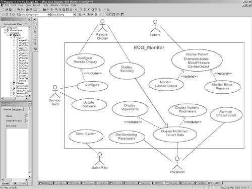
For example, the primary functions of an ECG monitor are to display waveforms for the physician, provide discrete patient numeric values (such as heart rate), and sound an alarm when the patient is at risk. Secondary functions might be to provide a remote display for the surgeon, provide a reliable software upgrade facility, allow configuration, and even support a demonstration mode of operation for the sales reps. Why is the system being built? Perhaps it provides better arrhythmia detection, color displays for better differentiation of lead configurations, or faster response times, or it interfaces to the hospital network and the operating room anesthesia machines. Figure 5-18 shows a reasonable use case model for an ECG monitor. Note that this use case diagram uses all three kinds of relations among use cases includes, extends, and generalization. Figure 5-18. ECG Use Cases
Use cases are used primarily during requirements analysis, but Figure 5-19 shows that use cases have a role in other phases of the ROPES process as well. Once the system is broken down into its primary subsystems (in the systems analysis phase), use cases may be applied to each of the subsystems in turn to define its requirements with respect to the other elements of the system. As the object model becomes fleshed out, the system- and subsystem- level use cases may be refined in more detail, replacing the system with the objects collaborating within the system to realize the specific use case. The need for additional use cases having to do with the concurrency and component models is normally uncovered during architectural design as well. Even in testing, the use cases and their associated scenarios form the key set of tests to be applied to the system. Figure 5-19. Use Cases in Development
Use cases are a powerful tool for capturing requirements and for binding those requirements into design and testing as development continues. |
EAN: 2147483647
Pages: 127