Multiple Spanning Tree
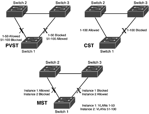
| Multiple Spanning Tree (MST) is an enhancement to IEEE's RSTP. MST is similar to Cisco's PVST. You'll recall from the last chapter that PVST has a separate instance of STP for each VLAN, and is supported on trunk connections to Cisco devices. For each STP instance, there is a separate set of BPDUs, root switches, and STP configuration information. One problem of PVST is that it adds a lot of overhead to your switching equipment. An example of PVST is shown in the top-left corner of Figure 5.3. In this example, there are 100 VLANs. Half of the VLANs (1 50) are forwarding on the left trunk from switch 1 to switch 2 and the other half (51 100) are forwarding on the right trunk from switch 1 to switch 3. With PVST, you have the ability to tune each VLAN to the network to provide an optimal loop-free topology. However, as you add more VLANs to your topology, you must tune each VLAN individually to provide an optimal STP configuration, which becomes cumbersome with a large number of VLANs. Figure 5.3. PVST, CST, and MST comparison.
CST (used with 802.1Q trunks) is shown in the top-right corner of Figure 5.3. CST's main weakness is that only one instance of STP is used. Therefore, an optimal topology can be created for only some VLANs, but not for all. In addition, you cannot use redundant connections for load balancing, like PVST. CST does have an advantage over PVST, however: It has minimal overhead. Only one set of BPDUs is used throughout the network and the amount of processing of STP information on your switches is almost negligible. The main purpose of MST is to allow multiple instances of STP, but to reduce the amount of overhead associated with Cisco's PVST. Instead of having a separate instance of STP for each VLAN, MST uses the concept of an MST instance, where multiple VLANs can be associated with an instance. An example of MST is shown in the bottom part of Figure 5.3. You associate VLANs with an MST instance. In Figure 5.3, VLANs 1 50 are associated with instance 1 and VLANs 51 100 are associated with instance 2. Each instance has its own STP components, which allows for an optimal tuning of STP. In this figure, half of the VLANs are using one link as their primary link from switch 1 while the other half are using the other link. With PVST, you would have to tune this on a per-VLAN basis. With MST, you associate VLANs to an instance and tune the instance. As you can see from this example, MST needs only two instances of STP, making it more scalable and manageable than PVST, but more optimal than CST. MST Advantages and DisadvantagesHere are the two main advantages of MST: it can implement load balancing with redundant connections, like PVST, and it has minimal overhead, like CST. Given its advantages, MST has two disadvantages. First, MST is more complex than CST, so additional training might be required of your administrators. In addition, the configuration of a mixed MST and CST network is not simple and requires some planning and additional configuration. RegionsA region in MST is where all the switches have the same base MST configuration. To belong to a region, switches must have the following information identically configured on each switch:
If two switches have this information identically configured, the two switches belong to the same region. Otherwise, the switches are considered to be in separate regions. When multicasting BPDUs, switches include the three components from the preceding list in the BPDUs. The exception to this is the VLAN table to instance mapping. This table mapping is instead run through a digest function and the output is included in the BPDU. This is to reduce the amount of information contained in the BPDU. The destination switch takes its own table and runs it through the same digest function. If the output is the same, the VLAN table mapping has been configured the same way on both switches.
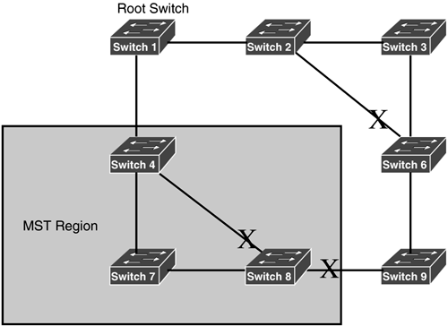
Internal Spanning TreeInternal Spanning Tree (IST) is an internal STP process that runs on an MST switch. IST is used to handle interaction between MST and CST switches. Because 802.1Q is an IEEE standard, MST must be backward-compatible with switches that support only CST. IST is used to implement this functionality and to interact with CST switches. IST essentially treats the entire MST region as a virtual switch when interacting with CST switches. An example of this is shown in Figure 5.4. Figure 5.4. IST example.
In this example, switches 4, 7, and 8 are part of an MST region. When switches 4 and 8 interact with their directly connected CST switches (1 and 9), they pretend that the switches in the MST region are actually a single virtual switch running CST. Even though all the switches in the MST region have their own unique switch IDs, they appear as a single switch ID to the CST network. However, within the MST region, each STP instance has its own spanning tree where each instance is given a number of 1 or higher. IST is always assigned a number of 0. MST does provide interoperability with Cisco's PVST+. It does this by generating BPDUs for each non-CST VLAN. MST is not fully compatible with PVST+, but does support many of its features. Table 5.4 lists the supported features.
MST Configuration and VerificationMST is disabled on your Catalyst switch by default. To enable it, use the following command: Switch(config)# spanning-tree mode mst After you've enabled MST, you must perform additional configuration tasks, including the setup of your MST instances. Here are the commands to set up your VLAN instances: Switch(config)# spanning-tree mst configuration Switch(config-mst)# name region_name Switch(config-mst)# revision revision_number Switch(config-mst)# instance instance_number vlan VLAN_range Switch(config-mst)# show current|pending Switch(config-mst)# end The name of the region and the revision number of the region must be the same on all switches if you want them to interact with each other. The instance number specifies which VLANs will belong to the specified instance. You can specify a single VLAN or a range of VLANs, such as 5-9. The show current command displays the active MST configuration after you exit your MST configuration. show pending displays the changes you've made to MST. Note that both of these show commands are done within the MST configuration section. The show spanning-tree mst configuration command displays your current MST configuration: Switch# show spanning-tree mst configuration Name [region1] Revision 1 Instance Vlans mapped -------- ---------------------------------- 0 11-4094 1 1-5 2 6-10 ---------------------------------- In this example, VLANs 1 5 have been associated with instance 1 and VLANs 6 10 have been associated with instance 2. To view general information concerning MST, use this command: Switch# show spanning-tree mst [instance_#] If you omit the instance number, it defaults to 0 (IST). Here's an example of the output of this command: Switch# show spanning-tree mst 1 ###### MST00 vlans mapped: 1-5 Bridge address 0005.7439.abcd priority 32768 (32768 sysid 0) Root address 0001.42a1.1234 priority 32768 (32768 sysid 0) port Fa0/1 path cost 200038 IST master this switch Operational hello time 2, forward delay 15, max age 20 Configured hello time 2, forward delay 15, max age 20, max hops 20 Interface Role Sts Cost Prio.Nbr Type ---------- ---- ---- ------ --------- -------- Fa0/1 Desg FWD 200000 128.1 P2p Fa0/2 Root FWD 200000 128.2 P2p Bound(PVST) Fa0/5 Desg FWD 200000 128.5 P2p There are many optional parameters for the show spanning-tree mst command. If you use the interface parameter, the command displays the switch ID, root switch, and the role, status, cost, priority, and link type of the specified interface. If you use the detail parameter, the command shows all MST information, including each interface's information. |
EAN: 2147483647
Pages: 171