Running the STP Algorithm
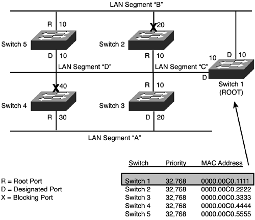
| When STP is run, one of its first jobs is to designate a root switch. After this is chosen, each switch will calculate the shortest distance (best cost) to the root. For each LAN segment, a designated switch will be chosen based on the switch that has the best cost. Ports that provide redundant connections to the root are blocked, leaving a single path to the root, thus effectively eliminating any loops. The following sections explain this process in more detail. Root Switch Election ProcessOne of the first tasks of STP is to elect the root switch. Switches sharing BPDUs will discover the current topology of the network, including all the switch identifiers. A switch's identifier consists of a 2-byte priority and a 6-byte MAC address. Based on the combination of these two pieces of information, the switch that has the lowest identifier (not necessarily the lowest MAC address) is then elected as the root. By default, all switches have the same configured priority, which means that the switch with the lowest MAC address will be chosen as the root. This can be customized, however. For optimal performance, it's recommended that you change the priority so that the switch at a central point in the broadcast domain will be chosen as the root. In a hierarchical design, this should be one of your distribution layer switches for the distribution and access layers and a core switch for the core. One issue with STP is that it guarantees a loop-free environment, but it does not guarantee an optimal configuration. For example, in Figure 4.3, Switch 1 is elected as the root switch. The root switch is necessary to build a reference point to start the calculation of the algorithm. All paths from all the switches must be able to trace a path back to the root. Figure 4.3. STP process.
Selection of Root PortsAfter the root switch is elected, each switch will determine which port, called the root port, it will use to reach the root switch. The root port is the port on a switch that has the lowest accumulated cost to the root switch. Figure 4.3 lists the root ports (R) for each bridge. If a switch receives BPDUs from multiple ports, this indicates that there are multiple paths to the root switch, and one of them will have to be chosen. If a switch has two ports to the root switch, the path that has the lower path cost is chosen. Here are the rules for choosing a root port:
After going through this selection process, the switch will have one, and only one port, that will be its root port.
Designated Switches and Designated PortsAfter the root ports for each switch are determined, designated switches and designated ports are resolved. Each LAN segment will have a designated switch, which has the lowest accumulated path cost to the root switch. All frames that are forwarded to that particular segment will go through the designated switch via its designated port, and no other ports. If two or more switches have the same path cost to the root switch for a given segment, the switch with the lower bridge identifier will be chosen as the designated switch. Through the process of elimination, eventually only one switch will remain that has a designated port for each LAN segment. In Figure 4.3, LAN segment A's designated switch is Switch 3. Note that for LAN segments B and C, the root switch is also the designated switch.
Bridging LoopsAfter the designated ports and switches have been resolved for each LAN segment, the ports on the switches connected to each segment will be placed into either a blocking or forwarding mode. The root and designated ports will be placed into forwarding mode and all other ports will be placed into a blocking mode. After the completion of this process, no loops should exist in the switched network, as shown in Figure 4.3. Note, though, that not every path from one LAN segment to another is optimal. For LAN segment A to get to LAN segment D, users must go through switches 3, 1, and then 5, which is two extra hops. Port StatesIn the previous section, two of the five port states were mentioned: blocking and forwarding. Every time a change occurs in the status of the switched network, a recomputation of the STP algorithm must take place. Interestingly, the root switch does not perform the calculation and pass its results to the rest of the switches. Each switch runs STP in parallel, builds the same spanning tree, and derives the same results for the blocking and forwarding modes for each of the switches' ports. One of the issues faced with changes is that it takes time for this convergence to take place because each port might go through four different port states: blocking, listening, learning, and forwarding, as described in Table 4.3.
Convergence IssuesBPDUs, as they are propagated through the switched network, will incur delays. Because the delays incurred to propagate the BPDUs across the bridged network might differ in length, how long it takes to incorporate the topology changes in the network could be different. To prevent this type of staggered convergence, STP uses timers. The STP algorithm is based on a diameter of seven switches or fewer, with a Hello Timer value of 2 seconds. The maximum age timer is 20 seconds (it can be between 6 40 seconds), and the Forward Delay timer is 15 seconds. Cisco recommends that you adjust these timers to reflect the diameter of your network.
Transition of Port StatesLatency is incurred when the ports have to go through their different states when a change takes place in the network. An example of a change could be a failed forwarding path, the addition of a new switch, or something as simple as the activation of a port on a switch by attaching an end station. Cisco uses a default value of 20 seconds for the Maximum Age timer (blocking) and 15 seconds for the Forward Delay timer (listening and learning), which is used to measure the time a port stays in a specific state.
During this convergence time, unfortunately, user data is not being forwarded in the network, thus causing major disruptions. You can adjust these values, where the Forward Delay value can be set as low as 4 seconds. It's recommended that if you change the timers, you should increase, not decrease, them. By decreasing them, you'll more than likely create problems. Having a lower timer means that you might not be giving your network enough time to propagate BPDUs, thus producing the likelihood of inadvertent Layer 2 loops. In times of STP instability, you should temporarily increase the Forward Delay and Maximum Age timers. |
EAN: 2147483647
Pages: 171