Advanced Topics
In Chapter 1, we described how visual modeling tools are more than simply drawing tools. As well as enabling you to draw pictures, such tools have an understanding of what those pictures actually mean. Visio for Enterprise Architects marked a transition from Visio as a drawing tool to Visio as a (UML) modeling tool, yet it fell short of the capabilities offered by contemporary UML tools by not providing support for the following:
-
Code Synchronization: The capability to see changes made in code reflected immediately on diagrams, and vice versa, with no explicit code generation or reverse engineering steps
-
.NET Framework Classes on class diagrams: The capability to visualize and explore the relationships between .NET Framework classes themselves using class diagrams
Class Designer supports both code synchronization and the capability to visualize .NET Framework classes on diagrams, so we'll discuss that support in this section.
We'll also discuss the following features that you may have encountered in other visual design tools, but for which there is not yet any explicit support in Visual Studio 2005:
-
Patterns: This is the capability to load standard patterns from a catalogue as a mechanism for standardizing designs. Some modeling tools such as IBM-Rational XDE provide this feature. Class Designer provides no explicit support but offers some possibilities.
-
Dynamic Modeling: This is the capability to express the expected dynamic (runtime) behavior of a system as well as its static structure. This is fundamental to UML design tools but is (as yet) unsupported in the Visual Studio 2005 editions (but keep an eye on the DSL Toolkit). For some dynamic modeling, you can defer to Visio, but — as with Application Designer, described in Chapter 2 — Class Designer supports a potential workaround for limited dynamic modeling.
Though these are not supported explicitly, we can offer some workarounds to tide you over.
Code synchronization
A class diagram can provide a view of your code that shows the types (classes, interfaces, and the like), the type members (fields, properties, etc.), and the relationships between the types (including inheritance and association). Though class diagrams provide views of the code, to the extent that you can have more than one diagram reflecting the same set of classes, those views are fully synchronized with the code, so any changes you make in code are reflected automatically in the diagrams, and vice versa.
If you like, you can try this out again to satisfy yourself that it works, perhaps using the file in our sample solution if you have not built your own. Make a change to the StockDeal class in the source file StockDealClasses.vb and see that change reflected automatically in the two class diagrams showing that class (Figure 5-3 and Figure 5-4). Then make a change to that class on one of the class diagrams to see the change reflected in source code and on the other diagram.
Unlike tools such as IBM Rational XDE, which require you to synchronize manually after each change, or which synchronize automatically on saving a file, Class Designer synchronizes immediately when a change is made. However, note the following proviso: References to types in other projects cannot be displayed in class diagrams until you build the referenced project, and changes to the code of external entities are not reflected until the project is rebuilt. Class Designer does not have the concept of deferred implementation that Application Designer has (see Chapter 2). Each and every change to the model is immediately reflected in code, and each change to the code is immediately reflected in the model. In this way, it can be said that "the code is the model, and the model is the code."
.NET Framework classes on Class Diagrams
We've suggested that one of the key capabilities provided by any credible visual design tool should be the representation of language and framework classes themselves. For example, Rational Rose provides UML representations of the J2SE (Java 2 Standard Edition) and J2EE (Java 2 Enterprise Editions) class libraries, and Rational XDE provides UML representations of the .NET Framework classes, but Visio for Enterprise Architects provides only language types with no representations of .NET Framework classes themselves.
| Note | It is possible to import representations of the .NET Framework classes into Visio for Enterprise Architects using the RE.NET reverse engineering utility described at http://www.lotontech.com/visualmodeling/RENET.html. |
Visual Studio 2005 Class Designer enables the classes from the .NET Framework assemblies or any third-party assemblies to be represented on class diagrams. This can be achieved in various ways.
One way is to right-click a class that inherits from a .NET Framework class or from any other class in a referenced assembly, and then choose Show Base Type from the pop-up menu. The base class will appear on your diagram with an inheritance connector between it and the derived class.
Another way is to right-click a field whose type is that of a .NET Framework class or a third-party referenced class, and then choose Show As Association from the pop-up menu. The type of that field will be shown explicitly on the design surface as a separate class, with an association line between it and the containing class.
| Note | Remember that showing members as fields or associations in Visual Studio 2005 Class Diagrams is fully reversible because the representation in code is the same either way. This is in contrast to tools such as Rational Rose that establish members as attributes (like fields) or associations according to the reverse-engineering settings, by allowing you to designate certain object classes (such as String) as basic types for which associations should not be established. |
A third way of showing .NET Framework classes and other referenced classes on a class diagram is simply to drag those classes from the Class View or the Object Browser onto the design surface. This is the most flexible technique because the classes you choose need not be referenced by existing classes in your design, but their containing assemblies must be referenced by your project.
We've used the word "class" throughout the foregoing discussion for consistency, but rest assured that you can represent other .NET Framework types on class diagrams just as easily — whether they are interfaces, enums, or delegates.
Patterns
In our introduction to this section, we suggested that patterns support is a desirable feature in a visual design tool, but not supported explicitly as a visual modeling capability of Class Designer. Unlike some earlier visual design tools, Class Designer is fully integrated with the Visual Studio 2005 IDE, and the IDE itself has some patternlike features, including the following:
-
The template wizards accessible via the Add New Item dialog, which allows items conforming to a standardized structure — or pattern — to be added to your project or solution. These templates may be the default ones, or supplied by third parties, or even devised by you.
-
Access to .NET Framework classes and other classes from referenced assemblies to be used as base classes in your design
-
The refactoring mechanisms for retrofitting patterns into your code. Refactoring is discussed in Chapter 11.
-
The insertion of code snippets that standardize the implementation of certain operations in code. Code snippets are discussed in Chapter 11.
In other words, Visual Studio 2005 does provide some pattern or patternlike facilities, but they are not directly accessible from Class Designer.
Template wizards cannot currently be initiated from Class Designer, though this capability might be provided in future releases as a mechanism for incorporating patterns into class diagrams. Another possibility is that future releases will allow combinations of classes (representing patterns) to be added to the toolbox as prototypes, to mirror the same functionality provided by Application Designer and Logical Datacenter Designer.
As described earlier, any combination of .NET Framework classes or other classes from referenced assemblies may be shown on the design surface. Therefore, where these represent base classes or interfaces defined by patterns — such as an AbstractFactory class or a State interface — then effectively you can present those patterns in a class diagram.
Certain refactoring types may be applied directly from Class Designer — for example, Implement Abstract Class or Extract Interface. In this respect, Class Designer does indeed support some patternlike features directly.
Because code snippets are inserted within methods, it makes little sense to drive this functionality from a Class Designer that represents method signatures without internal implementations. As an important technique in its own right, the code snippets mechanism is discussed in Chapter 11.
Having surveyed the limited degree of support for patterns provided by Class Designer, we'll now provide some practical examples that show how you could create your own pattern library, at least as a short-term measure until Visual Studio incorporates explicit patterns support.
Building your own pattern library
In this section, we'll show you how to construct a project containing C# implementations of common patterns, with supporting class diagrams. To save on the effort of implementing each pattern yourself, you can find a ready supply of pattern implementations on the web.
For demonstration purposes we took some sample pattern implementations from the Data and Object Factory "Software Design Patterns" at http://www.dofactory.com/patterns/Patterns.aspx. We chose that site mainly because the sample implementations may be used freely as long as the original copyright notices are displayed as shown in the code that follows:
// Proxy pattern -- Structure example //-------------------------------------------------------- // Copyright (C) 2001 - 2002, Data & Object Factory // All rights reserved. www.dofactory.com // // You are free to use this source code in your // applications as long as the original copyright // notice is included. // // THIS CODE AND INFORMATION IS PROVIDED "AS IS" WITHOUT // WARRANTY OF ANY KIND, EITHER EXPRESSED OR IMPLIED, // INCLUDING BUT NOT LIMITED TO THE IMPLIED WARRANTIES OF // MERCHANTABILITY OR FITNESS FOR A PARTICULAR PURPOSE. //-------------------------------------------------------- using System; // "Subject" abstract class Subject { // Methods abstract public void Request(); } // "RealSubject" class RealSubject : Subject { // Methods override public void Request() { Console.WriteLine("Called RealSubject.Request()"); } } // "Proxy" class Proxy : Subject { // Fields RealSubject realSubject; // Methods override public void Request() { // Uses "lazy initialization" if( realSubject == null ) realSubject = new RealSubject(); realSubject.Request(); } } As you may have deduced already, this C# code implements the Gang of Four (GoF) proxy pattern.
If you're familiar with UML, then you'll be used to seeing that pattern in the form of a Class Diagram. If you're not familiar with UML, and you've never met that pattern before, then it might take you a while to figure out the relationships between the three classes. Figure 5-9 shows how much clearer those relationships become when shown as a class diagram.
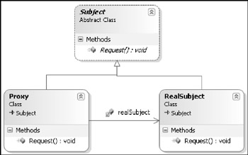
Figure 5-9
That diagram was drawn simply by dragging the source file Proxy_Structure.cs onto the diagram. Because that source file contains three class definitions, all three classes appear on the diagram.
| Important | Dragging a source file onto the design surface causes all of the classes within that source file to be shown on the diagram, so defining several interconnected classes within a single source file is a convenient way to encode a pattern. |
The inheritance relationships from the Subject class to the Proxy and RealSubject classes appeared automatically, whereas the association relationship between the Proxy and the RealSubject did not. By default, the Proxy included a field of type RealSubject, which was rendered as an association when we right-clicked the field and chose Show as Association.
| Note | Remember that Show as Field and Show as Association are completely interchangeable and do not affect the code at all. They are merely alternate display notations. |
The proxy pattern is important because it underpins many distributed computing technologies, such as Web services and .NET Remoting, not to mention CORBA and Enterprise Java Beans. A remote object (the RealSubject) may need to be represented by a local client-side class (the Proxy) that appears to behave exactly the same because the RealSubject and the Proxy both implement the same interface or abstract class. The sleight of hand is that the Proxy passes on requests to the RealSubject over the network, thus hiding the tricky networking issues from the developer.
When you begin to use this pattern, you'll want to substitute the names of the participating classes with names that are meaningful in the context of the problem you're solving. For example, you might substitute the name Subject with Bank, the name RealSubject with BankImplementation, and the name Proxy with BankProxy. A convenient way to do this is by using the Rename refactoring that is covered in Chapter 11, as it will not only rename that classes themselves but also the references between the classes.
| Note | If you've used a pattern engine such as the one in IBM Rational XDE, you will recognize this as pattern expansion, with the renaming process equivalent to the binding of values to template parameters. |
Dynamic modeling
If you're familiar with UML, you know that class diagrams represent the static structure of the classes in your application. The dynamic behavior — that is, how instances of classes react and interact over time — has traditionally been modeled in UML using statechart diagrams (for how classes react) and collaboration diagrams (for how classes interact).
Because Visual Studio 2005 does not support dynamic modeling, we'll now offer some workarounds that you could use to simulate those additional diagram types.
Simulating Statechart Diagrams using the state pattern
When designing classes using UML, it is possible to create for each (stateful) class a statechart diagram that shows the following:
-
The possible states in which an instance of that class may find itself
-
The allowable transitions between states, which occur in response to events if certain conditions are met
-
The events that an instance of that class may respond to in each state
An example statechart in UML for an Account class is shown in Figure 5-10.
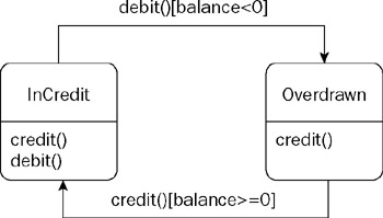
Figure 5-10
This diagram shows that an account may be in state InCredit or state Overdrawn. In state InCredit, the account can accept credits and debits (which are events), but in state Overdrawn, only credits are allowed. If the account receives a debit event while in state InCredit that causes the balance to fall below zero, then the account transitions into state Overdrawn. Conversely, if the account receives a credit event while in state Overdrawn and that credit takes the balance above zero, then the account transitions back to state InCredit.
The problem is that, currently at least, the Visual Studio 2005 editions do not provide these statecharts.
It turns out that our discussion of patterns in the previous section provides a workaround here. There is a well-known design pattern for representing an object's possible states as a set of classes. Applying the State pattern to an Account class would result in the class diagram shown in Figure 5-11.
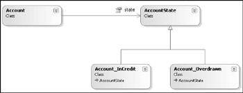
Figure 5-11
Remember that class diagrams are merely views of the underlying classes, so we can draw as many Class Diagrams as we like showing various combinations of classes. Suppose we draw a new class diagram to show only the Account_InCredit and Account_Overdrawn classes that represent states. By adding some events and associations, we can come up with the diagram shown in Figure 5-12. Are you experiencing any dj vu yet?
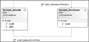
Figure 5-12
Essentially, this diagram contains all of the information contained in the earlier statechart, and it looks very similar too. Events represent events, as they should; and associations represent transitions, which is not unreasonable because you would need a navigable association between the (state) classes in order to make a transition. Because the notation is not quite powerful enough to distinguish events (debit) and conditions (balance<0), we have encoded those semantics into the association role names. That makes sense when you consider that the implementation code for that transition would be something like the following:
if (event==debit && balance<0) nextState=currentState.debit_balanceLessThanZero;
It's not ideal, but while we wait for true statecharts to be provided, this technique offers a very feasible workaround, especially if you would manage object states using the recognized State pattern anyway. We've not resorted to using comments, and where we have used specific constructs — such as Events — we've used them exactly for the purpose they are intended.
Simulating collaboration diagrams using comments
UML collaboration diagrams are essentially static structure diagrams — like class diagrams — with additional adornments showing the sequence of messages between those classes in a typical scenario. Those collaboration diagrams will often be accompanied by a participating classes diagram; a class diagram showing only those classes that participate in the collaboration.
Taking those two ideas together, in Figure 5-13 we have drawn a participating classes diagram for a "Buy Stock" scenario, and used comments to indicate a numbered sequence of messages that pass between the classes as that scenario plays out.
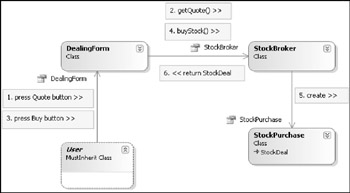
Figure 5-13
If you've read Chapter 2, you know that we first introduced this idea in the context of application diagrams, the problem there being that you can only have one application diagram per solution, so you can only show one scenario at a time. Using class diagrams, there is no such restriction because you can have as many class diagrams as you like, and therefore as many simulated collaboration diagrams as you like.
UML purists will point out that collaboration diagrams do not show interactions between classes at all; they show interactions between object instances. Well, our workaround is exactly that, a workaround, so it's not perfect; but in practice we find that the majority of collaboration diagrams are drawn as though they show classes, rather than instances. For those scenarios in which you must distinguish between two instances of the same class — for example, when transferring funds from one bank account to another — you can include an instance name with the message comments in order to set the context.
Consider the following two messages that would appear as two separate comments next to a single association line to an Account class:
1. sourceAccount.withdrawFunds() 2. destinationAccount.depositFunds()
EAN: 2147483647
Pages: 220