ATM
Asynchronous Transfer Mode (ATM) is a a cell-switched network technology used for building high-speed backbones. ATM breaks data into fixed-size cells of 53 octets. Five octets are used for the cell header; the remaining 48 are available for data. The fixed size allows an ATM switch to handle the cells quickly and efficiently. An ATM switch is allowed to drop cells as necessary if the switch's capacity is exceeded. There is a mechanism for distinguishing between cells that can be discarded and high-priority cells that should not be discarded (although even high-priority cells can be discarded if there is no alternative).[*]
[*] An exception to this rule is AAL1 (ATM Adaptation Layer 1). In the case of AAL1, no cells should be discarded. If the switch builds the AAL1 VC, it should pass all the cells. Since this is not a book about ATM, I don't have the time or space to discuss ATM adaptation layers in detail.
Sending IP packets over an ATM network presents some interesting problems. Each packet must be broken into multiple cells, since most IP packets won't fit into 48 octets. If any of the cells are dropped, the packet won't make it through the network undamaged. Therefore, the packet will probably be re-sent (it will certainly be re-sent if it's a TCP segment). In turn, this means dumping many additional cells into a switch that is already suffering from congestion. This problem is less serious if your ATM network is designed for minimal cell loss.
To run, ATM requires special (and sometimes expensive) hardware . Some of the common ATM hardware products provided by Cisco include:
- ATM Network Processor Module (4500/4700-series routers)
- ATM Interface Processor (7500-series routers)
- ATM Port Adapter (7500-series routers)
ATM-DXI allows ATM over a non-ATM interface, such as a serial interface (like HSSI). In this configuration, you typically have an ADSU (ATM CSU/DSU) connected to a high-speed serial port on your router.
6.2.1. ATM Terminology
ATM is a connection-oriented protocol. A separate connection must be established for every device with which a router wants to communicate within the ATM network. These connections are called virtual circuits (VCs). VCs can be either permanent (PVCs) or switched (SVCs) . PVCs are typically used for WAN connections; SVCs are typically used for LAN connections. The main difference between PVCs and SVCs is that SVCs can be created and destroyed automatically by the software. This dynamic creation of circuits makes administration a bit easier. On the other hand, PVCs arefor a lack of a better wordpermanent. It's hard to imagine a wide-area network in which you wouldn't want permanent circuits between your nodes. You can think of a PVC as a leased line, while an SVC is more like a dialed phone call.
A virtual circuit is defined by two numbers, assigned by your ATM provider: a Virtual Path Identifier (VPI) and a Virtual Channel Identifier (VCI) . The VPI identifies a bundle of circuits, while the VCI identifies a circuit within a bundle. It is easier to think of the VPI/VCI pair as a single parameter, like a DLCI in a Frame Relay configuration.
Before we examine our first configuration, let's look at ATM encapsulation. Several types of encapsulation are used for ATM:
aal5snap
All traffic is on one ATM circuit.
aal5mux
A dedicated circuit is set up for each protocol (IP, IPX, etc.).
aal5nlpid
Works with ATM-DXI and encapsulates over Frame Relay.
Another acronym you'll see when working with ATM is LANE, which stands for LAN Emulation. In this mode, the LANE device emulates a more traditional LAN technology, such as Ethernet. We'll discuss LANE after we learn to configure ATM.
6.2.2. Configuring Permanent Virtual Circuits
When configuring ATM for a WAN connection, you need to:
- Assign an IP address and VPI/VCI to a PVC.
- Define the encapsulation method.
- Map a remote IP address (the IP address of the router at the other end of the circuit) to the PVC.
The last step (mapping an IP address to the PVC) is required only for static mappings. Just as in Frame Relay, there are two ways to manage IP addressing: statically map the IP address of the remote router or let the router figure out the mapping itself with inverse ARP. I'll show examples of both configurations.
|

6.2.2.1. Configuring an ATM interface with static IP mapping
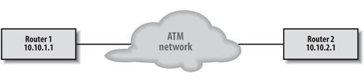
Figure 6-3 shows our ATM connection. You will see that we are again using subinterfaces to implement ATM; in more advanced settings, using subinterfaces simplifies the configuration. Here is the configuration for Router 1:
Figure 6-3. An ATM configuration
interface atm0
 no shutdown
!
interface atm0.1
 ! assign our interface's IP address
 ip address 10.10.1.1 255.255.255.0
 ! Create PVC 20 with a VPI of 0 and a VCI of 60
 atm pvc 20 0 60 aal5snap
 map-group atm-map1
!
map-list atm-map1
ip 10.10.2.1 atm-vc 20 broadcast
This configuration is simple. We have all three steps that we mentioned earlier:
- We assigned a local IP address to our ATM interface.
- We created a PVC with the atm pvc command. This command creates PVC 20, which has a VPI of 0 and a VCI of 60, and uses the aal5snap encapsulation method. The number we assign to the PVC (20) is used only for referring to the PVC in other parts of the router configuration; it has no other significance.
- We mapped a remote IP address to the PVC with the map-list command. The broadcast option within the map list is important because it allows routing-protocol updates to propagate to remote hosts. Most routing protocols rely on multicasts or broadcasts, for which ATM has no native support.
6.2.2.2. Configuring an ATM interface with dynamic IP mapping
Instead of statically mapping an IP address to the PVC, we can use inverse ARP and let the router figure out the mapping itself. Inverse ARP is not the default for ATM; we need to configure it explicitly. The following configuration is identical to the previous one, except that it uses inverse ARP instead of static mapping. As a result, the configuration is noticeably shorter, even on a simple network. For larger networks, the savings could be significant.
interface atm0
 no shutdown
interface atm0.1
 ip address 10.10.1.1 255.255.255.0 inarp 5
 atm pvc 20 0 60 aal5snap
The inarp 5 option tells the interface to use inverse ARP for mapping the IP address to the PVC and to set the time period for inverse ARP (the amount of time between inverse ARP requests) to five minutes. The default time period is 15 minutes. Now the system can respond to changes in remote addressing without a change to the ATM configuration; the router will notice any changes on the ATM network the next time it sends an ARP request. Therefore, at most five minutes will elapse before the router notices the change and adjusts its address mappings.
6.2.3. Configuring Switched Virtual Circuits
SVCs are created automatically by software. However, the software that creates and destroys SVCs requires two PVC channels for communication; these must be created explicitly, like any other PVC. One PVC channel uses VPI 0 and VCI 5 for signaling; this channel uses the encapsulation method qsaal. The other required PVC exchanges management information and uses VPI 0 and VCI 16, with ilmi encapsulation. Both of these channels are associated with the "main" ATM interface and not with any subinterfaces.
Another important piece of the SVC picture is the Network Service Access Point (NSAP) address. This address is something like a MAC address for ATM networks. That is, it's a higher-level concept than a physical address (essentially, the VPI/VCI pair) and is persistent: it doesn't change, even though the VPI/VCI to reach any destination will change as the circuit is created and destroyed. The process for creating an SVC operates like this:
- A device is ready to communicate with another device, so it sends the NSAP address of the destination device to the network signaling channels.
- The device waits for the circuit to be created.
- The device can now use the newly created circuit.
NSAP addresses are unique 20-octet hex values.
For example, consider the network in Figure 6-3. If we were to add a router named Router 3 with an IP address of 10.10.3.1, an SVC configuration for Router 1 might look like this:
interface atm1
 ! Configure the two signaling channels that are required for SVC
 atm pvc 1 0 5 qsaal
 atm pvc 2 0 16 ilmi
!
interface atm1.1
 ! Our interface's IP address
 ip address 10.10.1.1 255.255.255.0
 atm nsap-address 22.0011.01.FF1111.00FF.0000.AAAA.1111.1111.1111.11
 atm map-group atm-map
!
map-list atm-map
ip 10.10.2.1 atm-nsap 22.0011.01.AAAAAAA.00FF.0000.AAAA.1111.1111.AAAA.11
broadcast
ip 10.10.3.1 atm-nsap 22.0011.01.BBBBBBB.00FF.0000.AAAA.1111.1111.BBBB.11
broadcast
With this configuration, circuits to 10.10.2.1 and 10.10.3.1 will be created on demand. There are only a few new concepts here: the signaling channels, the nsap-address for the interface, and the static mapping of the NSAP addresses for the end routers. The configuration for the signaling channels is simple and is the same on every ATM router that uses SVCs. Similarly, the NSAP addresses are fairly easy to understand if you can deal with the long hex numbers; your biggest problem will be typing them correctly. That's a big problem, particularly in a large network: we don't want to be typing dozens of 20-byte hex numbers, which may change as the network is reconfigured. What makes the problem even worse is that this map must be replicated on all the routers in your network. The only address excluded from the map is the NSAP address of the router itself. So for a network of 10 routers, you would have to type 90 of these 20-octet NSAP addresses.
It would be great if we didn't need to configure those long NSAP addresses for every IP address on our network. But since ATM isn't a broadcast protocol, there is no way for it to learn about the possible remote NSAP addresses. However, you can do dynamic mapping if your network has an ATM ARP server. This server knows about all the NSAP addresses for your network, which means a router can query the server for NSAP addresses. This is considered Classical IP. If we had an ATM ARP server on our network, our configuration could be reduced to this:
interface atm1
 ! Configure the two signaling channels that are required for SVC
 atm pvc 1 0 5 qsaal
 atm pvc 2 0 16 ilmi
interface atm1.1
 ! Our interface's IP address
 ip address 10.10.1.1 255.255.255.0
 atm nsap-address 22.0011.01.FF1111.00FF.0000.AAAA.1111.1111.1111.11
 !
 ! Now just supply the NSAP address of the ARP server
 atm arp-server nsap 22.0011.01.AAAAAAA.00FF.0000.AAAA.1111.1111.AAAA.11
Now we have an SVC configuration with dynamic addressing.
6.2.3.1. ATM ARP server
Since having an ATM ARP server on our network greatly simplified our configuration in the previous example, I'll show you how to configure one. Only one ATM ARP server should exist for each logical IP subnet of an IP network. The configuration of an ATM interface as an ARP server is as simple as this:
interface atm0
 ip address 10.10.1.2 255.255.255.0
 atm esi-address 3031.11ba.1181.20
 atm arp-server self
We could have used the atm nsap-address command instead of the atm esi-address command. However, the End System Identifier (ESI) is preferred because it allows the ILMI address registration to work better should a router move within the ATM network.
6.2.4. Configuring with DXI
Using the ATM-DXI mode basically means that you have an ADSU connected to a high-speed serial port on your router. The ADSU in turn connects to the ATM switch and acts like a CSU/DSU. Configuration is not as complicated as having the native ATM interface: we're dealing with a familiar serial interface, and almost all of the ATM-specific complexity is handled by the ADSU. In other words, since we are using outside hardware to communicate via ATM, there is only so much we can do. Consider the following configuration:
interface serial 1
 ip address 10.10.1.1 255.255.255.0
 encapsulation atm-dxi
 ! configure for VPI of 1 and VCI of 2
 dxi pvc 1 2 mux
 ! map the IP 10.10.1.2 to VPI 1 and VCI 2
 dxi map ip 10.10.1.2 1 2 broadcast
The line dxi pvc 1 2 mux gives us a permanent virtual circuit with a VPI of 1 and a VCI of 2. It also sets the mux option, which means that only one protocol is to be used over this PVC. That protocol is defined in the next line, which maps the remote IP address 10.10.1.2 (i.e., the address of the router at the other end of this circuit) to the VPI/VCI pair. The broadcast option allows routing-protocol updates to be sent over this PVC.
6.2.5. ATM show Commands
The show commands listed in Table 6-2 are useful for configuring and troubleshooting ATM.
|
Command |
Displays |
|---|---|
|
show atm map |
All configured static ATM maps |
|
show atm vc |
Information about ATM virtual connections |
|
show atm interface |
ATM-specific information for an interface |
6.2.6. LAN Emulation (LANE)
LAN Emulation (LANE) allows an ATM network to emulate legacy LAN types, specifically Ethernet and token ring. In other words, LANE provides the advantages of ATM's larger bandwidth, which allows you to scale your network while keeping already deployed LAN applications. LANE allows you to run any broadcast LAN protocol (IP, IPX, AppleTalk, etc.) across the ATM network without the applications knowing about it. Among other things, LANE provides a way to accommodate broadcast traffic (required for LANs) over ATM, which is not a broadcast technology.
LANE works by encapsulating the LAN packets inside the ATM frames, which results in a smaller MTU because the packets are restricted by the MTU size of the emulated protocol. LANE resolves LAN MAC addresses to ATM addresses through the use of an Emulated LAN (ELAN), which is similar to a virtual LAN (VLAN). Four components are part of every LANE configuration . They are:
LAN Emulation Client (LEC)
The LEC is the ATM client that is participating in the ELAN. A device has one LEC for each ELAN in which it is participating. However, if a device participates in multiple ELANS, it can have multiple LECs (that's plural LEC, not LECS!). Devices that would use the LEC are ATM hosts, LAN switches, and routers. The LEC handles all the communications to the ELAN servers and establishes a mapping to and from LAN MAC addresses and the ATM NSAP addresses. Once the mappings are correct, the LEC opens a private virtual circuit directly to the remote device's LEC.
LAN Emulation Configuration Server (LECS)
The LECS contains the database that lists each client (LEC) and the ELAN to which the client belongs. There is one LECS per ATM network. The clients (LECs) query this server to get the NSAP address (ATM address) of the LES (the server) for their assigned ELAN.
LAN Emulation Server (LES)
The LES maps MAC addresses to NSAP addresses and maintains a database showing which clients are currently active in the ELAN. There is one LES for every ELAN.
Broadcast Unknown Server (BUS)
The BUS forwards unknown, broadcast, and multicast data to the clients in the ELANs. There is one BUS for every ELAN. Because the LES and BUS are so closely related, they are configured as one entity within the router. From this point on, we will refer to the both of them as one object called the LES/BUS.
6.2.6.1. LANE configuration notes
The following notes will help you to understand LANE configuration:
- The LECS is configured on the major ATM interface.
- The LES and LEC of the same ELAN can be configured on the same subinterface.
- Clients of different ELANs cannot be configured on the same subinterface.
- Servers of different ELANs cannot be configured on the same subinterface.
- For one client on an ELAN to talk to a client on another ELAN, a router must be present to route between the two ELANs.
- Using automatic NSAP addresses is much easier than supplying a unique NSAP address for every ELAN client. The router will automatically generate a unique NSAP address by itself with the command lane auto-config-atm-address. We use this command throughout the following examples.
6.2.6.2. Configuring the LECS
Because the LECS needs to know where the LES for each ELAN is located, and because your network may have a large number of ELANs, the LECS configuration can be quite lengthy. All of these examples include the ATM signaling configurationif ATM isn't working, you're not going to get anywhere with LANE.
In this configuration, we establish two ELANs in the LECS database. The database is called elandatabase1 and the ELANs are elan1 and elan2.
! Define the NSAP address of the LES for each and every ELAN
lane database elandatabase1
 name elan1 server-atm-address 47.00918100000000613E5D0301.00603E0DE841.01
 name elan2 server-atm-address 47.00918100000000613E5D0301.008876EF0356.08
 ! We set a default ELAN for LECs that don't know which ELAN they should
 ! join
 default-name elan1
!
! Set up the major ATM interface signaling
interface atm 0
 atm pvc 1 0 5 qsaal
 atm pvc 2 0 16 ilmi
 ! Attach the LANE database that we created to the interface
 lane config elandatabase1
 ! Tell the LECS to use automatic addressing
 lane auto-config-atm-address
6.2.6.3. Configuring the LES/BUS
We could configure the LES/BUS on the same server as the LECS. In this case, we configure it on a separate router. Once again, we are going to configure the signaling for ATM. Then we'll configure the LES/BUS with the lane server-bus command. Finally, we'll configure the interface as a client of the ELAN. If you don't make the LES/BUS a client of the ELAN, the router will function as the LES/BUS but will not be able to do any routing for the ELAN. Making it a client of the ELAN ensures that the router can be the LES/BUS for the ELAN and also route traffic for the ELAN.
! Set up the major ATM interface signaling
interface atm 0
 atm pvc 1 0 5 qsaal
 atm pvc 2 0 16 ilmi
 ! Set up LANE default addressing
 lane auth-config-atm-address
!
! Configure the LES/BUS on a separate subinterface
interface atm0.1
 ip address 10.1.1.1 255.255.255.0
 ! Configure this router as LES/BUS
 lane server-bus ethernet elan1
 ! Also make it a client of the ELAN
 lane client ethernet elan1
6.2.6.4. Configuring the LEC
The previous example used the lane client command to make the LES/BUS a client of the ELAN. This case is much simpler: we will make the router a LANE client and assume that the LES/BUS is on another device.
! Set up the major ATM interface signaling
interface atm 0
 atm pvc 1 0 5 qsaal
 atm pvc 2 0 16 ilmi
 ! Set up lane default addressing
 lane auth-config-atm-address
!
! Configure the LES/BUS on a separate subinterface
interface atm0.1
 ip address 10.2.1.1 255.255.255.0
 lane client ethernet elan2
6.2.6.5. LANE show commands
The commands in Table 6-3 are useful for configuring and troubleshooting LANE.
|
Command |
Displays |
|---|---|
|
show lane default-atm-addresses |
The automatically assigned ATM address of each LANE component |
|
show lane client |
All LANE information for each LANE client configured on an interface |
Getting Started
- Getting Started
- IOS User Modes
- Command-Line Completion
- Get to Know the Question Mark
- Command-Line Editing Keys
- Pausing Output
- show Commands
IOS Images and Configuration Files
- IOS Images and Configuration Files
- IOS Image Filenames
- The New Cisco IOS Packaging Model
- Loading Image Files Through the Network
- Using the IOS Filesystem for Images
- The Routers Configuration
- Loading Configuration Files
Basic Router Configuration
- Basic Router Configuration
- Setting the Router Name
- Setting the System Prompt
- Configuration Comments
- The Enable Password
- Mapping Hostnames to IP Addresses
- Setting the Routers Time
- Enabling SNMP
- Cisco Discovery Protocol
- System Banners
Line Commands
- Line Commands
- The line Command
- The Console Port
- Virtual Terminals (VTYs)
- Asynchronous Ports (TTYs)
- The Auxiliary (AUX) Port
- show line
- Reverse Telnet
- Common Configuration Items
Interface Commands
- Interface Commands
- Naming and Numbering Interfaces
- Basic Interface Configuration Commands
- The Loopback Interface
- The Null Interface
- Ethernet, Fast Ethernet, and Gigabit Ethernet Interfaces
- Token Ring Interfaces
- ISDN Interfaces
- Serial Interfaces
- Asynchronous Interfaces
- Interface show Commands
Networking Technologies
Access Lists
IP Routing Topics
- IP Routing Topics
- Autonomous System (AS) Numbers
- Interior and Exterior Gateway Protocols
- Distance-Vector and Link-State Routing Protocols
- Static Routes
- Split Horizon
- Passive Interfaces
- Fast Switching and Process Switching
Interior Routing Protocols
Border Gateway Protocol
- Border Gateway Protocol
- Introduction to BGP
- A Simple BGP Configuration
- Route Filtering
- An Advanced BGP Configuration
- Neighbor Authentication
- Peer Groups
- Route Reflectors
- BGP Confederacies
- BGP TTL Security
Quality of Service
- Quality of Service
- Marking
- Older Queuing Methods
- Modern IOS QoS Tools
- Congestion Avoidance
- Traffic Policing
- Traffic Shaping
- AutoQoS
- QoS Device Manager
Dial-on-Demand Routing
- Dial-on-Demand Routing
- Configuring a Simple DDR Connection
- Sample Legacy DDR Configurations
- Dialer Interfaces (Dialer Profiles)
- Multilink PPP
- Snapshot DDR
Specialized Networking Topics
- Specialized Networking Topics
- Bridging
- Hot Standby Routing Protocol (HSRP)
- Network Address Translation (NAT)
- Tunnels
- Encrypted Tunnels
- Multicast Routing
- Multiprotocol Label Switching (MPLS)
Switches and VLANs
- Switches and VLANs
- Switch Terminology
- IOS on Switches
- Basic Switch Configuration
- Trunking
- Switch Monitor Port for IDS or Sniffers
- Troubleshooting Switches
Router Security
- Router Security
- Securing Enable Mode Access
- Routine Security Measures
- Restricting Access to Your Router
Troubleshooting and Logging
Quick Reference
Appendix A Network Basics
Index
EAN: 2147483647
Pages: 1031
