VCS Technology
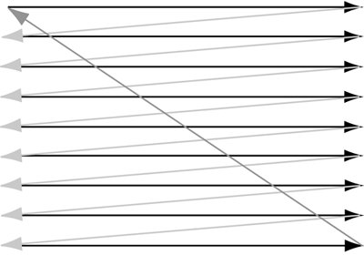
| It is traditional for old timers to regale young-uns with improbable stories of the immense difficulties they faced as young-uns, the better to impress upon young-uns just how cushy their lives are. I shall not refrain from indulging myself in this matter, for indeed, my tales should give pause to younger game designers. The VCS, internally known as "Stella" and designated the 2600, was not the first programmable home videogames machine Fairchild deserves the credit for that. Nor was it the best home videogame machine. However, it had the best combination of getting to market early with good technology, and with strong marketing, it dominated the market. However, its computing and display resources were appalling. Inside was a 6507 processor (a trimmed-down version of the classic 6502) running at 1.2MHz and a special interface chip called the TIA (Television Interface Adapter). It was also equipped with a luxurious 128 bytes not kilobytes, not megabytes, just plain old everyday bytes of RAM. There was no internal operating system of any kind; every scrap of code available to the system had to be inside the plug-in ROM inside the cartridge that the customer purchased and plugged into the VCS. Are you choking on your coffee yet? The worst is yet to come: There was no bitmapped display system. You didn't simply write bits into some bitmap defining the display. Instead, Stella displayed one line at a time, and you changed the line display in real time. To appreciate the trickiness of all this, you must understand the basics of CRT (cathode ray tube) operation. The CRT operates by shining a beam of electrons onto a special surface on the inside of the screen. The electrons hit the surface and excite the atoms there, causing them to emit light. The image is built up in three ways:
Now, the timing of all this is critical. In the VCS, each horizontal line took exactly 76 machine cycles of CPU execution time; vertical blanking was much longer, giving you about 3000 machine cycles. You programmed the display by loading up the TIA with data for the contents of one scan line. It transferred that data from its input registers to its internal buffer and then sent the signal out to the television. While it was busy doing this, you could reload the data registers with the display data for the next scan line. However, you had only 76 machine cycles to do so; this didn't permit a lot of time for snazzy display calculations. The entire display data structure for the VCS was as follows:
Thus, to put a display up on the screen, you had to write a tight little routine called the kernel that stuffed information into the various data registers of the TIA, keeping track of which scan line you were on and changing the values as the beam moved down the screen. If you wanted a more intricate display, you'd need to change the registers more often, which required more machine cycles. But if you took more than the maximum of 76 cycles per scan line, your display would get out of synch with the television, and the screen would turn into pixellated garbage. Most VCS programming was a battle to squeeze maximum display intricacy into 76 cycles, and VCS programmers knew the cycle counts of all the 6502 instructions by heart. It was part of the daily office routine to hear an anguished cry from an office down the hall: "77 cycles!" another programmer would have to completely redesign his kernel. (Actually, there were not one but two female VCS programmers at Atari during my tenure there: Carol Shaw and Carla Meninsky.) So I hope that you're properly impressed with just how hard it was to design games back in those days. Did I mention that we had to walk twelve miles through the snow to get to work each morning? |
EAN: 2147483647
Pages: 248
