Fault-Tolerant Topologies
|
Some networks are more important than others. Of course, all networks are important, right? However, in some situations network availability (or the lack thereof) can be much more costly. When designing networks, there are many features that when used can significantly increase fault tolerance and decrease the possibility of network outages. Perhaps you have worked with servers that included disk mirroring, RAID, or even redundant servers. That is one form of protection. This section will discuss techniques that ensure that first, hosts can find a path to the internetwork, and second, once they find a path, the path actually works!
Redundant LAN Configurations
It does little good to install routers at the access level if the workstations cannot find and use them. This leads you to investigate how different workstations find routers that lead to the internetwork, and how you can help those workstations find redundant paths out of the LAN.
For instance, most network administrators have configured a default router (or default gateway) on a host when setting up TCP/IP. This, along with IP address, subnet mask, and perhaps DNS server, is standard when configuring any TCP/IP device.
Consider the network illustrated in Figure 5.5. Workstation A and Workstation B are assigned the default gateway of 172.16.10.1. ServerA, which has two NICs, also gets a default gateway of 172.16.10.1. Workstation C, however, must be assigned a default gateway of 172.16.20.1, which is the first (and only, in this diagram) router that it sees. It cannot contact the router at 172.16.10.1 directly because they are on separate data link networks! Once the administrator has this all mapped out, he can configure all of the devices with TCP/IP information.
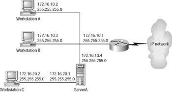
Figure 5.5: A sample internetwork
Some implementations of TCP/IP will allow for multiple default gateways, while others provide for the workstation to listen to routing updates to learn of routers. Any of these methods will provide the client with redundant paths out should the primary router fail, and redundancy should be considered when available. Unfortunately, the most common method of default router configuration is to statically assign the default router at the client. This means that should the router fail, there are two options: fix the router or reconfigure the workstation. Hardly fault tolerant! There are two Cisco solutions to this problem: HSRP and proxy ARP support.
HSRP
HSRP stands for Hot Standby Router Protocol. HSRP can allow IP devices to keep working through their default router even when that router fails. It does this by creating what Cisco calls a phantom router on the network. This phantom router does not exist physically, but it has a MAC address and an IP address. Workstations are configured to use the phantom router’s IP address as a default gateway. The phantom address is actually passed among the physical routers participating in HSRP. If the physical router hosting the phantom router’s MAC and IP addresses fails, another physical router will automatically answer to the phantom’s MAC and IP address and accept the traffic. The workstations need never be aware that the hardware they are talking to has changed, and the MAC and IP addresses they have been using continue to function as if nothing has ever happened!
Figure 5.6 is a diagram of the network from the workstation’s view. It is a logical, not physical, diagram. The workstation believes that there is a single router connecting it to the larger internetwork. It is configured with the IP address of this router for use as a default gateway.

Figure 5.6: An HSRP example—logical
However, the actual hardware looks a bit different, as shown in Figure 5.7. There are actually two routers, only one of which is currently answering to the phantom router’s MAC and IP addresses. The two routers in Figure 5.7 must communicate to ensure that the phantom router’s IP and MAC addresses are always available. After configuration, one of the two routers is chosen to be active and the other to be standby. The active router will proceed to answer requests for the phantom router’s IP and MAC addresses. It will also communicate with the standby router using “hello” messages. If for some reason the standby router is unable to communicate using hellos with the active router, it assumes that the active router has failed, and it begins to answer requests addressed to the phantom router’s IP and MAC addresses. The end result is that the workstation ends up with redundant IP paths out, even though it is statically configured to look for a single path out.
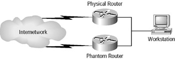
Figure 5.7: An HSRP example—physical
Proxy ARP
Some IP stacks can be configured to take advantage of proxy ARP. You may recall that under normal circumstances, workstations will only ARP for IP addresses that are on their local network. However, when using proxy ARP, these workstations will send out ARP requests for every IP device that they want to communicate with, regardless of whether it is on their local network or not. Any router hearing this request, and able to reach the desired IP address, can respond to the ARP with its own MAC address. From the workstation’s view, it looks like the whole world is one big LAN. The routers take care of the details of reaching remote segments. Proxy ARP is now enabled by default in all Cisco routers.
The end result is that workstations can dynamically locate redundant paths out of the LAN. By sending out the ARP request (which is a broadcast), a response can come from any router able to reach the required destination. Thus if one router fails, the workstation can immediately begin to communicate with the internetwork through any other available routers. You can easily see proxy ARP in action by just setting your Windows machine’s default gateway to be the same as your own IP address and watching it go!
Redundant WAN Connections
As you have just seen, there are several techniques to provide redundancy in the links between clients and servers on the LAN. Now let’s consider ways to provide redundancy inside the WAN.
Consider the network illustrated in Figure 5.8. This is a full mesh network, where every node has a direct link to every other node. For fault tolerance, this is great! However, it is far from efficient and does not scale well. Also, it has departed from the hierarchical topology. However, there is a solution that will preserve hierarchy while providing redundancy in the WAN: a partial mesh topology.
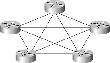
Figure 5.8: A full mesh network
Partial Mesh Topology
A partial mesh has been implemented in the network shown in Figure 5.9. Notice that the hierarchy has been preserved, yet each node has a redundant link to the layer above it. This design provides all the advantages of hierarchical design, is scalable, and can take advantage of load balancing.
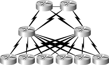
Figure 5.9: A redundant hierarchical network
There are several ways to add the additional WAN connections. They could be added in identical pairs—that is, you could install two T1 lines rather than one. This provides the ultimate in redundancy. If one T1 fails, there is another one waiting to go. However, from a cost perspective this can be similar to buying two new cars just in case one gets a flat tire. True, you will probably never have to walk to work, but that security will certainly cost you.
An alternative to having identical connections to the next layer is to have links that are not the same, that is, perhaps a T1 and a 56K backup line. Should the primary line fail, internetwork connectivity can be preserved, although generally at a reduced level. Once again, cost will most likely determine the capacity of the backup line.
Cisco has a solution that is a special case of this second example, that is, where the two connections are not the same. In this case, the second, or backup, line is not even running until the primary line fails! You will learn about this solution next.
DDR Backup
Not all redundant links have to be dedicated lines. In many cases, an ISDN BRI is used to back up a dedicated leased line. This can be a great advantage, because you will probably not want to bring the ISDN up unless the primary line fails (or becomes overloaded). Cisco’s DDR (dial-on-demand routing) allows this configuration. The ISDN line can be configured to come up only when the primary line either fails or is under heavy load. Of course, should the primary line fail and you have to depend on your backup, you will likely not have the same bandwidth available that you normally do. However, you will probably be paying significantly less than you would to have a pair of dedicated lines.
| Tip | DDR configuration is covered in greater detail in the CCNP/CCIP: BSCI Study Guide, also by Sybex. |
Performance: Load Balancing
Redundant links are not cheap to operate, but in some situations they are called for. If you are going to pay for redundant links, you would likely want to use both lines when they are both available, and that brings us to load balancing.
With most IP routing protocols, load balancing is automatic. Dynamic routing protocols are supposed to find the redundant paths, and dynamic IP routing protocols will use both available paths. However, this is not always a good thing.
Difficulties can arise when the multiple paths out do not have the same bandwidth or cost. Suppose that you have a T1 and a 56Kbps line (for backup) connecting your access layer router into distribution layer routers, as shown in Figure 5.10.
Figure 5.10: Pinhole congestion
Some routing protocols (for example, those that use hop count) could see these two paths and load balance across them just fine until the 56K is full. At that point, the load is equally balanced. However, these protocols are not smart enough to realize that over 90 percent of the total bandwidth is going unused on the T1! Once any link is operating at capacity, these routing protocols are not capable of sending additional traffic across links still not at capacity, because they do not understand capacity as a metric. This problem is called pinhole congestion and is avoided by using advanced routing protocols such as Enhanced IGRP.
|
EAN: 2147483647
Pages: 201