Modeling the Car Body
|
| < Day Day Up > |
|
We propose that you model the car body using Bezier curves with a subsequent conversion to Bezier patches. We selected this method to demonstrate how this can be done. Principally, the shape is rather simple, since Giugiaro used straight lines and basic geometric shapes when designing the car body. Thus, you can model the car body by stretching polygons and moving the cube vertices. If you agree that this method is simple, create a model using this technique.
The modeling itself requires drawing the contours by curves and creating patch objects based on them. All stages of the modeling process are shown in Fig. 15.5. In these illustrations, we have intentionally made the sketches invisible. We won't concentrate on the details of creating geometry; instead, we will provide only general recommendations.
-
It makes sense to model only half of the object. Later, you can create the second half by making a mirror copy and attaching it to the initial half.
-
Don't try to model the whole object as a single shape. Details, such as bumpers, can be created later.
-
If you selected the first method of modeling (using projections as background), you'll have to work in side views. If you selected the second method, it is convenient to work in the perspective or user views in the final stages. Still, most of the work is performed in side views.
-
Switch on the snap to vertices:
-
Main menu à Customize à Grid and Snap Settings
-
-
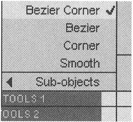
Draw open polygons rather than curves, since the curvature can be added later by changing vertex types.
-
You often will have to select more than one vertex at a time, with coinciding coordinates. To simplify this task, go to the control panel and set the Area Selection checkbox.
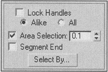
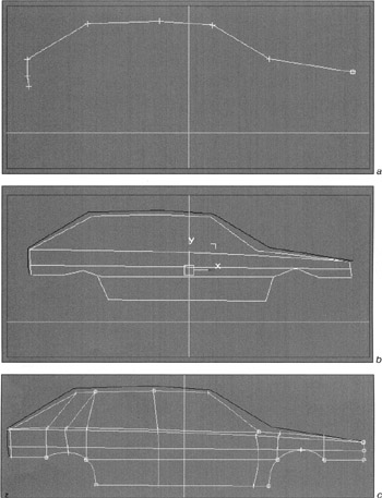
Figure 15.5, a-c: Sequence of modeling the car body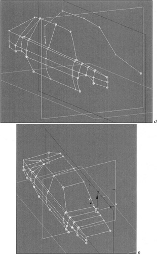
Figure 15.5, d and e: Sequence of modeling the car body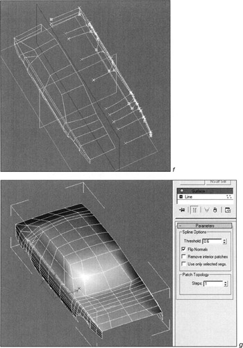
Figure 15.5, f and g: Sequence of modeling the car body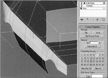
Figure 15.5, h: Sequence of modeling the car body -
When editing vertices, 3ds max will periodically prompt you to Weld coinciding vertices. Don't be deceived; ignore these prompts.
-
Since the accuracy of the sketch itself and the precision of its display in 3ds max viewports are far from perfect, try to use the same view (for example, the left view) as the basic one. Furthermore, specify the maximum possible quality for texture display in the viewports:
-
Main menu à Customize à Preferences à Viewports à Configure Driver
-
-
If you are using planes, you can always move them along longitudinal axes to make the modeling process more convenient.
-
At a certain stage of your work, you'll have to join all the curves to a single object to take advantage the capabilities of curve editing. To do so, select any curve and join all other curves to it. This action is also required to apply the Surface modifier:
-
Control panel à Geometry rollout à Attach Mult
-
-
You'll get a frame consisting of quadrangular and triangular "cells." Only then will the Surface modifier build the patch model correctly.
-
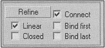
It is convenient to use the Refine command to join the obtained vertices.
-
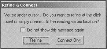
Sometimes it is necessary to start or finish either separating or joining in the existing vertices. In such a situation, you'll be warned that you are attempting to separate the edge in the vicinity of the existing vertex. Select the Connect Only option.
-
After you convert the model to the Editable Patch type or apply the Edit Patch modifier, work on the smoothing groups to obtain the correct model.
Note There is another excellent feature that lets you create curves in any vector graphics editor and import them as curves into 3ds max. If you decide to do so, use Adobe Illustrator (version AI 88) or DWG/DXF formats. Note that AI 88 format can't always be loaded successfully. The import procedure could fail because of the decimal separator, which must be a period. Sometimes the success or failure of this operation depends on the operating system. (This happens occasionally under Windows 98 for unknown reasons.) Finally, note that the vector graphics software must perform the export operation correctly. We use Xara X and, usually, everything goes smoothly. Generally, we also can import successfully files saved in Adobe Illustrator. You should note that the format version supported by 3ds max is AI 88.
-
Save your model. The results of our work are presented in the file named
 lesson15-05.max on the companion CD-ROM. (You can find this file in the \Lessons\Lesson15\Scenes\ folder.) The lesson15-03.max and lesson15-04.max files contain the intermediate variants.
The geometry of the model is now ready. We recommend that you accomplish all other tasks with materials that are combined using masks.
|
| < Day Day Up > |
|
EAN: N/A
Pages: 136