Lesson 9: Modeling the Living Room
|
| < Day Day Up > |
|
Room Modeling
A sketch of a room, indicating dimensions, is shown in Fig. 9.1. Let's start modeling.
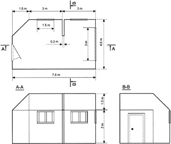
Figure 9.1: Room sketch
First, we should specify the measurement units. Unlike the previous project, where measurements were used mainly for the sake of convenience, precise linear dimensions here will ensure correct lighting calculations.
-
Specify the measurement units (Fig. 9.2, a and b):
-
Main menu à Customize à Units Setup
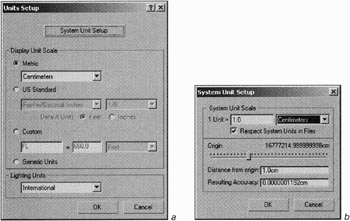
Figure 9.2: Display (a) and system (b) measurement unitsNote Generally speaking, the developers of 3ds max recommend that you retain the system unit settings to avoid inconsistencies when other objects are loaded. In this case, you will work with the units you specify for the Display Unit Scale.
-
-
Set the Grid Spacing to 10.0 cm and Snaps to Grid Points (Fig. 9.3, a and b):
-
Main menu à Customize à Grid and Snap Settings à Home Grid and Snaps tabs
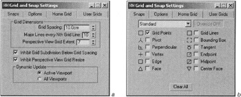
Figure 9.3: Home Grid (a) and Snaps (b) parameters -
-
Create a 750 × 450 cm rectangle in the Top view:
-
Main menu à Create à Shapes à Rectangle
Tip Create the rectangle by entering its parameters via the keyboard (Fig. 9.4). Position the center of the rectangle so that its bottom left corner in the Top view is at the coordinate origin, this will simplify further editing.
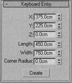
Figure 9.4: Rectangle parameters -
-
Convert the rectangle to an Editable Spline:
-
Context menu à Convert to à Convert to Editable Spline
-
-
Activate the Snaps (<S> key).
-
Make a bevel by selecting the top left corner and inserting vertices on the edges it joins. Delete it (Fig. 9.5, a—c) and convert the remaining vertices to the Corner type:
-
Context menu à Sub-object à Vertex
-
Context menu à Refine à insert vertices
-
Select the corner vertex and delete it (<Del> key)
-
Select all vertices (<Ctrl>+<A> key combination)
-
Context menu à Corner (the cursor should be on one of the selected vertices)
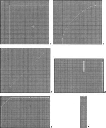
Figure 9.5: Room editing -
| Note | From now on, we will not describe operations in such detail. We recommend that you use hotkeys. Sub-objects are navigated using the <1>, <2>, etc., keys. Pressing a key twice (or <Ctrl>+<B>) ends your work with sub-objects. The selection mode is changed with the <Q> key, moving mode — <W>, rotation mode — <E>, scaling mode — <R>. |
There is another way to make the bevel: select the corner vertex and use the Chamfer command (150 cm) on the control panel.
![]()
Create a partition:
-
Create a rectangle as shown in Fig. 9.5, d:
-
Context menu à Create Line
-
Build the new vertices by clicking the left mouse button
-
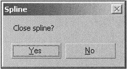
Return to the starting point, and answer "Yes" to "Close Spline?"
-
Exit line creation by clicking the right mouse button
-
-
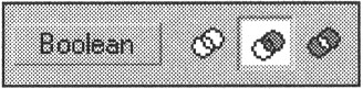
In spline mode (<3> key), select the main spline and subtract the rectangle out of it (Fig. 9.5, e):
-
Control panel à Geometry à activate "Boolean Subtraction"
-
Press the Boolean button and select the rectangle to be subtracted
-
-
Insert two vertices on the edge opposite the partition; this will simplify further editing (Fig. 9.5, f).
The next step requires some explanation. It may seem that we only need to Extrude our plan and invert the normals for our room to be ready. Unfortunately, when external daylight is used, unpleasant "glowing" artifacts appear in the corners of the room. It comes from an error in modeling shadows from an external light source. To prevent that, add outer contours to the walls. If you don't believe us, try it yourself — maybe you'll have better luck.
-
Create the outer contour around the room (Fig. 9.6):
-
Context menu à Create Line
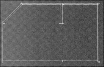
Figure 9.6: Room with outer contour -
-
Extrude the walls 200 cm (Fig. 9.7, a):
-
Main menu à Modifiers à Mesh Editing à Extrude
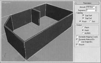
Figure 9.7, a: Creating the walls, window and door openings, and partitionNote Do not forget about the different viewport display modes and how to switch between them (<F2>,<F3>,<F4>). Use whatever is most convenient.
-
-
Convert to an Editable Poly:
-
Context menu à Convert to à Convert to Editable Poly
-
-
In polygon mode, select the upper polygon and Extrude it 150 cm (Fig. 9.7, b):
-
Context menu à Extrude rectangle
-
Enter 150 in the corresponding dialog and press OK
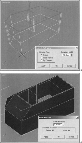
Figure 9.7, b and c: Creating the walls, window and door openings, and partition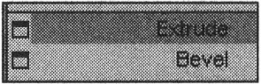
Note "Rectangles" that open settings dialogs are available for many commands. They are considered in detail in the first project.
-
-
Create slants by moving vertices. Weld vertices where necessary (Fig. 9.7, c).
| Tip | This is easy to do by selecting all of the vertices and opening the Weld command settings dialog. Increase the Weld Threshold until all necessary vertices are joined, but don't go too far and weld excess vertices! |
| Note | These manipulations may create strange polygons. At first, we had a triangle overlapping the ceiling diagonally. Don't panic! Just like other 3D packages, 3ds max does not "like" multi-angular polygons. One solution is to select all of the polygons and retriangulate (Control panel à Edit Polygons à Retriangulate). This functions works quite well, and the polygons that result should be more intuitive. If there is still something wrong, you probably made an error somewhere. |
Now; it is time to make the windows and doorways. We suggest that you make them via Boolean Subtraction. In versions of 3ds max before version 5, Boolean operations were implemented poorly. If you are acquainted with our book "3ds max 4: From Objects to Animation," you might have noticed that we never mentioned them. After considerable complaint, 3ds max finally solved a lot of the problems, making Boolean operations much safer to use, even if in most cases you can do without them. We still recommend avoiding them, where possible.
There are three ways to apply logical operations to objects in 3ds max. First, you can create a Compound Object based on one of the operands. This method is good when you have to retain integrity in the objects and operands (e.g., for further animation). The second method applies the Collapse utility. The third one writes a "$object1 — $object2" command in the MAXScript Listener line, where "object1" and "object2" are the names of the objects. Since we do not have to be particularly safe in this case, we will use the second method:
-
Create objects for the windows and doorways — we used a simple Box — and position them appropriately (Fig. 9.7, d). It is important that the boxes intersect both the inner and outer walls; otherwise, you will get cavities instead of openings.
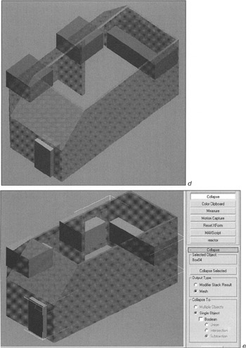
Figure 9.7, d and e: Creating the walls, window and door openings, and partitionNote If you do not plan to open the door, then you do not need to make the doorway.
Tip Sometimes, it is useful to hide other objects while editing (<Alt>+<X> key combination).
-
Select all of the boxes you created by holding the <Ctrl> key and Collapse them with the parameters shown in Fig. 9.7, e:
-
Control panel à Utilities à Collapse à Collapse Selected
-
-
Select the room and "openings" while holding the <Ctrl> key, change the parameters as shown in Fig. 9.7, f, and press the Collapse Selected button again.
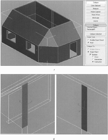
Figure 9.7, f and g: Creating the walls, window and door openings, and partition -
This will result in an Editable Mesh object. Convert it to an Editable Poly.
Now, we have walls with window openings and a doorway. But where is the floor and ceiling? You can create boxes for them, but this is not the best solution: It complicates the Radiosity calculation if the floor and ceiling are not joined perfectly. We have also forgotten the top part of the partition.
First, let's finish the partition:
-
Select and delete the polygons shown in Fig. 9.7, g. (Earlier, we added two vertices to the opposing wall to simplify this operation.)
-
Create polygons for the top part of the partition (Fig. 9.7, h):
-
Context menu à Create
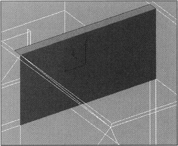
Figure 9.7, h: Creating the walls, window and door openings, and partition -
The following operations require some explanation. They are intended to kill two birds with one stone: first, to create polygons for the ceiling and floor defined by "open" edges (Border); second, to separate the outer and inner surfaces and assign them to two different objects, which will help optimize calculating global illumination.
-
Select the polygons joining the outer and inner surfaces — those at the top and the bottom, as well as those in the window and door openings (Fig. 9.8, a—c).
Tip The Ignore Backfacing flag on the control panel may be useful here.
-
Delete the selected polygons. This will divide our model into two elements. You can check this by switching to Element editing mode and selecting the outer and inner walls. If all surfaces are selected, you missed something.
-
Switch to open edges selection mode (Border).
-
By selecting the open edges and applying the Cap command, you will create both the floor and the ceiling, exactly matching the shape of the walls (Fig. 9.8, d). You will also need to make the roof above the ceiling and the surface below the floor.
-
Position the exterior polygons to create a "shell" that will block light from outside (Fig. 9.8, e).
-
Select the outer Element, Detach it, and rename it Outer Walls (Fig. 9.8, f). Later, you can Hide it to make the editing of other objects easier.
-
Select the inside and rename it Inner Walls.
Do it yourself To make the room more realistic, you might want to bevel the corner joining the walls with the partition (by no more than 5–10 mm). It is easy to miss this when beginning, but slight adjustment considerably enlivens the image.
-
Save your result. You can find ours on the CD-ROM in Lessons\Lesson09\Lesson09(room).max.
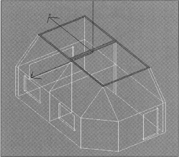
Figure 9.8, a: Final development of the room geometry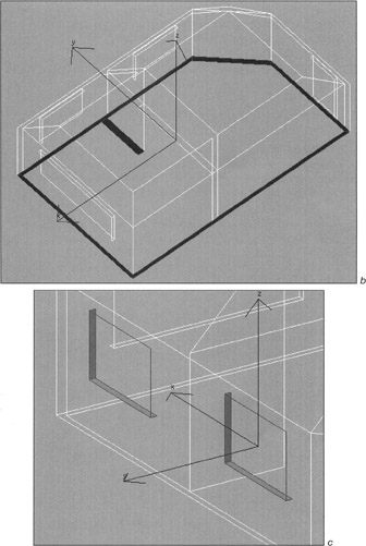
Figure 9.8, b and c: Final development of the room geometry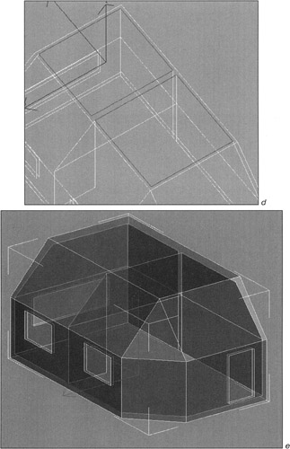
Figure 9.8, d and e: Final development of the room geometry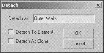
Figure 9.8, f: Final development of the room geometry
|
| < Day Day Up > |
|
EAN: N/A
Pages: 136