Landing on the Moon
|
| < Day Day Up > |
|
For this fragment, you will have to build the scene with the rendering result shown in Fig. 6.10.
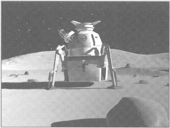
Figure 6.10: Scene for the Moon landing
The building of this scene took more time than that of the previous one. You can find our scene in the ![]() lesson06(part2).max file on the CD-ROM in the Lessons\Lesson06\Scenes\ folder.
lesson06(part2).max file on the CD-ROM in the Lessons\Lesson06\Scenes\ folder.
First the moonscape must be created. You can create it as a single object, but we propose another solution. There is no need to make everything "life-like." Detail is important for objects close to the viewer but not for remote objects. If you don't plan to reach mountains on the horizon, you don't have to create them life-size at such a distance - reducing them will do. Various methods (e.g., configuring the textures) can make the viewer believe that the mountains are really high and remote.
| Tip | To estimate the scale correctly, create an object (e.g., Box) at the coordinate origin with the approximate dimensions of the lunar module (e.g., 5 × 5 × 5 meters). It is convenient to do this by entering the dimensions from the keyboard. 3ds max supports automatic conversion of the units: Enter the dimensions as 5m, and 3ds max will convert them into the current units. |

Create an object to simulate the mountains on the horizon; we named our object Mountains. We propose using a Compound Object of Terrain type, which provides surfaces by curves. The main purpose of this object is to build terrains using isolines of equal heights. We use it slightly differently.
-
Make two concentric circles on the Top view - the Donut type will do. Make the radius of the internal ring approximately 100 m, and the external one 300 m (Fig. 6.11, a).
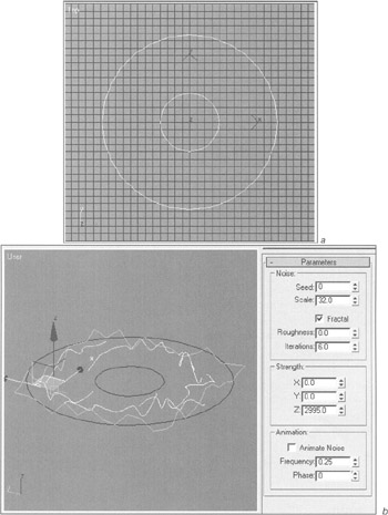
Figure 6.11, a and b: Modeling mountains on the horizon -
Create intermediate forms for future "ridges" and "ravines" between the internal and external circumferences using Line curves. Make more intermediate vertices!
-
Attach all lines to one.

-
Select all vertices and Smooth them:
-
Context menu à Smooth
-
-
Apply the Noise modifier (Fig. 6.11, b):
-
Main menu à Modifiers à Parametric Deformers à Noise
-
-
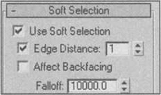
Convert the object to an Editable Spline and work out the vertex level. In particular, move the extreme vertices closer to the zero level of the future terrain.
| Tip | Use Soft Selection. |
Select the Donut01 object and split it into many segments. It is convenient to do this using the Normalize Spline modifier. To control the process, use the Edit Spline modifier on the level of vertices (Fig. 6.11, c):
-
Main menu à Modifiers à Patch/Spline Editing à Normalize Spline, Edit Spline
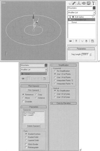
Figure 6.11, c and d: Modeling mountains on the horizon
Now, everything is ready for the terrain creation.
-
Select the Donut01 object, toggle the control panel to object creation mode (Create), and make the Compound Object of Terrain type:
-
Control panel à Create à Geometry à Compound Objects à Terrain
-
Press the Pick Operand button and click the left mouse button on the object-lines forming the terrain.
-
-
Toggle the control panel to edit mode (Modify tab) and specify the parameters as shown in Fig. 6.11, d.
| Explanation | Rename the object Mountains. After you turn to Sub-object editing and select the operand from the list, you can edit the operand by moving down the stack. This feature is typical for most compound objects. Select the Graded Surface type in the Form group. In the Simplification group, select a value making the mesh of the object more or less uniform. This is important for further smoothing. Leave the rest of the parameters unchanged. Try to find out yourself what they are intended for. (This is easy.) |

The result is a rather crude model. Let's complicate it and smooth it a little. In general, you can use the MeshSmooth modifier, but this provides a regular mesh.
We propose using the Hierarchical SubDivision Surfaces (HSDS) modifier. This modifier lets you perform adaptive splitting.
-
Apply the HSDS Modifier:
-
Main menu à Modifiers à Subdivision Surfaces à HSDS Modifier
-
-
Apply adaptive splitting to the object with the parameters shown in Fig. 6.11, e:
-
Control panel à…à Advanced Options à Adaptive Subdivision
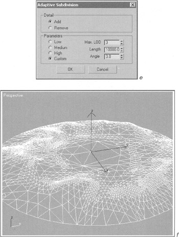
Figure 6.11, e and f: Modeling mountains on the horizon -
| Explanation | Three settings offered by the developers were not useful to us, so we substituted them for Custom settings. We set the maximal level of splitting, or detail to 3 (Max. LOD), which is enough. By setting the maximal value in the Length parameter, we determine the minimal length of the edges for which splitting can be done and avoid splitting the known flat planes. We set a small value for the Angle parameter to determine the minimal angle between the planes for which splitting can be done. |
The mountains are ready (Fig. 6.11, f).
We propose modeling the part of the terrain closest to the viewer using Displacement. To do so, use the Plane primitive and the texture on the Displace channel.
| Note | We considered this process in detail in our book "3ds max 4: From Objects to Animation." |
-
Create the Plane primitive at the coordinate origin with the approximate dimensions of 200 × 200 meters. To do this, use the keyboard (Fig. 6.12, a).
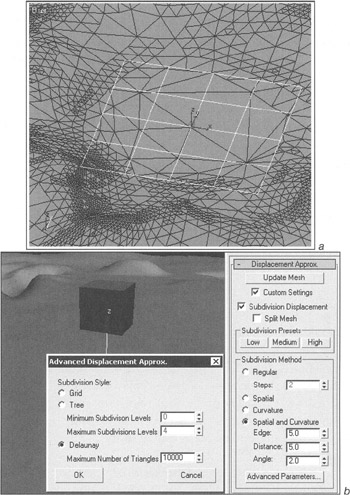
Figure 6.12: Terrain blanks (a) and parameters of the Displace Mesh modifier (b) -
In the object's parameters, check the Generate Mapping Coords flag and rename it Ground.
-
Open the material editor (<M> key) and select any preview window.
-
Specify the raster image (Bitmap) as the Displacement map in the Maps rollout. Select the
 Land-displace.tga file on the CD-ROM in the \Lessons\ Lesson06\Scenes folder.
Explanation Although the displacement texture may have any color depth, it is more convenient to use an image made in 256 grayscale (Grayscale). The brighter areas will be those with greater convexity; the darker areas will be those with deeper indention. Note that when the chart of vertices is created, the zero level is marked with a gray, not black, color. This will be helpful as you draw convex and concave figures on the surface.
-
Assign the material to the object.
So far, you cannot see your terrain in the viewport. To do this, it is necessary to apply the Displace Mesh modifier. The application of the Displacement map is mainly intended for the object's complication during rendering. We need it to use the terrain at full resolution in the viewports.
-
Apply the Displace Mesh modifier:
-
Control panel à Modifier List à Displace Mesh
-
-
Specify the parameters so the object corresponds to the chart of vertices. Don't forget that you will place the camera in immediate proximity to the surface, so it is necessary to obtain the best quality possible (Fig. 6.12, b).
It will be helpful to select the parameters of the modifier and of the material on the Perspective view next to the pivotal object created at the beginning. For example, we reduced the height of the displacement by setting the level value (Amount) to 50 in the material's parameters. To follow changes in the viewport, it is necessary to press the Update Mesh button in the parameters of the Displace Mesh modifier.
After the parameters of the Displace Mesh modifier are specified, convert the object to the base Editable Mesh type. To do this, open the modifiers' stack context menu by clicking the right mouse button on the Displace Mesh Binding modifier in the stack and by selecting the Collapse To command. Remove the texture from the Displace channel; we don't need it anymore.
Before modeling, we looked through the photographs of the Moon's surface. We could see pebbles of various sizes densely covering the surface. Let us also "scatter" a couple of dozen of pebbles of various sizes. To do this, we propose using another compound object - Scatter.
-
Create a pebble. This is a simple geosphere with the approximate diameter of 0.5 m rumpled with the Noise modifier (Fig. 6.13, a).
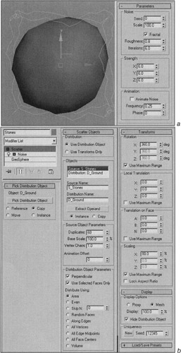
Figure 6.13: Creation of pebbles on the Moon's surface -
Create a compound object (Compound Objects) of the Scatter type, keeping the selection on, with the parameters shown in Fig. 6.13, b:
-
Control panel à Create à Geometry à Compound Objects à Scatter
-
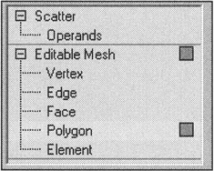
| Explanation | In the Pick Distribution Object rollout, set the toggle in the Copy position to keep the original object independent. (It will still be of use.) Select the Ground object as the one the pebbles will be "scattered" on. Set the number of copies (Duplicates) to about 60. Use the Vertex Chaos parameter to obtain inequality of the pebbles. Set the Distribute Using toggle in the Area position. The Use Selected Faces Only flag restricts the distribution area. To use it, select the planes of the objects on the surface of which the pebbles will be distributed. You can do this before creating the Scatter object or directly within it. Go down the stack to the level of the sub-objects - operands and select the D_Ground operand. Go down the stack, select the required polygons, then go back to the Use Selected Faces Only level under the Scatter object. In the Transforms rollout, specify the values for rotating and scaling the distributed object. This will diversify the appearance of the pebbles even more. Deactivate the display of the D_Ground object in the Display rollout (Hide Distribution Object flag). |
Now it is time to go for the materials. But first you must set a source of light (to simulate the Sun) and the camera.
-
Set the source of light as shown in Fig. 6.14, a. Specify its parameters according to Fig. 6.14, b..
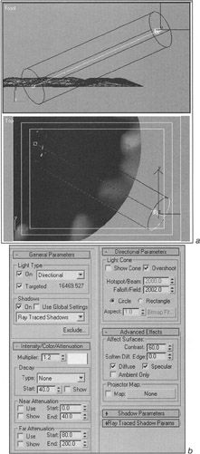
Figure 6.14: Position (a) and parameters (b) of the light sourceExplanation The type of the source is Targeted Directional.
The type of shadows is Ray Traced (with value of the Multiplier slightly bigger than the default); the color is yellowish. Set the Falloff/Field parameter so that the central part of the terrain is within its view. The shadows are appropriate here.
The Overshoot flag will light all objects despite the Falloff/Field value, but there will be no shadows. The surface is quite even, so nobody should notice their absence, and you will save hours at the final rendering.
Increase the Contrast to 60.
-
Create the Target Camera on the Top view and position it so that the object substituting the lunar module is within the view. The target of the camera must be in the center of the object (Fig. 6.15, a and b). Use the Safe Frame.
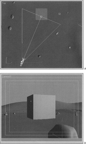
Figure 6.15: Camera position (a) and the camera view (b)
| Tip | Create and place a big pebble on the foreground; it will provide an additional feeling of depth. |
The Ground and Stones material of the foreground objects should create the illusion of an uneven surface covered with a layer of dust. The material of the mountains should create the illusion that the mountains are far from the viewer. Unfortunately, there is no atmosphere on the Moon. Therefore, we cannot apply the standard method - haze.
All textures for these materials will be procedural. During the setting of the materials, you will have to perform many test renderings, but it can't be helped; the procedural textures are displayed incorrectly in the viewports.
-
The material structure for the Ground and Stones object is shown in Fig. 6.16, a.
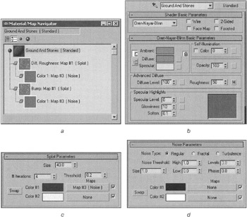
Figure 6.16: Ground and Stones material structure (a), material parameters (b), and texture parameters (c and d)
| Explanation | Select a shader of the Oren-Nayar-Blinn type. Leave the default - gray - color (Fig. 6.16, b). In addition, make the Specular color gray, but lighter. This will help you to avoid certain troubles with the Oren-Nayar-Blinn shader type. Apply the texture of the Splat type on the Bump channel. Change the color of the texture to black-and-white. Select a size that shows rounded convexities in the foreground during rendering (Fig. 6.16, c). Apply texture of the Noise type on the channel for one of the colors. Select a size and type that achieves the illusion of dust during rendering (Fig. 6.16, d). Reduce to 10 the level of the texture affection (Amount) on the Bump channel in the parameters of the materials. Transfer this texture to the Roughness channel using the Instance method and reduce the Amount parameter for this channel to 20. This will help you to obtain an uneven surface. |
The material for the Mountains object is based on the previous material. Transfer the Ground and Stones material in any free preview window of the material editor and rename it Mountains.
The structure of the material is shown in Fig. 6.17, a.
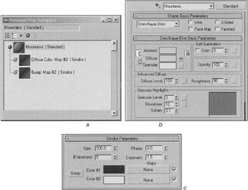
Figure 6.17: Mountains material structure (a), material parameters (b), and texture parameters (c)
| Explanation | In the main parameters of the material, make the colors on all channels lighter and yellowish to create illusion of depth (Fig. 6.17, b). Apply the procedural texture of the Smoke type on the Bump channel and select the size to obtain mountain ridges (Fig. 6.17, c). Transfer the same texture on the Roughness and Diffuse Color channels and set the Amount values for these channels at 20 and 5, respectively. |
| Note | Do it better, if you can! Don't forget to experiment; this is the only way to master the minute details of 3D animation. |
Now, it is time to merge the lunar module into the scene. You can use either our ![]() Lesson06(Lunar-Ship).max file in the \Lessons\Lesson06\Scenes folder, or your own module:
Lesson06(Lunar-Ship).max file in the \Lessons\Lesson06\Scenes folder, or your own module:
-
Main menu à File à Merge
-
Select all objects in the list and press OK.
Remove the pivotal object (Box01). Place the lunar module by selecting the LUNAR SHIP object and moving it.
Move and rotate the LUNAR SHIP object to make it steady on its props and a little bit buried in the "lunar dust".
When the lunar module is on the surface, we should not neglect the glow from reflected light on the surface. To simulate such light, place several omnidirectional, low-powered light sources (Omni) under the surface - without shadows and affection on the flash channel (Specular) of the material. Set attenuation (Far Attenuation parameter) so that no mountains on the horizon are lit (Fig. 6.18).
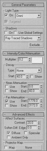
Figure 6.18: Parameters for simulating the light reflected by the Moon's surface
Now, the time for animation has come.
-
Specify the parameters of the time scale. Set the picture frequency to 15 frames per second and the length to 12 seconds.
-
Link the target of the camera with the LUNAR SHIP object to make the camera follow the lunar module.
The scene appears rather ponderous. To avoid troubles, it is better to simplify it by hiding some of the objects.
-
Select the Mountains, Stones, and Living Module objects, then hide them:
-
Context menu à Hide Selection
-
-
Select the Ground object on the Top view. (This object is of the Editable Mesh type.) Select the polygons inside the landing site, invert the selection (<Ctrl>+<I>), and hide them:
-
Control panel à Hide

-
Now the position of the lunar module corresponds to the final one. It would be unreasonable to set it anew.
-
Open the Set Key Filters window and select the Position and Custom Attributes flags (Fig. 6.19). These parameters will be animated. There is no need to set the animation keys for the others.
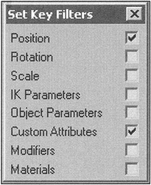
Figure 6.19: Set Key Filters window -
Go to the frame 0:9:0 (9 seconds), press the Toggle Set Key Mode button, and set the key (Set Key button).
-
Go to the start frame of the animation and raise the lunar module above the Moon surface. Extend the props slightly using the additional attribute of the LUNAR SHIP object, and set the key again.
-
Edit the curves to make the module lose height as it gradually slows down and to make the landing props extend completely at the moment they touch the surface (Fig. 6.20).
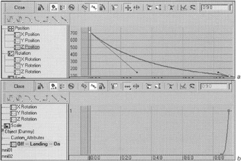
Figure 6.20: Editing the motion curves of the object (a) and the extension of the landing props (b)
| Do it yourself | Experiment with the animation curves of other parameters. For example, you can specify the module's search path during the landing by drawing the keys on the rotation curves in the way it was done in the previous fragment. |
Now, all we have to do is to add "luster" to the scene.
During the flight of an interplanetary station, the exhaust jets of the mid-flight engines would be unavailable. (The engines would start up only at the acceleration and at the moment of placement on the required orbit.) During the landing, however, the engines of the lunar module would work at full power. At the approach to the surface of the Moon, these jets would "blow" the dust off the lunar ground in the landing site. But realistically, smoke or clouds of dust cannot be created in our scene because there is no atmosphere on the Moon, only cosmic cold and vacuum.
We suggest making both of these effects - the engine reactions and the scattered dust and pebbles - using the particle system. Begin by creating the jet from the nozzle of the lunar module engine.
| Tip | To simplify the task of setting the particle system, make it in a separate file. We will show you how to work efficiently in one scene. |
It is convenient to find all objects in the scene. You already have hidden some objects. To unhide only those required, it is worth creating a named set for these objects (Named Selection Set).
-
Select all visible objects and create the set by naming it (e.g., _MAIN OBJECT):
-
Main panel à Named Selection Set + Enter

Note This name also appeared in the drop-down list of the animation panel.
-
-
Hide all objects:
-
Context menu à Hide Selection
-
-
Create the particle system of the SuperSpray type in the Top view:
-
Main menu à Create à Particles à SuperSpray
-
-
Set the parameters of the system as shown in Fig. 6.21, a, to obtain a "fountain" (Fig. 6.21, b).
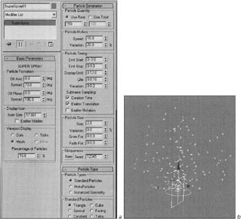
Figure 6.21: Parameters of the SuperSpray particle system (a) and its appearance (b)
| Explanation | The particle system has many parameters. We will describe in detail only those necessary for this lesson. Basic Parameters rollout:
Particle Generation rollout:
Particle Type rollout:
|
Now we have to put the flow of particles into the required shape. It is tempting to use a suitable parametrical modifier-deformer (e.g., Free Form Deformer), and such an option does exist in 3ds max! The modifier can be applied directly, but this will not provide the required result: The modifier will affect the particle emitter but not the particles. 3ds max can convert the system of particles into a geometrical object using a compound object of the Mesher type. This converts the original object into a mesh object that you can manipulate as you like.
-
Create an object of the Mesher type (Fig. 6.22, a):
-
Control panel à Create à…à Compound Object à Mesher
-
-
Toggle the control panel into the Modify mode, press the Pick Object button, and click the left mouse button on the system of particles. The appearance of the object will change, and it will exactly repeat the system of particles (Fig. 6.22, b).
-
Rename the object Jet and hide the system of particles.
You could apply the FFD Cylinder modifier to the Jet object, but this will not produce the required result. The mesh of the modifier is scaled depending on its relationship with the particles. Therefore, you need to use another method.
-
Create an FFD (Cyl) space warp (similar to the modifier of the same name) so that the control Lattice fully covers the Jet object (Fig. 6.22, c):
-
Control panel à Create à Space Warps à Geometric/Deformable à FFD (Cyl)
-
-
So far, the Jet object is "unaware" that the space warp was applied to it. Bind the Jet object to the FFD01 object using the Bind to Space Warp command.

-
Put the flow of particles into the required shape, working on the level of the control vertices of the FFD01 object (Fig. 6.22, d).
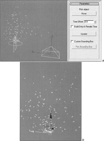
Figure 6.22, a and b: Shaping the flow of particles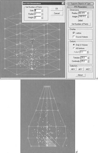
Figure 6.22, c and d: Shaping the flow of particles
The next step is the creation and assignment of the material to the flow of particles. There is a perfect Particle Age texture in 3ds max for the particles that lets you assign, for example, color to the particles depending on their "age." We will use it later to simulate dilution of the dust particles; it cannot be applied now. The reason is simple: The particles, being the part of the Mesher type object, don't "remember" that they are particles. So, we will have to go another way.
-
Open the material editor, select any free preview window, and rename the material Jet.
-
Select Gradient as the texture on the Diffuse Color channel. Specify the parameters of the texture as shown in Fig. 6.23, a.
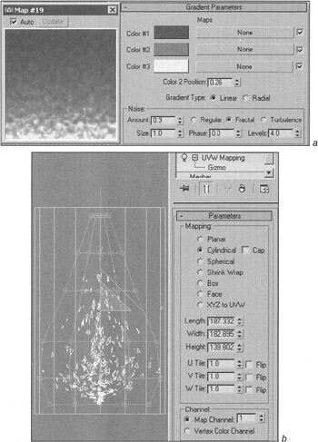
Figure 6.23: Parameters of the material (a) and UVW Mapping (b)Explanation The colors (top-down) are deep brown, vermilion, and canary.
You can obtain a shift in either direction using the Color 2 Position parameter.
Small Fractal Noise will add irregularity to the jet fire. You also can animate the noise phase.
-
In the parameters of the object itself, specify the Self-Illumination value as 100% and check the 2-Sided flag.

-
Assign the material to the Jet object.

Apply the UVW Map modifier to the Jet object. Select the cylindrical type and place the gizmo of the modifier so it fully covers the Jet object (Fig. 6.23, b).
Now you can perform quick rendering. If the scene is satisfactory, leave it as it is. In our scene we had to increase the amount of particles and their size by editing the parameters of the original SuperSpray object. (To do this, we had to display it with the Unhide by Name command.) Then we had to add Object Motion Blur in the parameters of the Jet object. (Image Motion Blur does not work in this case.) This gave us the desired result. We also unchecked the Cast Shadows and Receive Shadows flags in the parameters of the object, which considerably accelerated the final rendering.
Now we have to place the fire.
-
Group the Jet and FFD01 objects to move them together. Select the Jet and FFD01 objects:
-
Main menu à Group à Group à enter Jet Fire à OK
-
-
Unhide the _MAIN OBJECTS:
-
Context menu à Unhide By Name
-
Choose _MAIN OBJECTS in the Selection Sets drop-down menu and press the Unhide button.

-
-
Set the Jet Fire group into the nozzle. Scale it by all coordinates (Uniform Scale), if necessary.
-
Link the Jet Fire group to the LUNAR SHIP object.
Now, put on the final touch. Apply the Glow effect (halo) to the jet fire. This procedure is described in detail in Lessons 5 and 17, so here we will mention only the parameters. Pay attention to the Use Source Color parameter. Set it to 100%, and the color of the halo will correspond to the color of particles (Fig. 6.24).
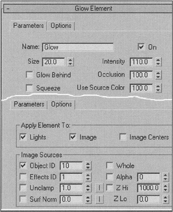
Figure 6.24: Parameters of the halo effect for the jet fire
To create the effect of scattered dust and pebbles, you will have to make two systems of particles. Both will have the same Particle Array type. This type requires an object-emitter, so create one in the landing site of the lunar module.
-
Build a truncated cone in the landing site (Fig. 6.25, a).
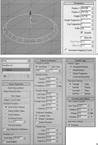
Figure 6.25, a and b: Dust creation and animation -
Rename it Dust Emitter, convert it to an Editable Mest object, then select and remove the top and bottom polygons.
-
Hide all objects except the Dust Emitter:
-
Context menu à Hide Unselected
-
-
Create the system of particles of the Particle Array type anywhere in the scene. Rename it Dust and set the parameters as shown in Fig. 6.25, b:
-
Main menu à Create à Particles à PArray
Explanation Select the Dust Emitter object as the particle emitter and specify the emission of particles on all surfaces of the object.
Set the amount of particles emitted in one frame (Use Rate) to 100. This parameter will be animated according to their distance from the lunar module.
Set the divergence angle of the particles (Divergence) within 20-40°.
Set the time parameters of the particles so that they are emitted and displayed during the whole fragment. Make the life-span of the particles 2-3 seconds. The type of particles should be triangle; their size should be small.
Make the particles spin quickly (Spin Time parameter).
-
-
Open the curve editor and animate the Birth Rate parameter so that the amount of particles gradually increases within a time unit, stays at 200 for some time, then gradually decreases to zero (Fig. 6.25, c). To do this, use the Add Keys and Move Keys tools in the context menu of the curve editor.
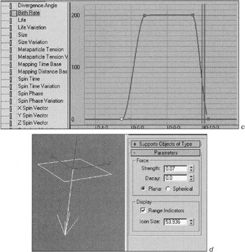
Figure 6.25, c and d: Dust creation and animation
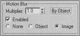
There is no atmosphere on the Moon, but there is gravitation (although less than that on the Earth). Make the particles change their trajectory.
-
Create the Gravity space warp with its vector pointed down:
-
Control panel à Create à Space Warps à Forces à Gravity
-
-
Bind it with the Dust system of particles and set it so the particles changed their trajectory (Fig. 6.25, d). Use the Bind to Space Warp command to link the Dust object to the Gravity object.
You can use the Mountains material as the original material for the dust.
-
Open the material editor.
-
Transfer the Mountains material into any preview window, rename it Dust, and make it double-sided (2-sided).
-
Make the colors a little brighter. You can increase the value of the Self-Illumination parameter to 20-40%.
-
Assign the Particle Age texture as Opacity. Make Color #1 and Color #2 white; this will make the dust opaque at the start of its life. Make Color #3 black; this will make the dust gradually disappear (Fig. 6.26).
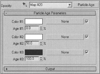
Figure 6.26: Parameters of the Particle Age texture -
Use Image Motion Blur for the dust:
-
Context menu à Properties
-
-
Hide the Dust Emitter object.
-
Duplicate the Dust object and rename it Pebbles. Move the Dust object by pressing and holding the <Shift> key.
-
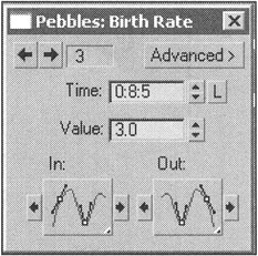
Change the parameters as shown in Fig. 6.27, a.
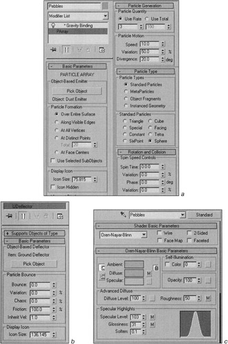
Figure 6.27: Parameters of the particle system (a), deflector (b), and material (c) for the pebbles
| Explanation | Slow the Speed and increase its Variation. Increase the size of the particles and select the Sphere type for them. Deactivate the particle system's rotation around its axis. To change the amount of particles, edit either the animation curves or the parameters of the keys on the time scale. To do this, click on the key with the right mouse button, select Pebbles: Birth Rate in the menu, and edit the key value. |
Make the pebbles remain on the surface of the Moon after they fall. To do this, use a Space Warp of the Deflector type.
-
Create a Universal Deflector anywhere in the scene and Bind it with the Pebbles system of particles using the Bind to Space Warp command:
-
Control panel à Create à Space Warps à Deflector à UDeflector
-
The universal deflector enables you to use the surface of any object as the deflector. In our case, it makes sense to employ the Ground object. But it is very big, and its use will lead to deceleration of the collision handling. We propose that you do the following:
-
Unhide the Ground object, if it is hidden:
-
Context menu à Unhide By Name
-
-
Select the Ground object, go to the polygon mode, and select the polygons around the landing site.
-
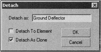
Detach them as a copy (Detach As Clone) named Ground Deflector.
-
In the parameters of the UDeflector object, assign the Ground Deflector object as the deflector. Set the parameters so that the fallen pebbles never rebound or move (Fig. 6.27, b).
-
Transfer the Mountains material into any preview window, rename it Pebbles, and increase the shine a little to create the effect of fused pebbles (Fig. 6.27, c).
Finally, create the stars. To do this, we propose that you use the MilkyWay plug-in from Pavel Kuznetsov. You can find it on the CD-ROM in the Plugins\Ky_MilkyWay5 folder. To install it, copy the ![]() Ky_MilkyWay.dlv file into the \3dsmax5\plugins folder and restart 3ds max.
Ky_MilkyWay.dlv file into the \3dsmax5\plugins folder and restart 3ds max.
-
Activate the MilkyWay effect and specify its parameters (Fig. 6.28):
-
Main menu à Rendering à Effects
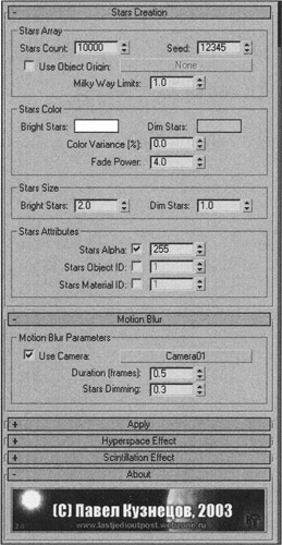
Figure 6.28: Parameters of the MilkyWay effect -
This process provides excellent results, more efficient than those of the method we considered in Lesson 5.
Now everything is ready! Unhide the necessary objects, perform test rendering, and adjust the parameters, if necessary. You can also add the gas jets from the nozzles of the orientation engines. The Reflection channel of the lunar module body materials may be assigned the texture of the Raytrace type using a small value (30-40) for Amount, since we now have something to reflect! You can perform the final rendering of the fragment, if you know how to do this. In Lesson 8, the settings of rendering will be considered in detail.
|
| < Day Day Up > |
|
EAN: N/A
Pages: 136