Propulsion Module Modeling
|
| < Day Day Up > |
|
The propulsion module is modeled using curves.
-
Create a Rectangle in the Top view to match the dimensions of the living area (Fig. 3.8, a):
-
<Ctrl>+Context menu à Rectangle
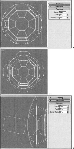
Figure 3.8, a-c: Modeling the propulsion moduleTip There are no guidelines in 3ds max, but they are not necessary because the grid is usually enough. In this case, however, it is convenient to use cross hairs for the cursor (Main menu à Customize à Preferences à General à UI Display à Display Cross Hair Cursor). If you plan to use this option often, you might want to assign a key combination, for example <Alt>+<H>.

-
-
Rotate the rectangle 45° around the vertical axis and convert it to an Editable Spline:
-
Context menu à Convert to à Convert to Editable Spline
-
-
Divide each segment into two equal parts:
-
Context menu à Sub-object à Segment or <2> key
-
Select all segments (<Ctrl>+<A>)
-
Control panel à … à Divide

-
-
Select the resulting vertices and convert them to Bezier:
-
Context menu à Sub-object à Vertex or <1> key
-
Context menu à Bezier
-
-
Bend the segments into curves. To do so, simply Scale the vertices relative to the common center:
-
Context menu à Scale or <R> key
-
Main Toolbar à Use Selection Center

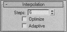
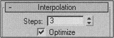
Note 3ds max has one "subtlety" when working with splines, which you probably encountered while scaling the vertices. Although the segments are curves (Curve), they remain straight. Both the explanation and solution are simple - during curve interpolation, by default, segments are optimized to remain straight up to some very small vertex angle. You can activate and deactivate this optimization in the Interpolation rollout. Leave it on for now, because we just began editing and everything might be corrected later by itself. Actually, that is exactly what will happen.
-
-
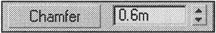
Select the vertices and make chamfers of about 0.6 meters:
-
Control panel à Chamfer
-
-
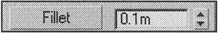
Make Fillets on the resulting vertices:
-
Control panel à Fillet (Fig. 3.8, b)
-
Now, make cavities for the landing props.
-
Create a rectangle with rounded corners in the Top view where the cavity should be.
-
Rotate it so that the landing props can fold easily (Fig. 3.8, c).
-
Duplicate the rectangle (we called it Rectangle01) by turning it 90° around the center of the propulsion module while holding the <Shift> key:
-
Main Toolbar à Reference Coordinate Center à Pick à select Rectangle01
-
Main Toolbar à Use Transform Coordinate Center
-
Rotate the rectangle while holding the <Shift> key
-
Use the Copy cloning type with 3 copies

-
-
Select Rectangle01 and Attach all four rectangles to it:
-
Context menu à Attach
-
-
Select the main spline we created initially and make the cavities from the rectangles using subtraction (Fig. 3.8, d):
-
Context menu à Sub-object à Spline
-
Control panel à Boolean à Subtraction
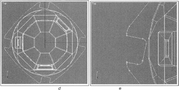
Figure 3.8, d and e: Modeling the propulsion module
-
-
Remove "unnecessary" vertices to simplify the geometry (Fig. 3.8, e). It also makes sense to reduce the number of interpolation steps in the curve's parameters.
-
Create a Circle, then align and attach it to Rectangle01.
-
Hide the living module:
-
Context menu à Hide Unselected
Note Strictly speaking, the editing procedure that follows is not the most efficient. It would be more straightforward to create a surface based on the curves we have already constructed by applying the CrossSection and Surface modifiers. Try to do this, if you understand what we mean.
-
-
Extrude the Rectangle01 object by 1 meter (Fig. 3.9, a):
-
Main menu à Modifiers à Mesh Editing à Extrude
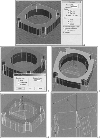
Figure 3.9, a-e: Editing the propulsion module -
-
Convert it to an Editable Poly.
At this point, it would be nice to Bevel the top polygon but. In this case, however, it would cause the polygons to overlap. So, we must take a more difficult route:
-
Select the top polygon and Extrude it by about 0.4 meter (Fig. 3.9, b).
-
Select the edges of the top of the central hole - it must be done manually, because the Loop command does not work for some reason.
-
Scale them relative to the common center (Fig. 3.9, c).
-
Return to polygon editing and reduce the size of the top polygon as required (Fig. 3.9, d).
-
Select the vertices comprising the exterior curve and merge them using the Collapse command (Fig. 3.9 e). Be sure not to include redundant vertices!
-
Merge the vertices one by one with the Target Weld command to obtain proper cavities (Fig. 3.9, f).
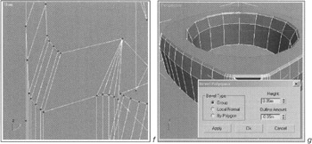
Figure 3.9, f and g: Editing the propulsion module -
Select the top polygon and give it a little facet using the Bevel command (Fig. 3.9, g).
You can make the bottom part in the same way, but there is also a more interesting method.
-
Select the top polygons. To do so, select the top polygon and use the Grow command:
-
Control panel à Selection à Grow
-
-
Create a new object with the Detach command and copy it (Fig. 3.10, a).
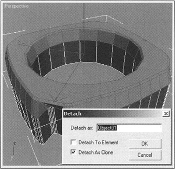
Figure 3.10, a: Editing the propulsion module -
Mirror the resulting object and move it down (Fig. 3.10, b). We are using the Y axis, but you might be working in another view or with different coordinates:
-
Main panel à Mirror
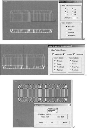
Figure 3.10, b-d: Editing the propulsion module
-
-
To line up the objects precisely, use the Align command (Fig. 3.10, c):
-
Main panel à Align

-
-
Select Rectangle01 again. (Now is a good time to rename it, for example, as Service Module.) Select and remove the bottom polygon, then attach the new object:
-
Context menu à Attach
-
-
Select the vertices on the border of the two elements and Weld them together with a very small Threshold (Fig. 3.10, d).
-
Model the bottom part as in our sketch by selecting and moving vertices (Fig. 3.10, e).
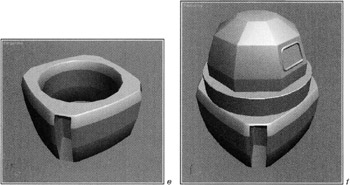
Figure 3.10, e and f: Editing the propulsion module -
Put the final touches on the module by assigning smoothing groups to the polygons.
-
Unhide the Living Module and position the modules next to each other (Fig. 3.10, f):
-
Context menu à Unhide All
-
You can find the result of our work on the CD-ROM in Lessons\Lesson03\scenes\Lesson03-living-and-service-modules.max.
|
| < Day Day Up > |
|
EAN: N/A
Pages: 136