Living Area Modeling
|
| < Day Day Up > |
|
Before you model, specify the units. In the previous lesson, millimeters were used; in this one, we propose that you use meters. Keeping in mind the developers' warning not to change the units without utter necessity, we would still like you to see the effects when they are changed. Setting the units is described in detail in Lesson 2.
-
Create an octahedron with a radius of 2 meters and height of 0.5 meters as the base of the living area (Fig. 3.2):
-
Main menu à Create à Extended Primitives à Gengon
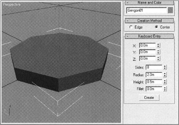
Figure 3.2: Octahedron representing the living areaTip When creating a primitive, it is convenient to enter the necessary parameters using the keyboard.
-
-
Note that the grid pitch is large — 10 meters, which is very inconvenient. Correct this by setting the pitch to 0.1 meter (Fig. 3.3). To make the grid useful in the projection viewport, either uncheck the Inhibit Perspective View Grid Resize flag, or increase the value of the Perspective View Grid Extent parameter:
-
Main menu à Customize à Grid and Snap Settings à Home Grid
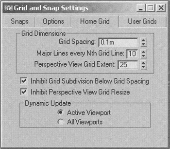
Figure 3.3: Grid pitch setting -
-
Rename the object Living Module and convert it to an Editable Poly:
-
Context menu à Convert to à Convert to Editable Poly
Note The editing that follows may not seem the most direct, but we are using this simple example to demonstrate as many methods as possible of editing polygonal objects. If you want to accomplish the same task in an easier way — do it!
-
Use the central upper vertex of the object to create another integral polygon.
-
Switch to vertex operation mode, select the vertex, and apply the Chamfer command (Fig. 3.4, a). Note that there is a window icon to the left of the command. If you press this icon, the settings window of the command will appear. Such icons are provided for many commands:
-
Context menu à Chamfer icon
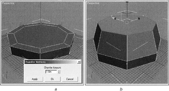
Figure 3.4, a and b: Sequence of creating the living area's basic geometry
-
-
Select the resultant polygon and extend it on the Z axis approximately 1 meter (Fig. 3.4, b). Specify this value on the coordinate entry panel, or enter it directly in the window of the Z coordinate. Offset Mode Transform Type-In should be on.
-
Extrude the polygon by approximately 0.5 meter and make its size comply with that of the docking unit with a diameter of 1.6 meter (Fig. 3.4, c). It is convenient to do so by entering these parameters into the Bevel command:
-
Context menu à Bevel icon
-
Enter 0.5 for Height and press the OK button
-
Use Outline Amount spinner to adjust the size of the grid in Left view
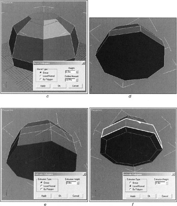
Figure 3.4, c—f: Sequence of creating the living area's basic geometry -
-
Rotate the view in the projection viewport as you like (or use the Bottom view), and select the edges of the bottom polygons.
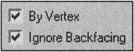
Tip When selecting edges, it is convenient to use the By Vertex and Ignore Backfacing flags. In this case, we can simply click the left mouse button on the central bottom vertex.
-
Remove the edges of the bottom polygons using the Remove command (Fig. 3.4, d):
-
Context menu à Remove
Note Only the Remove command should be used for this purpose! If you use the <Del> key, you will have an unnecessary "hole."
By default, the Remove command has no key combination. It is worthwhile to assign a shortcut, for it often will be useful in modeling polygons (Main menu à Customize User Interface à Keyboard à Remove (Poly)). It would be nice to assign a combination like <Alt>+<Del>. Unfortunately, the <Del> key is reserved in 3ds max, so choose something else (e.g., <Alt>+<End>).
-
-
Select the bottom polygon (now it is the only one) and Extrude it by approximately 0.8 meter (Fig. 3.4, e):
-
Context menu à Extrude icon
-
-
Select the polygons in the circle (marked by white contour lines in the illustration) and Extrude them by 0.4 meter in the direction of the Local Normal by setting the corresponding Extrusion Type (Fig. 3.4, f).
Tip This selection can easily be made as follows: Select one lateral edge, then select all lateral edges using the Ring command of the Selection drop-down menu on the control panel. Convert the selection composed of edges to a selection of polygons using the Convert to Face command on the context menu.
-
Make the bottom round by selecting the edges and applying the Chamfer command twice (Fig. 3.4, g). To stay in the settings window, press the Apply (not OK) button for the first adjustment.
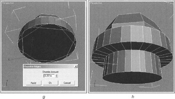
3.4, g and h: Sequence of creating the living area's basic geometry -
Build the bottom part (Fig. 3.4, h) with the Inset and Extrude commands after selecting and removing the unnecessary edges.
Tip This selection can be made as follows: Select the central polygon, use the Convert to Edge command on the context menu, expand the selection by pressing the Grow button in the Selection drop-down menu on the control panel, and apply the Remove command.
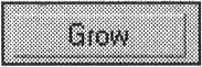
It is a good idea to also assign key combinations to the Grow and Shrink commands, for example, <Ctrl>+<=> and <Ctrl>+<->.
We must now chamfer some edges, namely, those on the top of the module and those on the bottom circle.
-
Select all edges on the top part and use 0.02 meter for the Chamfer Edges command (Fig. 3.5, a).
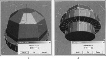
Figure 3.5: Chamfering -
Select one edge on the circle, press the Loop and Ring buttons on the control panel, and apply the Chamfer Edges command (Fig. 3.5, b).
The next step is to assign smoothing groups to the polygons. In our case, it is possible to do this automatically:
-
Select all polygons.
-
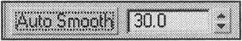
Apply the Auto Smooth command.
-
Control panel à Polygon Properties à Smoothing Groups à Auto Smooth
-
Choose a value that gives a good result. The value is simply a specification of the maximal angle (in degrees) between two polygons to which smoothing will be applied.
Now make the portholes and hatch. They can be created separately, but we recommend that you train yourself in "batch" modeling.
-
Select the polygons that will have portholes (shown with white arrows) and apply the Inset command (Fig. 3.6, a).
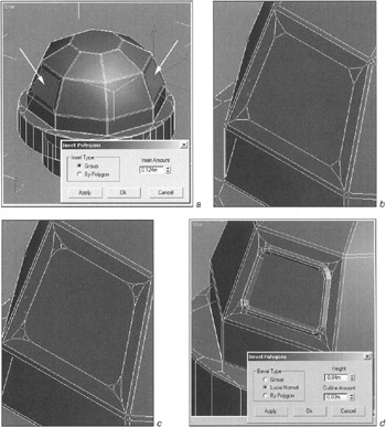
Figure 3.6: Sequence of creating the porthole -
Select the vertices of the polygons that will contain the portholes using the Convert to Vertex command. Make the chamfers (Fig. 3.6, b):
-
Context menu à Convert to Vertex
-
Context menu à Chamfer
-
-
Leave only the required subset of vertices selected using the Shrink command. Use the Chamfer command again, ensuring that the vertices do not merge (Fig. 3.6, c).
-
Extrude and Bevel the polygons (Fig. 3.6, d).
Note During your work, the geometry may start to "break." If that happens, use the Undo command to return to camfering the vertices and use the Retriangulate command on the selected porthole polygons. 3ds max has difficulties with multangular polygons, and the Retriangulate command helps improve the situation.
Be very careful with the Bevel and Inset commands. When a polygon is reduced in size, 3ds max does not keep track of its intersections with other polygons. (We encountered such a situation when modeling the glass of the portholes.) Even a small distortion between polygons leads to problems during rendering as a result of incorrect smoothing. The solution is to select the pair of vertices and apply the Collapse command.
-
Check the smoothing groups as described earlier.
-
Make the hatch a little differenly.
-
Go to a "direct" projection (e.g., Left view).
-
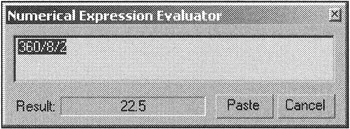
Rotate the lunar module around the vertical axis so that you directly face one of the facets (Fig. 3.7, a).
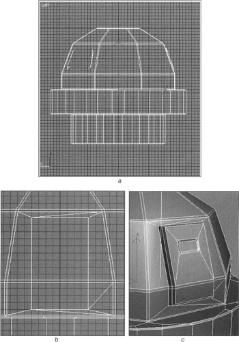
Figure 3.7: Sequence of modeling the hatchTip You can calculate the precise angle by dividing 360 by 8 and then by 2 with the integrated calculator. Press <Ctrl>+<N> in the window specifying the angle to turn the Z axis in the coordinate entry panel. You may want to use the Y axis when working with the Rear view, but the coordinate entry panel can interpret values as either absolute or relative. In the first case, all transformations take place in the world coordinates system; in the second case — with current coordinates. The mode is selected with the Absolute/Offset Mode Transform Type-In Toggle of the coordinate entry panel.
-
Display the grid (<G> key) and activate snaps to the grid (<S> key).
-
Check the Ignore Backfacing flag.
-
Cut the polygons as shown in Fig. 3.7, b. Don't worry about the unnecessary edges, as they will not impede your work:
-
Control panel à Edit Geometry à Cut
Tip Try to make the hatch yourself. You might want to use the Insert Vertex command instead Cut. (Our hatch was made in this way.) You will have to remove unnecessary edges and add others. Don't spend too much time on the process. Try to make the polygons with no more than four angles. You can find our result (Fig. 3.7, c) on the CD-ROM in \Lessons\Lesson 03\lesson 03-living_module.max.
-
|
| < Day Day Up > |
|
EAN: N/A
Pages: 136
- ERP System Acquisition: A Process Model and Results From an Austrian Survey
- The Effects of an Enterprise Resource Planning System (ERP) Implementation on Job Characteristics – A Study using the Hackman and Oldham Job Characteristics Model
- Context Management of ERP Processes in Virtual Communities
- A Hybrid Clustering Technique to Improve Patient Data Quality
- Development of Interactive Web Sites to Enhance Police/Community Relations