Enterprise Data Processing with the Data Flow
The Data Flow is the core data processing factory of Integration Services packages, where the primary data is handled, managed, transformed, integrated, and cleansed. Think of the Data Flow as a pipeline for data. A house, for example, has a primary water source, which is branched to all the different outlets in the house. If a faucet is turned on, water will flow out the faucet, while at the same time water is coming in from the source. If all the water outlets in a house are turned off, then the pressure backs up to the source to where it will no longer flow into the house until the pressure is relieved. On the contrary, if all the water outlets in the house are opened at once, then the source pressure may not be able to keep up with the flow of water and the pressure coming out of the faucets will be weaker. Of course, don't try this at home; it may produce other problems!
The Data Flow is appropriately named because the data equates to the water in the plumbing analogy. The data flows from the data sources through the transformations to the data destinations. In addition to the flowing concept, there are similarities to the data flow pressure within the pipeline. For example, while a data source may be able to stream 10,000 rows per second, if a downstream transformation consumes too much server resources, it could apply back pressure on the source and reduce the number of rows coming from the source. Essentially, this creates a bottleneck that may need to be addressed to optimize the flow. In order to understand and apply design principles in a Data Flow, an in-depth discussion of the Data Flow architecture is merited. Understanding several Data Flow concepts will give you a fuller perspective of what is going on under the hood of an executing package. Each of these will be addressed over the next few pages:
-
Data buffer architecture
-
Transformation types
-
Transformation communication
-
Execution trees
After your review of the architecture, your analysis will shift to monitoring packages in order to determine how the Data Flow engine is handling data processing.
Memory Buffer Architecture
The Data Flow manages data in groups of data called buffers. A buffer is merely memory that is allocated for the use of storing rows and columns of data where transformations are applied. This means that as data is being extracted from sources into the engine, it is put into these pre-allocated memory buffers. Buffers are dynamically sized based on row width (the cumulative number of bytes in a row) and other package and server criteria. A buffer, for example, may include 9000 rows of data with a few columns of data. Figure 10-5 shows a few groupings of buffers.
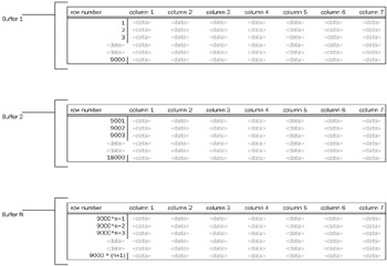
Figure 10-5
Although it is easy to picture data being passed down from transformation to transformation in the Data Flow similar to the flow of water in the pipeline analogy, this is not a complete picture of what is going on behind the scenes. Instead of data being passed down through the transformations, groups of transformations pass over the buffers of data and make in-place changes as defined by the transformations. Think of how much more efficient this process is than if the data were copied from one buffer to the next every time a transformation specified a change in the data! To be sure, there are times when the buffers are copied and other times when the buffers are held up in cache by transformations. The understanding of how and when this happens will help determine the right design to optimize your solution.
The understanding of how memory buffers are managed requires knowing something about the different types of Data Flow components — transformations and adapters.
Types of Transformations
The adapters and the transformations in the Data Flow have certain characteristics that group each into different categories. The base-level differences between them are the way they communicate with each other and how and when data is handed off from one transformation to another. Evaluating transformations on two fronts will provide the background you need to understand how the buffers are managed.
-
Blocking nature — streaming, blocking, and semi-blocking
-
Communication mechanism — synchronous and asynchronous
In reality, these classifications are related, but from a practical standpoint, discussing them separately provides some context to data management in the Data Flow.
Non-Blocking, Semi-Blocking, and Blocking
The most obvious distinction between transformations is their blocking nature. All transformations fall into one of three categories: non-blocking, semi-blocking, or blocking. These terms describe whether data in a transformation is passed downstream in the pipeline immediately, in increments, or after all the data is fully received.
Non-Blocking Transformations, Streaming and Row-Based
Most of the Integration Services Transformations are non-blocking. This means that the transformation logic that is applied in the transformation does not impede the data from moving on to the next transformation after the transformation logic is applied to the row. Two categories of non-blocking transformations exist, streaming and row-based. The difference is whether the Integration Services engine can use internal information and processes to handle the transformations or whether the engine has to call an external process to retrieve information used for the transformation. Some transformations can be categorized as streaming or row-based depending on their configuration, and these have been indicated below.
Streaming transformations are able to apply transformation logic quickly, using pre-cached data and processing calculations within the engine. In these transformations, it is rarely the case that a transformation will slip behind the rate of the data being fed to it. Therefore, they are classified as streaming. The following transformations stream the data from transformation to transformation in the data flow:
-
Audit
-
Character Map
-
Conditional Split
-
Copy Column
-
Data Conversion
-
Derived Column
-
Lookup (with a full cache setting)
-
Multicast
-
Percent Sampling
-
Row Count
-
Script Component (provided the script doesn't interact with a component outside the engine)
-
Union All (can also be categorized as semi-blocking)
The second grouping of non-blocking transformation is identified as row-based. These transformations are still non-blocking in the sense that the data can flow immediately to the next transformation after the transformation logic is applied to the buffer. The row-based description indicates that the rows flowing through the transformation are acted on one-by-one with a requirement to interact with an outside process such as a database, file, or component. Given their row-based processes, in most cases these transformations may not be able to keep up with the rate at which the data is fed to them, and the buffers are held up until each row is processed. The following transformations are classified as row-based:
-
Export Column
-
Import Column
-
Lookup (with a no cache or partial cache setting)
-
OLE DB Command
-
Script Component (where the script interacts with an external component)
-
Slowly Changing Dimension (each row is looked up against the dimension in the database)
Figure 10-6 shows a Data Flow composed of only streaming transformations. If you look at the row counts in the design UI, you will notice that the transformations are processing the data nearly at the same time because the row counts are very close in range.
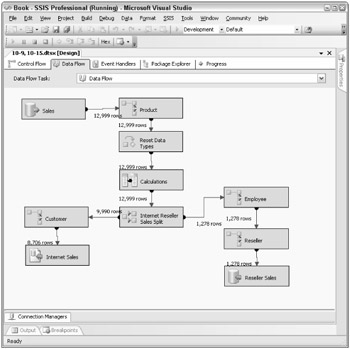
Figure 10-6
Also, notice in Figure 10-6 that data is still coming in from the source, but already records are being inserted into the destination. This very simple Data Flow is handling a high volume of data with minimal resources, such as memory usage, because of the streaming nature of the transformations components used.
Semi-Blocking Transformations
The next category of transformation components are the ones that hold up records in the Data Flow for a period of time before allowing the memory buffers to be passed downstream. These are typically called semi-blocking transformations, given their nature. Only a few out-of-the-box transformations are semi-blocking in nature:
-
Data Mining Query
-
Merge
-
Merge Join
-
Pivot
-
Term Lookup
-
Unpivot
-
Union All (also included in the streaming transformations list, but given a limited number of threads, the Union All will be semi-blocking in nature)
The Merge and Merge Join transformations are described in detail in Chapter 4. But in relation to the semi-blocking nature of these components, note that they require the sources to be sorted on the matching keys of the merge. Both of these transformations function by waiting for key matches from both sides of the merge (or join), and when the matching sorted keys from both sides pass through the transformations, the records can then be sent downstream while the next set of keys is handled. Figure 10-7 shows how a merge join within a data flow will partially hold up the processing of the rows until the matches are made.
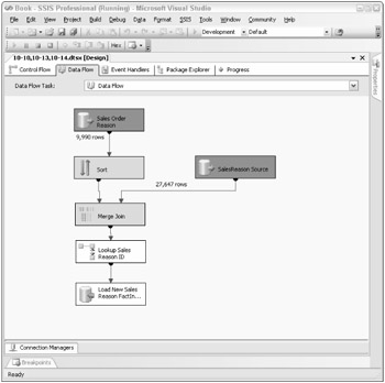
Figure 10-7
Typically the row count upstream of the Merge Join is much higher than the row count just below the Merge Join because the Merge Join waits for the sorted key matches as they flow in from both sides of the merge. Buffers are being released downstream, just not in a streaming fashion as in the non-blocking transformation components. You may also be wondering why there is not a Sort transformation on the right-side source of the Merge Join despite the fact that the transformations require the sources to be sorted. Stay tuned; the next chapter will cover one optimization technique, which is to sort the sources and tell the Data Flow that these sources are already sorted.
| Note | Semi-blocking transformations require a little more server resources since the buffers will need to stay in memory until the right data is received. |
Blocking Transformations
The final category of the blocking nature is the actual blocking transformations. For one reason or another, these components require the full connected upstream data set before releasing any row downstream to the connected transformations and destinations. The list is also smaller than the list of non-blocking transformations because of the limited logic applications that require all the rows. Here is the list of the blocking transformations:
-
Aggregate
-
Fuzzy Grouping
-
Fuzzy Lookup
-
Row Sampling
-
Sort
-
Term Extraction
The two widely used examples of the blocking transformations are the Sort and Aggregate transforms; each of these requires the entire data set before handing off the data to the next transform. For example, in order to have an accurate average, all the records need to be held up by the Aggregate transform. Similarly, to sort data in a flow, all the data needs to be available to the Sort transformation before the component will know the order in which to release records downstream. Figure 10-8 shows a Data Flow that contains an Aggregate transformation. The screen capture of this process shows that the entire source has already been brought into the data flow, but no rows have been released downstream while the transformation is determining the order.
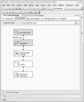
Figure 10-8
With a blocking component in the Data Flow, as you can see in Figure 10-8, the data is no longer streaming through the Data Flow, and there will not be a time when data can be inserted into the destination while data is being extracted from the source.
| Note | Blocking transformations are more resource-intensive for several reasons. First, since all the data is being held up, either the server must use a lot of memory to store the data or, in the case where the server does not have enough memory, a process of file staging happens, which requires the IO overhead of landing the data to disk temporarily. The second reason these transformations are intensive is that they usually put a heavy burden on the processor to perform the work of data aggregation, sorting, or fuzzy matching. |
Synchronous and Asynchronous Transformation Outputs
Another important differentiation between transformations is how transformations that are connected to one another by a path communicate with one another. While closely related to the discussion on the blocking nature of transformations, synchronous and asynchronous refer more to the relationship between the input and output component connections.
Some transformations have an Advanced Editor window, which, among other things, drills into specific column-level properties of the transformations' input and output columns and is useful in explaining the difference between synchronous and asynchronous outputs. Figure 10-9 shows the Advanced Editor of the Sort transformation, highlighting the Input and Output Properties tab. This particular transformation has a Sort Input and Sort Output group with a set of columns associated with each.
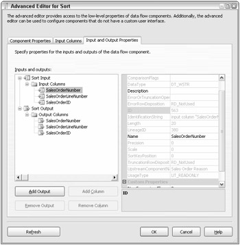
Figure 10-9
When a column is highlighted, the advanced properties of that column are displayed on the right, as Figure 10-9 shows. The advanced properties include such things as the data type of the column, the description, and so on. One important property to note is the LineageID. This is the integer pointer to the column within the buffers. Every column used in the Data Flow has at least one LineageID in the Data Flow. A column can have more than one Lineage ID as it passes through the Data Flow based on the types of transformation outputs (synchronous or asynchronous) that a column goes through in the Data Flow.
Asynchronous Transformation Outputs
You will begin with the asynchronous definition because it will be easier to explain first, and then you will come back to synchronous outputs for a comparison. A transformation output is asynchronous if the buffers used in the input are different from the buffers used in the output. In other words, many of the transformations cannot perform the given operation and at the same time preserve the buffers (the number of rows or the order of the rows), so a copy of the data must be made to accomplish the desired effect.
The Aggregate transformation, for example, may output only a fraction of the number of rows coming into it, or when the Merge Join transformation has to marry two data sets together, the resulting number of rows will not be equivalent to the number of input rows. In both cases, the buffers are received, the processing is handled, and new buffers are created.
The Advanced Editor of the Sort shown in Figure 10-9 highlights an input column. One of the properties of the input column is the LineageID. Notice that in this transformation, all the input columns are duplicated in the output columns list. In fact, as Figure 10-10 shows, the output column highlighted for the same input has a different LineageID.
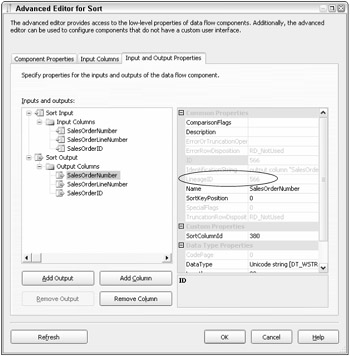
Figure 10-10
The LineageIDs are different for the same column because the Sort transformation output is asynchronous and the data buffers in the input are not the same buffers in the output; therefore a new column identifier is needed for the output. In the preceding examples, the input LineageID is 380 while the output column LineageID is 566.
A list doesn't need to be included here, because all of the semi-blocking and blocking transformations already listed have asynchronous outputs by definition — none of them can pass input buffers on downstream because the data is held up for processing and reorganized.
| Note | One of the Integration Services engine components is called the buffer manager. For asynchronous component outputs, the buffer manager is busy at work, decommissioning buffers for use elsewhere (in sources or other asynchronous outputs) and reassigning new buffers to the data coming out of the transformation. |
Synchronous Transformation Outputs
A synchronous transformation is one where the buffers are immediately handed off to the next downstream transformation at the completion of the transformation logic. This may sound like the definition given for streaming transformations, and it should, since there is almost complete overlap between streaming transformations and synchronous transformations. The word buffers was intentionally used in the definition, because the important point is that the same buffers received by the transformation input are passed out the output. Regarding the LineageIDs of the columns, they remain the same as the data is passed through the synchronous output, without a need to duplicate the buffers and assign a new LineageID as discussed previously in the asynchronous transformation output section.
Figure 10-11 shows the Advanced Editor of a synchronous component output, the Derived Column transformation. There is a big difference between the advanced Input and Output properties of the Derived Column compared with the Sort (shown in Figure 10-9 and Figure 10-10). As you saw, all of the columns in the Sort's input and output are duplicated, while Figure 10-11 shows that the Derived Column transformation contains only output columns.
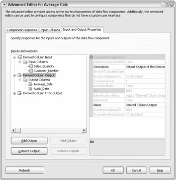
Figure 10-11
The rest of the columns are not included in the input or output list because they are not directly used by the transformation and because the Derived Column transformation output is synchronous. In other words, the columns coming from the upstream component flow through the Derived Column transformation (in this example) and are available to the next downstream component.
| Note | A transformation is not limited to a single synchronous output. Both the Multicast and the Conditional Split can have multiple outputs, but all the outputs are synchronous. |
With the exception of the Union All, all of the non-blocking transformations listed in the previous section also have synchronous outputs. The Union All, while it functions like a streaming transformation, is really an asynchronous transformation. Given the complexity of unioning multiple sources together and keeping track of all the pointers to the right data from the different source inputs, the Union All instead copies the buffers as it receives them and passes them off to the downstream transformations.
| Note | Synchronous transformation outputs preserve the sort order of incoming data, while some of the asynchronous transformations do not. The Sort, Merge, and Merge Join asynchronous components of course have sorted outputs because of their nature, but the Union All, for example, does not. |
A definitive way to identify synchronous versus asynchronous components is to look at the SynchronousInputID property of the Column Output properties. If this value is 0, the component output is asynchronous, but if this property is set to a value greater than 0, the transformation output is synchronous to the input whose ID matches the SynchronousInputID value. Figure 10-11 shows the Derived Column transformation with a value of 1064, indicating that the Derived Column transformation output is synchronous and tied to the single Derived Column input.
Source and Destination Adapters
You should also briefly look at adapters in this section, since they are integral to the Data Flow. Because of their differences in functionality, sources and destinations are therefore classified differently.
In looking at the advanced properties of a source adapter, the source will have the same list of input columns and output columns. The external columns come directly from the source and are copied into the Data Flow buffers and subsequently assigned LineageIDs. While the external source columns do not have LineageIDs, the process is effectively the same as an asynchronous component output. Source adapters require buffers to be allocated where the incoming data can be grouped and managed for the downstream transformations to perform work against.
Destination adapters, on the other hand, function as synchronous components, since their buffers are de-allocated and data is loaded into the destinations. In the advanced properties of the destination adapter (as shown in Figure 10-12), an External Column list is also shown, which represents the destination columns used in the load. Notice that there is no primary Output container (besides the Error Output) for the destination adapter since the buffers do not flow through the component but rather are committed to a destination adapter as a final step in the Data Flow.
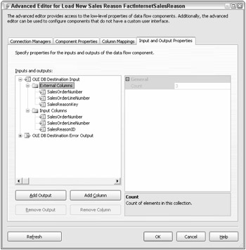
Figure 10-12
Advanced Data Flow Execution Concepts
You have already looked at several advanced Integration Services engine concepts that apply to transformations within the Data Flow. This section will take and apply the discussion of synchronous and asynchronous transformations and tie them together to provide the bigger picture of a package execution.
Relevant to this discussion is a more detailed understanding of buffer management within an executing package based on how the package is designed.
Execution Trees
In one sense, you have already looked at execution trees, although they weren't explicitly referred to by this name. An execution tree is the logical grouping of Data Flow components (transformations and adapters) based on their synchronous relationship to one another. Groupings are delineated by asynchronous component outputs that indicate the completion of one execution tree and the start of the next.
Figure 10-13 shows a moderately complex Data Flow that uses multiple components with asynchronous outputs.
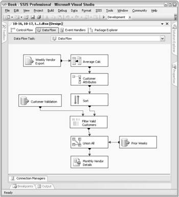
Figure 10-13
You will recall that components with asynchronous outputs use different input buffers. The input participates in the upstream execution tree, while the asynchronous output begins the next execution tree. In light of this, the execution trees for Figure 10-13 start at the source adapters and are then completed, and a new execution tree begins at every asynchronous transformation. The example in Figure 10-14 has six execution trees.
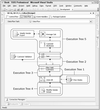
Figure 10-14
Execution trees are base 0, meaning you count them starting with a 0. In the next section, you will see how the pipeline logging identifies them. Although the execution trees seem out of order, you have used the explicit order given by the pipeline logging.
In the next section, you will address ways to log and track the execution trees within a Data Flow, but for now the discussion will emphasize the particulars of what happens in an execution tree.
| Important | Execution Trees Principle #1: Each component within an execution tree applies work (transformation logic) on the same set of buffers as the rest of the synchronous components in the same execution tree. |
As previously explained, the input and output buffers in a transformation with asynchronous outputs are different because the buffer data grouping cannot be preserved in both count and order. Rows within the input buffers may merge with other buffers, creating more (or fewer) rows in the output buffers than in either of the source buffers. Or input buffers may contain data that needs to be sorted or aggregated, which also fails to preserve the order or row count.
This means that when Integration Services executes a package, the buffer manager defines different buffer profiles based on the execution trees within a package. All the buffers used for a particular execution tree are identical in definition. When defining the buffer profile for each execution tree, the Integration Services buffer manager looks at all the transformations used in the execution tree and includes every column in the buffer that is needed at any point within the execution tree. If you focus on execution tree #1 in Figure 10-15, you'll see that it contains a source adapter, a Derived Column transformation, and a Lookup. Without looking at the source properties, the following list defines the four columns that the source adapter is using from the source:
-
CurrencyCode
-
CurrencyRate
-
AverageRate
-
EndofDayRate
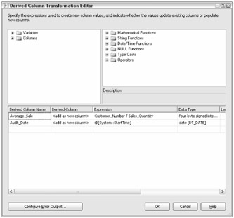
Figure 10-15
A quick look at the Derived Column transformation in Figure 10-15 shows that two more columns are being added to the Data Flow: Average_Sale and Audit_Date.
And finally, the Lookup transformation adds another three columns to the Data Flow, as Figure 10-16 highlights.
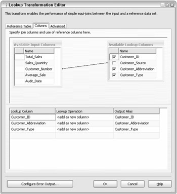
Figure 10-16
Added together, the columns used in these three components total nine. This means that the buffers used in this execution tree will have nine columns allocated, even though some of the columns are not used in the initial transformations or adapter. Optimization of a Data Flow can be compared with optimizing a relational table, where the smaller the width and number of columns, the more that can fit into a Data Flow buffer. This has some performance implications, and the next chapter will look in more detail at optimizing buffers.
| Important | Execution Trees Principle #2: Different execution trees use a different set of buffers, and therefore data in a new execution tree requires the transformed data to be copied into the new buffers allocated for the next in-line execution tree. |
When a buffer is used in an execution tree and reaches the transformation input of the asynchronous component (the last step in the execution tree), the data is subsequently not needed since it has been passed off to a new execution tree and new set of buffers. At this point, the buffer manager can use the allocated buffer for other purposes in the Data Flow.
| Important | Execution Trees Principle #3: Integration Services uses one process thread for each execution tree and one process thread for each source adapter. |
The final important point about execution trees involves situations where the Integration Services engine can multi-thread processes for parallelization. No matter how many synchronous transformations are used in an execution tree, the engine can use only one process thread per execution tree and one process thread per source adapter. Consequently, processing can be an Integration Services bottleneck if the execution threads have a large number of synchronous processes or if there are more execution trees than available system threads. In the first case, when a Data Flow uses many synchronous transformations that require intensive processes, such as the Lookup transformation, a single execution thread may have difficulty keeping up with the amount of work required. In the latter case, when there are many execution trees with a limited number of available threads, some of the downstream execution trees may have to wait for threads to be freed up in order to run their processes.
One advanced property of the Data Flow is the EngineThreads property. In the Control Flow, when a Data Flow task is highlighted, this property appears in the property window list, as Figure 10-17 shows.
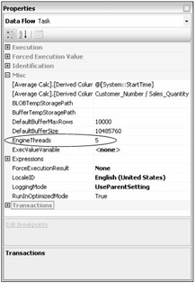
Figure 10-17
The EngineThreads property is the maximum number of threads available to the Data Flow in question. If there are multiple Data Flows in the package, each retains a separate EngineThreads setting and should be balanced between the Data Flows. In the last section of this chapter, you will look at the number of threads used in a Data Flow. The value for EngineThreads does not include the threads allocated for the number of sources in a Data Flow, which are allocated separate threads.
Monitoring Data Flow Execution
Built into the Integration Services logging is the ability to monitor specific pipeline events related to execution trees. This can be very useful in understanding your Data Flow and how the engine is managing buffers and execution.
Pipeline logging events are available in the Logging features of Integration Services. An overview of the general Integration Services logging is provided in Chapter 13, but for this discussion, you will focus on only the specific pipeline events that relate to the execution tree discussion. Two specific pipeline execution events are available to capture during the processing:
-
PipelineExecutionPlan
-
PipelineExecutionTrees
To capture the event, create a new log entry through the logging designer window under the SSIS menu Logging option. The pipeline events are available only when your Data Flow is selected in the tree menu navigator of the package executable navigator, as Figure 10-18 shows.
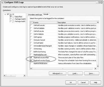
Figure 10-18
On the Details tab of the Configure SSIS Logs window, shown in Figure 10-18, the two execution information log events listed above are available to capture. When the package is run, these events can be tracked to the selected log provider as defined. However, during development, it is useful to see these events when testing and designing a package. Integration Services includes a way to see these events in the Business Intelligence Development Studio as a separate window. The Log Events window can be pulled up either from the SSIS menu by selecting "Log Events" or through the View menu, listed under the Other Windows submenu. As is standard, this window can float or be docked in the designer.
When the package is executed in design-time through the interface, the log events selected will be displayed in the Log Events window. For each Data Flow, there will be one event returned for the PipelineExecutionPlan event and one for the PipelineExecutionTrees event, as shown in Figure 10-19. These log details have been captured from the sample Data Flow used in Figure 10-13 and Figure 10-14.

Figure 10-19
Note that all pipeline events selected in the Logging configuration are included in the Log window. To capture the details for a more readable view of the Message column, simply right-click on the log entry and copy, which will put the event message into the clipboard. A more detailed analysis of the message text is discussed in the following section.
Pipeline Execution Tree Log Details
The execution tree log event describes the grouping of transformation inputs and outputs that participate in each execution tree. Each execution tree is numbered for readability. The following text comes from the message column of the PipelineExecutionTrees log entry.
begin execution tree 0 output "OLE DB Source Output" (582) input "Merge Join Right Input" (686) end execution tree 0 begin execution tree 1 output "OLE DB Source Output" (749) input "Union All Input 2" (976) end execution tree 1 begin execution tree 5 output "Flat File Source Output" (878) input "Derived Column Input" (1064) output "Derived Column Output" (1065) input "Lookup Input" (276) output "Lookup Output" (280) input "Sort Input" (553) end execution tree 5 begin execution tree 2 output "Sort Output" (554) input "Merge Join Left Input" (685) end execution tree 2 begin execution tree 3 output "Merge Join Output" (687) input "Union All Input 3" (1042) end execution tree 3 begin execution tree 4 output "Union All Output 1" (965) input "SQL Server Destination Input" (813) end execution tree 4
In the log output, each execution tree evaluated by the engine is listed with a begin and an end, with the transformation input and outputs that participate in the execution tree. Some execution trees may have several synchronous component outputs participating in the grouping, while others may be composed of only an input and output between two asynchronous components. The listing of the execution trees is base 0, so the total number of execution trees for your Data Flow will be the numeral of the last execution tree plus one. In this example, there are six execution trees (note that execution tree 5 is listed higher in the output code).
A quick way to identify synchronous and asynchronous transformation outputs in your data flow is to review this log. Any transformation where both the inputs and outputs are contained within one execution tree is synchronous. Contrarily, any transformation where one or more inputs are separated from the outputs in different execution trees therefore has asynchronous outputs.
Pipeline Execution Plan Log Details
The second type of log detail that applies to the discussion of execution trees and execution threads is the PipelineExecutionPlan. This particular log detail dives one step deeper into the Integration Services engine process for a Data Flow by identifying the threads that will be allocated and used during the process. The following text comes from the message column of the PipelineExecutionPlan log output.
SourceThread0 Drives: 573 Influences: 684 800 963 Output Work List CreatePrimeBuffer of type 1 for output ID 582. SetBufferListener: "WorkThread0" for input ID 686 CallPrimeOutput on component "Customer Validation" (573) End Output Work List End SourceThread0 SourceThread1 Drives: 740 Influences: 800 963 Output Work List CreatePrimeBuffer of type 4 for output ID 749. SetBufferListener: "WorkThread1" for input ID 976 CallPrimeOutput on component "Prior Weeks" (740) End Output Work List End SourceThread1 SourceThread2 Drives: 877 Influences: 266 552 684 800 963 1063 Output Work List CreatePrimeBuffer of type 11 for output ID 878. SetBufferListener: "WorkThread2" for input ID 1064 CallPrimeOutput on component "Weekly Vendor Export" (877) End Output Work List End SourceThread2 WorkThread0 Drives: 684 Influences: 684 800 963 Input Work list, input ID 685 (1 EORs Expected) CallProcessInput on input ID 685 on component "Filter Valid Customers" (684) for view type 8 End Input Work list for input 685 Input Work list, input ID 686 (1 EORs Expected) CallProcessInput on input ID 686 on component "Filter Valid Customers" (684) for view type 2 End Input Work list for input 686 Output Work List CreatePrimeBuffer of type 7 for output ID 687. SetBufferListener: "WorkThread1" for input ID 1042 CallPrimeOutput on component "Filter Valid Customers" (684) End Output Work List End WorkThread0 WorkThread1 Drives: 963 Influences: 800 963 Input Work list, input ID 976 (1 EORs Expected) CallProcessInput on input ID 976 on component "Union All" (963) for view type 5 End Input Work list for input 976 Input Work list, input ID 1042 (1 EORs Expected) CallProcessInput on input ID 1042 on component "Union All" (963) for view type 9 End Input Work list for input 1042 Output Work List CreatePrimeBuffer of type 7 for output ID 965. SetBufferListener: "WorkThread3" for input ID 813 CallPrimeOutput on component "Union All" (963) End Output Work List End WorkThread1 WorkThread2 Drives: 1063 Influences: 266 552 684 800 963 1063 Input Work list, input ID 1064 (1 EORs Expected) CallProcessInput on input ID 1064 on component "Average Calc" (1063) for view type 14 ActivateVirtualBuffer index 1 CallProcessInput on input ID 276 on component "Customer Attributes" (266) for view type 12 ActivateVirtualBuffer index 2 CallProcessInput on input ID 553 on component "Sort" (552) for view type 13 End Input Work list for input 1064 Output Work List CreatePrimeBuffer of type 7 for output ID 554. SetBufferListener: "WorkThread0" for input ID 685 CallPrimeOutput on component "Sort" (552) End Output Work List End WorkThread2 WorkThread3 Drives: 800 Influences: 800 Input Work list, input ID 813 (1 EORs Expected) CallProcessInput on input ID 813 on component "Monthly Vendor Details" (800) for view type 10 End Input Work list for input 813 Output Work List End Output Work List End WorkThread3 7/31/2005 11:23:56 PM 7/31/2005 11:23:56 PM
This text is a little more difficult to decipher. A few pointers will help determine some details of the pipeline execution plan. First of all, execution threads are identified by two types, SourceThread and WorkThread. As may be apparent, the SourceThreads are allocated for each of the source adapters. In the discussion of execution threads, recall that the number of possible threads used in a Data Flow is the number of sources plus the number of execution trees. Therefore, in this example, the number of SourceThreads is three and each is numbered (the SourceThread count is base 0, so the third thread is identified as SourceThread2).
The WorkThread is the second type of thread, which applies to the Data Flow execution trees. It is important to note that the WorkThreads are directly related to the EngineThread property. If the number of execution trees in a Data Flow exceeds the number of EngineThreads available, then a WorkThread may be assigned to more than one execution tree. Although there is not an explicit map between an execution tree and a WorkThread in the PipelineExecutionPlan output, the mapping can be inferred by looking at the CallProcessInput property, which shows the transformations assigned to the WorkThread.
By the using the two pipeline log entries just described, you can now better understand how the engine is processing your data. In any system, the road to applying design principles first requires a level of understanding.
EAN: 2147483647
Pages: 182