7.3 Load-splitting and load-sharing techniques
|
|
7.3 Load-splitting and load-sharing techniques
One of the ways you can scale up device performance is by spreading the traffic load between multiple devices. There are several ways to achieve this; the following list is not meant to be exhaustive:
-
DNS, ARP, NAT, HTTP, and FTP load balancers
-
IP load balancers (integrated OS features or specialized systems)
-
Generic load-sharing protocols such as the VRRP and HSRP
-
Policy-based routes
-
Port hashing techniques
The key to this problem is to split traffic and allow each device to deal with a fair proportion of the overall traffic. The first issue to address is whether to do this on a per-packet basis or on a flow basis. The per-packet mechanism (e.g., round robin) is likely to result in fairer resource allocation but is also more likely to result in problems with retransmissions (if end systems cannot resequence packets); it may also be harder to debug and generate accounting data. If the load is to be spread among firewalls, state synchronization may rely on flows being handled deterministically (the flow, or session, goes in via one interface and returns back through that interface rather than sessions being asymmetrical).
7.3.1 An introduction to server load-sharing algorithms
Load-sharing server clusters, fronted by a proxy server, are a common technique used on internetworks, since they offer both resilience and scalable performance. Server clusters can be application specific (a DNS load sharer) or generic IP application servers. There are a number of algorithms available to iterate new sessions fairly between servers in a group. Load can be distributed nonintelligently or intelligently, based on cost, delay, server status, and other factors. It is useful to consider two environments for server load sharing: the case where the proxy server is local to the servers and the case where the proxy server is remotely located, as follows:
-
Local proxy server algorithms assume that all server pool members are at equal or nearly equal proximity to the proxy server; hence the load distribution can be based solely on either resource availability or system load on remote servers. Network costs are irrelevant in this scenario.
-
Remote proxy server algorithms assume that all server pool members have equal resource availability, and the criterion for selection would be proximity, or network cost, required to reach these servers.
The two topologies are illustrated in Figure 7.8. There are basically two approaches we can use to monitor session load on server pool members: nonintrusive and intrusive. Nonintrusive algorithms use simple heuristic techniques to distribute requests. Intrusive algorithms require protocol interaction between each member of the server group and the proxy server, so that real-time status information can be passed between them.
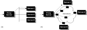
Figure 7.8: (a) Local proxy configuration. (b) Remote proxy configuration.
Local load-sharing algorithms
With local proxy servers the selected algorithm should ideally use precise knowledge of real-time resource availability and system load for each host in the server pool, so that selection of the host with maximum unutilized capacity would be the obvious choice. However, this is not so easy to achieve. Some common nonintrusive algorithms are as follows:
-
Round robin—A scheme where a server is selected from a list on a round-robin basis, without regard to load on the host. If a particular server is busy or down, this algorithm may take no notice unless additional interactive techniques are used.
-
Random—A scheme where a server is selected from a list at random, without regard to load on the host. If a particular server is busy or down, this algorithm may take no notice unless additional interactive techniques are used.
-
Domain—A scheme where a server is selected from a list regarding proximity to the client based on domain names, without regard to load on the host. If a particular server is busy or down, this algorithm may take no notice unless additional interactive techniques are used.
-
Least load first—This is an improvement over the round-robin approach in that the host with the least number of sessions bound to it is selected to service a new session. This approach is not without its drawbacks. Each session is assumed to be as resource consuming as any other session, independent of the type of service the session represents, and all hosts in the server pool are assumed to be equally resourceful.
-
Least traffic first—A further improvement over the previous algorithm is to measure system load by tracking packet counts or byte counts directed from or to each of the member hosts over a period of time. Although packet counts are not the same as system load, it is a reasonable approximation.
-
Least weighted load first—This would be an enhancement to the first two. This allows administrators to assign weights to sessions (based on likely resource consumption estimates of session types) and weights to hosts (based on resource availability). The sum of all session loads by weight assigned to a server, divided by weight of the server, would be evaluated to select the server with the least weighted load to assign for each new session. Say, FTP sessions are assigned 5 times the weight (5x) of a Telnet session (x), and server S3 is assumed to be 3 times as resourceful as server S1. Let us also say that S1 is assigned one FTP session and one Telnet session, whereas S3 is assigned two FTP sessions and five Telnet sessions. When a new Telnet session needs assignment, the weighted load on S3 is evaluated to be (2 × 5x + 5 × x)/3 = 5x, and the load on S1 is evaluated to be (1 × 5x + 1 × x) = 6x. Server S3 is selected to bind the new Telnet session, since the weighted load on S3 is smaller than that of S1.
Distributed load-sharing algorithms
When the proxy and server cluster, are geographically separated over large distances, the cost to reach them could vary markedly. In this case the load algorithm could use cost information to select servers based on proximity to the client. The algorithm would need to access routing tables for metric and reachability data from protocols such as OSPF to build a true cost of accessing a server in the group. The following algorithms are nonintrusive:
-
Weighted least load first algorithm—The selection criteria would be based on cost of access to server and the number of sessions assigned to server. The product of cost and session load for each server would be evaluated to select the server with the least weighted load for each new session. Assume the cost of accessing server S1 is twice as much as that of server S2. In that case, S1 will be assigned twice as much load as that of S2 during the distribution process. When a server is not accessible due to network failure, the cost of access is set to infinity and no further load can be assigned to that server.
-
Weighted least traffic first algorithm—An improvement over the previous algorithm would be to measure network load by tracking packet count or byte count directed from or to each of the member hosts over a period of time. Although packet count is not the same as system load, it is a reasonable approximation. So, the product of cost and traffic load (over a fixed duration) for each server would be evaluated to select the server with the least weighted traffic load for each new session.
Intrusive load-sharing algorithms
All of the previous algorithms determine the capacity of servers using heuristic techniques. In practice it is necessary to use closely coupled techniques for accurate remote prediction and status monitoring of system capacity. This class of algorithm is called intrusive, since work is required on the part of the host system. Intrusive algorithms fall into the following broad categories:
-
Round-trip time—A scheme where a server is selected from a list based on knowledge acquired using ping to periodically determine round-trip times between the proxy and each of the destination servers. The server with the shortest round-trip time should be selected. This algorithm has no regard for true load on the host, but clearly the lack of response indicates that the server in unavailable or very slow (ping is not a reliable method of testing server load, since higher-layer software and protocols are not exercised by ICMP). This method can be used in conjunction with heuristic techniques reasonably effectively.
-
Exercising content—Advanced load balancers can run scripts to trigger real application interaction to test the true response time of servers for specific applications. For example, a simple HTTP session could be periodically activated to test Web server response time. Clearly, this places some additional background load on the server but still remains transparent. This is a very granular way of measuring performance on servers running multiple services concurrently, since services such as FTP and HTTP can all be explicitly measured with reasonable accuracy.
-
Agent-based monitoring—Remote agent software can be deployed on each server node. This interacts with monitoring software on the proxy server, providing detailed status reports concerning resource availability. The remote agent software needs to be run in the background so it does not consume excessive resources on the server. Communications between the agent and monitor may be via either standard or proprietary protocols (e.g., SNMP or RMON). Typically this software is configurable, to allow the network administrator to tune features such as the update/measurement interval according to local conditions.
Although active algorithms are a little more complex to implement and deploy, they offer a more optimal solution for accurate load distribution, at the price of sacrificing additional resource on the server pool.
Dead host detection
One of the problems with server clusters is detecting host availability and dynamically adjusting for this as part of the normal load-sharing operations. In a naive implementation, where this functionality is not included, client sessions could be directed to unreachable host addresses (e.g., where the server is down). Many heuristic approaches are available, including the following:
-
Sending pings periodically to each server in the cluster would be one way to determine availability.
-
Another approach would be to track traffic originating from a host in the group when it is assigned new sessions. If no activity is detected in a few seconds, that server should be declared dead and taken out of service temporarily until further activity is detected (or the proxy explicitly tests the server status).
Note that although ping is commonly used, it is potentially misleading if used to assess response times, since a host may turn around pings very quickly even if other resources on the system (such as disk IO) are overloaded.
TCP and UDP session use
By convention TCP/IP servers use TCP and UDP ports 0 to 1,023 to listen for incoming connections. Clients typically select source ports in the range of 1,024 to 65,535. However, this convention is not always adhered to; some clients use source port numbers in the 0 to 1,023 range, and some applications listen on ports in the 1,024 to 65,535 range.
7.3.2 DNS load sharing
A DNS load balancer can be used to improve both performance and network reliability by offering a cluster of DNS servers to the network under a single host name. This system acts as a proxy server by intercepting name resolution requests for a particular service and then cycling through a table of alternate IP addresses distributing DNS requests to servers, based on their availability. This functionality only benefits users of DNS; it is not a general-purpose load-sharing system. DNS load balancers can be broadly divided into two groups, as follows:
-
Nonintelligent DNS load balancers distribute DNS requests in a round-robin manner without any knowledge of server status. This is not strictly a load-balancing method, since there is no real way of knowing what load the hosts are currently experiencing, and we are distributing traffic by session, not by packet (with a large number of sessions the traffic will be expected to average out but there is no guarantee). This mode is often called round-robin DNS. An example of this technology is Bind—the DNS implementation included with many UNIX implementations and available under Windows NT. Bind does not assess the current status of each DNS server, and so it may forward DNS requests to a server that is overloaded or out of service. For further information on Bind, see [22, 23].
-
Intelligent DNS load balancers improve functionality by being aware of the load and availability of each DNS server in a cluster. A small process runs on each server and reports back to the load balancer. This functionality is being increasingly embedded into highspeed switching and routing devices, and also being integrated into general-purpose load-sharing systems, switches, and firewalls. Examples include the ArrowPoint (now part of Cisco) range of content-aware switches, Metainfo's IP/Load Balancer, and Cisco's Local-Director.
The advantages of DNS proxies are that they are protocol transparent, simple to deploy, and offer improved performance and reliability. However, these advantages may be negated where name servers and Web browsers cache the IP address returned by the DNS server (commonly done for local performance advantages). These systems may also ignore the DNS Time-To-Live (TTL) value, defeating the possibility of dynamically adjusting load per session. When deploying DNS load balancers, careful attention should be paid to the design. A DNS load balancer may become a single point of failure. A load balancer advertises its name and address to other DNS servers on the Internet, which cache the information. If the load balancer dies, remote clients may not be able to reach any of the DNS server clusters behind it until the cache in their local DNS server expires. The default timeout for DNS entries in many UNIX implementations is five minutes (some servers may be configured to retain DNS information for more than 40 days). Since this functionality is increasingly being integrated into general-purpose load-sharing systems, switches, and firewalls, these devices can often be clustered to provide appropriate levels of fault tolerance. The interested reader is directed to [24–26] for further details about the operation of DNS. Reference [27] documents DNS support issues for load balancing.
7.3.3 HTTP load sharing
HTTP load sharing proxies (sometimes referred to as logical HTTP servers or HTTP redirectors) can be used as a method for distributing requests for Web services. This functionality is limited to Web traffic only. As with DNS, load balancing is implemented as a proxy service, and this has the advantage of being simple to implement and transparent. From the user's perspective there is only one Web server, whereas in reality there may be several servers, often located physically at different sites for additional resilience. Note that Web servers do not necessarily have to be on a particular interface on the proxy (e.g., if this functionality is implemented in a firewall, some Web servers may be behind the firewall, others may be accessible via the Internet).
In effect redirection means that the client browser effectively has two HTTP sessions (although the client is generally unaware of this). The client initially makes an HTTP request to the proxy. The proxy recognizes the destination URL as a logical server and selects the most appropriate server (based on its load-balancing algorithm). The proxy then notifies the client that the URL is being directed via the URL redirection feature of HTTP, redirecting the client to a specific IP address. In practice, this functionality can be negated if the user caches URLs locally as bookmarks, since the HTTP proxy will be bypassed. HTTP load sharing may be implemented in standalone devices or integrated into general-purpose load balancers, such as ArrowPoint's content-aware switches, Cisco's LocalDirector, and Checkpoint's Firewall-1.
7.3.4 FTP load sharing
FTP load-sharing proxies (sometimes referred to as logical FTP servers) can be used as a method for distributing requests for FTP services. This functionality is limited to FTP traffic only. As with HTTP, load sharing is implemented as a proxy service, and this has the advantage of being simple to implement and transparent. From the user's perspective there is only one FTP server, whereas in reality there may be several servers, often located physically at different sites for additional resilience. As with HTTP load sharing, FTP servers do not necessarily have to be on a particular interface on the proxy. However, in this case, unlike HTTP load sharing, there is no explicit redirection; all server sessions are handled through the proxy.
The client initially makes an FTP request to the proxy. The proxy recognizes the destination IP address or name as a logical server and selects the most appropriate server (based on its load-balancing algorithm). The proxy then performs network address translation on the session so that the client is unaware of the true destination server. Address translation is performed in both directions (so that even FTP back connections are handled properly). FTP load sharing may be implemented in standalone devices or integrated into general-purpose load balancers, such as ArrowPoint's content-aware switches, Cisco's LocalDirector, and Checkpoint's Firewall-1.
7.3.5 ARP load sharing
Proxy ARP can be used to provide resilient paths to services and spread load. For example, assume we have a client connected to a LAN-A. The client has an IP address 140.4.3.1 and a mask 255.255.0.0. There are two routers connected to LAN-A, and both remotely connect to LAN-B, which attaches to a server. The server uses IP address 140.4.2.1 and a mask 255.255.255.0. Both routers run proxy ARP. When the client wishes to connect to the server, it believes that the server is locally attached (since it uses a natural class B mask). It, therefore, ARPs locally. Both routers receive the ARP and will respond with their own MAC addresses. The client will cache the MAC address from the most recent ARP response and send the packet addressed to the server's IP address and one of the router's MAC addresses. The relevant router will forward the packet onto LAN-B. This approach is simple and transparent but does have some drawbacks. If one of the routers dies, then all client sessions using that router will eventually time out. Clients will then have to generate a new ARP request, which should be responded to by the working router. All further sessions will be directed to this single router. If the failed router recovers, it will not be used until sessions are broken or new clients come online. ARP timers are quite long, and it may take considerable time for the load to be evenly distributed between routers. For further information on basic ARP and Proxy ARP operations, the interested reader is referred to [28].
7.3.6 NAT load sharing
Network Address Translation (NAT) dynamically changes source and destination IP addresses (and possibly ports) as IP packets traverse the NAT system. NAT is typically employed for security applications or to convert private IP addresses to registered IP addresses (NAT operations are described in [29]). Since this is a critical function, NAT systems are often incorporated in firewalls or perimeter routers placed at strategic locations on the network. In a client/server environment, this gives a NAT system the opportunity to distribute sessions among different servers by dynamically changing the destination IP address to match one of several servers in a hunt group. For complete transparency, packets returned from the servers must traverse the NAT device so that addresses are flipped back to their original forms and forwarded to the client. Since NAT operates at the IP layer, it is not tied to a specific service.
An enhanced version of NAT called Load Share Network Address Translator (LSNAT) is described in [RFC2391]. LSNAT extends NAT to offer load sharing across a pool of servers, instead of directing requests to a single server. LSNAT uses real-time load-sharing algorithms to transparently distribute the load across a server group. This enables servers to scale in large internetwork environments. Unlike traditional NAT, LSNAT devices initiate translations on inbound sessions by binding each session represented by a tuple (client address, client TCP/UDP port, virtual server address, server TCP/UDP port) to one of the servers in the cluster, selection based on a real-time load-sharing algorithm. A virtual server address is a globally unique IP address that identifies a physical server or a group of servers that provide similar functionality. In essence, when a client sends a request to a server (using virtual address), the LSNAT system transparently redirects the request to one of the hosts in the server pool, chosen using a real-time load-sharing algorithm. Multiple sessions may be initiated from the same client, and each session could be directed to a different host based on load balancing across server pool hosts at the time. If load sharing is desired for just a few specific services, the configuration on LSNAT could be defined to restrict load sharing for just the services desired.
To check if a server is up, NAT-based load-balancing solutions need to sacrifice an actual client request, and so a server outage is typically perceived only as a result of a timeout of one of these real client requests. NAT devices often only map affinity or stickiness based on the client's IP address, not at the port level. This means that once a client has contacted a server, then all traffic from that client that is intended for other applications is forwarded to the same server. This drastically restricts configuration flexibility, in many cases rendering the sticky capability unusable in the real world. There are some other limitations worth noting, as follows:
-
All requests and responses within a session flow (e.g., Telnet) between a client and server must be routed via the same LSNAT system. Once a node is assigned to service a session, that session is bound to that node until termination. Reference [30] recommends operating LSNATs on a single border router to a stub domain in which the server pool would be confined. This would ensure that all traffic directed to servers from clients outside the domain and vice versa would necessarily traverse the LSNAT border router.
-
LSNAT is not able to switch loads between hosts in the middle of sessions. This is because LSNATs measure load in granularity of sessions. Once a session is assigned to a host, the session cannot be moved to a different host until the end of that session.
-
The servers in the cluster must be functionally equivalent—that is, each of the nodes in the cluster should be capable of supporting client sessions with no discernible difference in functionality.
-
Addresses owned by LSNAT cannot be used on the host platform. For example, in the case where the virtual server address is the same as an interface address on an LSNAT router, server applications (such as Telnet) on LSNAT-enabled routers should be disabled for external access on that specific address.
NAT operations introduce additional overhead and latency, as well as queuing delay in the load balancer. Traffic is also typically asymmetrical, with much higher volumes passing downstream to the client. These factors limit the potential scalability of NAT solutions, unless the NAT systems can be clustered (e.g., by grouping firewalls or routers running NAT using protocols such as VRRP or HSRP). Note that some NAT systems mandate that the NAT device be installed as a kind of bridge and will not permit bridges of any other kind to be installed in parallel. All traffic must pass through the NAT devices, whether it is required to be NATed or not. This forces the server group to be located on a private segment behind the NAT system and restricts the flexibility of NAT to include remote WAN servers in the hunt group. It may compromise resilience unless the NAT systems can be clustered. For further information, the interested reader is referred to [30].
7.3.7 IP load balancers
IP load balancers are generic devices that sit in front of a group of IP servers (e.g., a Web farm), sharing the load between these servers. Broadly speaking, load balancers can be divided into two groups, as follows:
-
Nonintelligent—These systems operate without knowledge of the server status. The most widely used load balancer in this class is Destination Address Rotary Translation (a software feature included in Cisco's IOS). IOS simply farms out requests for a given destination IP address to the next server in the group using a round-robin algorithm. Each server has a unique IP address; however, clients use only the address advertised by IOS. This system has no knowledge of the changing loads or availability of servers in the group.
-
Intelligent—More sophisticated IP load balancers are required to optimize large commercial Web and e-commerce sites. These systems track server status and are generally specialized hardware devices placed between the Internet router and the server farm. Requests can be allotted using a number of algorithms, such as round robin, random, dedicated servers based on domain name or IP address, or based on server status (CPU utilization, response time, etc.). Typically the designer can configure how these systems operate.
Assessing server status is actually quite hard to achieve with any degree of accuracy. For example, CPU utilization statistics on UNIX servers can be misleading; under some conditions these values can be artificially high. As we saw earlier, measuring response time by simply pinging servers may produce inaccurate results, since a server's CPU and network adapter may return fast responses even though the disk subsystem is overloaded. Some of the more sophisticated products in this class create a load index to analyze several key criteria (response time, throughput, number of concurrent connections, etc.). Instead of simply using ping, some of these products may actually request content to assess real-life application performance and may include the ability to run customized scripts as part of the status-testing algorithm. On high-end load balancers, servers can be brought in and out of service dynamically, and content can be moved around (using FTP) as demand increases. Because of their strong fault tolerance, IP or DNS load balancers complement proxy caches. Among the vendors with products are Alteon Networks., ArrowPoint, Foundry, Checkpoint, Cisco, Bright Tiger Technologies, Coyote Point System, F5 Labs, Hydraweb Technologies, and Resonate.
7.3.8 VRRP and HSRP
Virtual Redundant Routing Protocol (VRRP) and Hot Standby Routing Protocol (HSRP) are both relatively dumb protocols that rely on the default gateway feature configured on end systems. The basic idea is that devices (typically routers) within a cluster offer themselves as a virtual IP address. While these protocols are essentially designed to provide a hot standby device, they allow multiple virtual IP groups to be configured, and so traffic can be shared dynamically among several devices, and resilience is offered concurrently. Figure 7.9 illustrates a topology where VRRP is used between two routers to provide both load sharing and resilience for client/server access.
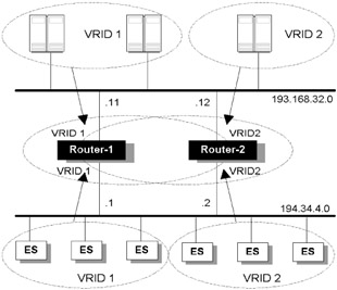
Figure 7.9: VRRP configuration with load sharing and resilience for a server farm.
In this configuration, both routers run VRRP on all interfaces, and on both LAN interfaces both routers will simultaneously participate in two VRRP groups. Half of the end systems install a default route to the IP address of Router-1 (194.34.4.1); the remaining end systems install a default route to the IP address of Router-2 (194.34.4.2). Router-1 is elected as the master for VRID 1, with a priority of 254, with Router-2 providing backup. In the same way Router-2 is elected master for VRID 2, with Router-1 providing backup. If either master should fail, the backup will automatically kick in. For example, if Router-1 dies, then Router-2 will operate as master for virtual IP addresses 194.34.4.2 and 194.34.4.1 until Router-1 resumes activity. On the server-side LAN we are doing effectively the same thing. Note that VRID-1 and VRID-2 are used on both LANs but are effectively operating as different groups.
This configuration enables load sharing through the routers, while also providing full redundancy and transparency. If more horsepower is required, then more than two routers could be configured in parallel.
7.3.9 Port hashing techniques
This technique may be implemented in switches or routers as a hash function to control flow destination based on flow criteria. Normally this is generally a proprietary feature, and the output of the function may be deterministic or non-deterministic (i.e., the designer can predict which physical interface will be used to output a flow based on input, or load balancing is entirely dynamic). Assume, for the sake of simplicity, that our hash function simply takes two addresses and outputs an interface ID using an XOR function, using bit positions to associate an interface. In this case we assume the switch has 16 interfaces, so we use a 4-bit mask to determine which port to use. Let us assume that an IP packet arrives with source address 195.66.3.6 and destination address 140.10.128.3:
11000011 01000010 00000011 00000110 = 195.66.3.6 // Class C address 10001100 00001010 10000000 00000011 = 140.10.128.3 // Class B address XXXXXXXX XXXXXXXX XXXXXXXX XXXX1111 0.0.0.15 // Interface Mask ----------------------------------- logical_XOR XXXXXXXX XXXXXXXX XXXXXXXX XXXX0101 = 5 // The Interface!
Note that I am not recommending this particular algorithm, just illustrating the concept. For a switch with only four active interfaces (as used in our example) the function could be configured (or could reconfigure dynamically) to adjust the length of the bit mask and, if necessary, wrap around if the number of active ports is not a power of 2. For more granular flow classification, the algorithm could hash the IP source and destination address and destination TCP or UDP port to generate an output interface. This would enable differentiation of applications such as FTP, SMTP, and Telnet.
If this algorithm is deterministic (as in our example), we would simply need to cable up the network topology consistently to be sure that flows are sent and received down the same path (this may be important for applications such as stateful firewalls); in effect we are demultiplexing flows through a physical infrastructure and then aggregating them on the other side. In Figure 7.10, we use this concept to scale firewall performance using high-speed switches (capable of operating at up to wire speed). The physical wiring in this case would typically be 10/100 Ethernet. The basic idea is that the bottleneck device (typically a device doing a lot of work, in this case a firewall) should be encapsulated (in the topological sense) inside a number of higher-speed devices. The encapsulated device sees only a proportion of the overall traffic, since the switch presorts flows and allocates them to specific physical interfaces. This enables devices such as firewalls to be scaled as many times as there are available interfaces at the switch. In Figure 7.10, a session is identified (fl) on Switch-1 and hashed to a specific interface. Physical cabling ensures that this interface is fed into Firewall-2, which simply outputs into Switch-2. The flow return is directed down the same physical path (this means that the hash function used on Switch-2 must be consistent, and cabling must reflect the output of the function to ensure that the return path is consistent.
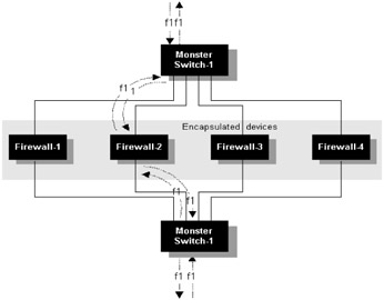
Figure 7.10: Deterministic flow hashing using two monster switches.
The main design restrictions are associated with the hash function and the physical topology. The hash function must have sufficient granularity to pick out application flows to enable a reasonable load distribution. On the other hand, the function needs to be fairly simple to avoid too many processing overheads per packet. There is therefore a trade-off between making this function fast and sufficiently fair. The other main issue is that the physical topology may need to be symmetrical and should exhibit consistently throughout. If a physical interface or cable breaks on either side of the encapsulated device, the flow send and return paths could be inconsistent. This may not be a problem if the encapsulated device does not need to maintain flow state information (a router), but this may be unacceptable to a more sophisticated device such as a firewall (e.g., if stateful inspection is being used). In this case the switch could implement a simple polling feature to test available paths and force interfaces to forward consistently on both sides, or some form of state synchronization could be used between switches to ensure that the hash function output is consistent for all flows.
Since this is a flow-based function, we are not talking about true load balancing. The actual load imposed on each encapsulated device will depend on the applications used and the number of flows. In a large network with reasonably diverse flows the loading should be evenly distributed. If one dominant source is present, loading may be less evenly spread. Note also that some commercial solutions use modulo-based hash functions; this will lead to uneven distribution depending upon the number of switches. If the switch runs into performance issues (assume the external paths in the topology are Gigabit Ethernet) it is possible to scale the switch design, as illustrated in Figure 7.11.
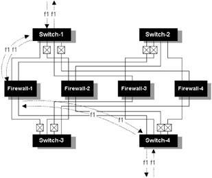
Figure 7.11: Deterministic flow hashing.
Distributed hashing techniques
Some implementations take a more intelligent approach to traffic flow distribution by clustering devices and using hashing techniques to allocate flows among group members. In general there are two methods employed, as follows:
-
Autocratic model—See Figure 7.12(a). Here we elect a master flow distributor for the cluster. The master receives all incoming packets, and, based on the flows identified and the number of members in the cluster, flows are bounced back and directed to individual group members for processing.
-
Democratic model—See Figure 7.12(b). Here we use a stateful protocol between group members to distribute flow allocation (a master may still be elected for controlling flow state updates, but this is analogous to the role of the designated router in a link-state protocol). This is really an improvement on the first technique in that traffic is no longer redirected through the single master device. Each group node knows which flows to handle and which ones to discard. The downside is that all traffic needs to be seen by all members of the cluster.
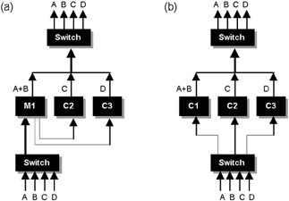
Figure 7.12: Distributing flows using hashing techniques. Here, four flows (A, B, C, and D) are fed into the cluster. (a) An autocratic model, where a master (MI) is elected and performs flow distribution at the ingress port. (b) A democratic model, where each node is aware of the flow states being handled by other members of the cluster.
At first it may seem that the autocratic method adds little value, since we need to process and classify all incoming traffic at the master in order to decide how to distribute it. However, consider a device such as a firewall or VPN termination node. These devices perform significant packet processing functions (particularly if high-speed encryption is required for thousands of concurrent sessions). For this class of device, simply classifying and bouncing incoming traffic between cluster nodes is a negligible overhead in terms of this overall processing requirement.
In either model it is important that the algorithm handle cluster node introduction and removal dynamically. This is a fundamental requirement, since we need to deal gracefully with a cluster member malfunction (including failure of a master), so as not to cause major disruption to the whole group. For applications such as VPN, stateful firewalls, or transaction processing, it is also highly desirable that flows be switched transparently in the event of a failure, so that sessions remain alive regardless. For these applications it may also be desirable that flows be handled symmetrically, so that send and return flows for each individual application session are routed through the same cluster node. We have also assumed so far that nodes in the cluster have equivalent resources (processor speed, memory size, etc.). With either model, more sophisticated algorithms may allow nodes to be mixed, with the flow allocation reflecting any differences in processing capability. Note that in both designs a single switch is used on either side of the cluster; in practice, this could be deployed as multiple switches for scalability and high availability.
|
|