Hacking BIOS
Contemporary chipsets have an enormous number of settings, even the brief listing of which would take several hundreds of pages of text printed in small font. However, BIOS Setup allows the user to access only a limited number of these settings and configures the remained settings itself, assuming that it would be much better not to provide the user with full power over the machine. For fine-tuning of the chipset for maximum performance, it is necessary to modify BIOS code or, simply speaking, hack it. Hacked versions of the firmware can be found on certain forums. As a rule, code diggers love to exchange hacked firmware. Use such firmware at your own risk, because it is potentially dangerous. If you burn the chipset, memory, or processor, it would cause only half of the trouble. It would be much worse if the motherboard ends in clouds of smoke. Nevertheless, those who don't take risks don't win; therefore, hacked firmware is popular.
Do you want to hack your own BIOS? This isn't a trivial task. To achieve this goal, you'll have to spend lots of time reading the documentation, and lots of effort working with debugger and disassembler, before you'd cast some light on BIOS mysteries. You'll need IDA Pro or any other disassembler of your choice, detailed technical documentation for your chipset (not to be confused with promotion materials), and a set of utilities for packing and unpacking BIOS code and computing the checksum (as a rule, these can be downloaded from the manufacturer's site). In the worst case, you'd have to disassemble the BIOS-reprogramming utility and write this toolset on your own.
Finally, you'll need the image of BIOS that you are going to hack. There are two ways of obtaining this image: taking a dump from the existing BIOS or downloading it from the manufacturer's site. Both ways are error-prone . BOOTBLOCK often unpacks only the "required" part of BIOS, not the entire code. As a rule, it then mixes the pages in memory so that access to the original ROM becomes impossible . In addition, it is unclear, which format of the BIOS image should be correctly interpreted by the BIOS-upgrading program. Updateable firmware is much better in this respect. However, as was mentioned earlier, some of them include only part of BIOS code. Therefore, download all available firmware, not just the one you have chosen .
Before loading the firmware into the disassembler, it is desirable to unpack it using an appropriate utility downloaded from the site of the BIOS developer. To tell the truth, such utilities do not always unpack all microprograms; therefore, it would be much better to unpack BIOS manually by disassembling BOOTBLOCK using HIEW or IDA. If the program for unpacking your version of BIOS is not available, you'll have to proceed this way in any case.
As a rule, BOOTBLOCK is always located at the end of the image; however, the location of its entry point is usually unknown. After the power-on or reset, the processor passes control at the FFFFFFF0h address; however, you usually do not know beforehand how the image is mapped to the memory. Assuming that the end of the image matches the FFFFFFFFh address (which is usually the case), then the entry point will be located at the 10h byte, counting from its end.
Usually, at that address you'd find something like jmp far , which corresponds to the EAh opcode, surrounded by meaningful text strings, such as BIOS release date. For example, consider Listings 31.3 and 31.4.
| |
seg000:7FFE0 41 30 30 30 39 30 30 30+aA0009000 DB 'A0009000',0 seg000:7FFE9 00 DB 0; seg000:7FFEA 00 DB 0; seg000:7FFEB 00 DB 0; seg000:7FFEC 00 DB 0; seg000:7FFED 00 DB 0; seg000:7FFEE 00 DB 0; seg000:7FFEF 00 DB 0; seg000:7FFF0 ; -------------------------------------------------- seg000:7FFF0 EA AA FF 00 FO jmp far ptr 0F000h:0FFAAh seg000:7FFF0 ; -------------------------------------------------- seg000:7FFF5 30 35 2F 31 38 2F 30 34+a051804 DB '05/18/04' ,0 segOOO:7FFFE FC 7D DW offset unk_17DFC
| |
| |
seg000:3FFE8 36 41 36 4C 4D 50 41 45 a6a61mpae DB '6A6LMPAE' seg000:3FFF0 ; ------------------------------------------------------- seg000:3FFF0 EA 5B E0 00 F0 jmp far ptr 0F000h:0E05Bh seg000:3FFF0 ; -------------------------------------------------------- seg000:3FFF5 2A 4D 52 42 2A aMrb DB '*MRB*'
| |
Now, it is necessary to convert the target jump address to the actual address. For example, if the seg000:7FFF0 address physically is equal to F000:FFF0h , then the physical address F000:FFAA is mapped to seg000: 7FFAA . The next case is similar: If seg000:3FFF0 is F000:FFF0 , then F000:E05Bh is translated into seg000:3E05Bh . To avoid these computations , it is possible to instruct IDA to change the base segment address so that seg000:70000 would correspond to segxxx:0000 .
If you encounter meaningless garbage, this means that either this code section is packed or that you have made an error when determining its bit length. The main BIOS code is 16 bits; however, it might contain lots of 32-bit fragments called by the operating system. It is also possible that you started disassembling from the middle of an instruction. How do you correctly determine the starting position for disassembling when dealing with a continuous byte stream? A good result can be achieved by searching for bytes such as E8h (corresponding to the start of the near call command) and EAh (corresponding to the jmp far command. Also, find all text strings and restore all cross-references to them. To achieve this, it is necessary to find the string offset using a direct search in the memory. Do not forget that the least significant byte of the offset must be located in the leftmost position; in other words, if the string is located at the seg000:ABCD address, then it is necessary to look for CD AB (see Hacker Debugging Uncovered by Kris Kaspersky).
Correctly disassembled code appears approximately as shown in Listing 31.5. Now you can hack it, for example, by replacing the "Memory Testing" string with "matrix loading" or something of the sort .
| |
seg000:2DIC CLI seg000:2D1D mov si, offset aMemoryTesting ; "Memory Testing : " seg000:2D20 CALL sub_1CC44 seg000:2D23 PUSH 0E000h seg000:2D26 PUSH offset loc_12D34 seg000:2D29 PUSH 0EC31h seg000:2D2C PUSH offset locret_13470
| |
In the course of disassembling, you'll encounter lots of attempts at accessing input and output ports. To understand their physical meanings, consult the technical descriptions of the chipset. AMD and Intel provide all supplementary documentation for free. For other manufacturers, the situation is slightly worse. If you cannot obtain the required technical description, consult the notorious Interrupt List by Ralf Brown.
The best tool for hacking BIOS code is HIEW, because reassembling the disassembled listing won't produce any positive result. Having completed this, process the hacked file with the packing utility (or pack it manually, having computed the checksum beforehand). Then try to "feed" the resulting code to BIOS flashing utility. If everything was done correctly, rejoice; otherwise , see " BIOS Versions That Can Stick up for Themselves ."
Inside a Flashing Utility
To begin with, it is necessary to point out that it is practically impossible for a programmer to write a universal flashing utility suitable for all BIOS models. This is because methods of controlling BIOS flashing voltage, methods of allowing write operations in Flash, specific features of RAM shadowing, and algorithms of disabling BIOS caching are too dissimilar for different chipsets and BIOS models.
However, if you are eager to try, consult the following sources of information: disassemble the commercial BIOS-updating utility and analyze its algorithm. Then, if necessary, use its key fragments. Technically, this is the most correct method. However, the following difficulties might be encountered : First, the utility might be missing; second, disassembling is too labor- intensive and requires enormous amounts of time, to speak nothing about appropriate skills.
As a variant, consult the Interrupt List or search the Internet. If you are lucky enough, you'll find all of the required information. For instance, the INT 16 interrupt is responsible for flashing AMI BIOS. This interrupt is covered in the finest detail in the Interrupt List.
Award BIOS models do not have such a possibility. They are programmed using input/output ports. Architecturally, the Flash chip is connected to the south bridge of the chipset. The most correct but the least romantic approach is consulting the description of the chipset or, to be more precise, its south bridge. For distinctness, let this be AMD 756. The "Flash Memory Support" section of the manual contains the following: "Support for programmable Flash memory is provided by enabling write cycles to BIOS ROM regions . Bit 0 of the ISA Bus Control register (function 0 offset 40h ) is provided to enable write cycle generation." Everything is clear and straightforward. There is no need to disassemble anything. However, if a malicious hacker would try to ruin someone else's BIOS, this attempt would fail, because other chipset behave differently in this respect.
There are lots of ready-to-use BIOS flashing utilities supporting practically all known types of BIOS models. Most of them are supplied with the source code. One such utility is the famous UniFlash, which can be downloaded from http://www.uniflash.org/ .
Technique of BIOS Flashing
Early models of the Flash BIOS were often ruined during the updating procedure. The cause of this phenomenon could be a trivial system hang-up during the updating process or a power failure of an incorrect version of BIOS. After that, the user had to either discard the motherboard or rush to search for a hacker with the programmator. The first solution was too expensive, but the second approach was too difficult and troublesome . Thus, motherboard manufacturers had to search for a solution. As the result, they equipped BIOS with advanced protection and recovery tools, which will be described later in this chapter (see " BIOS Versions That Can Stick up for Themselves " ). Today, a user can update contemporary BIOS models without worrying. Nevertheless, it is strongly recommended that you provide yourself with an uninterruptible power supply (or at least warn everyone in your house that you are updating BIOS, so that they do not experiment with the mains). Then, enter BIOS Setup and choose the default configuration, because, as a rule, it is the most stable and reliable. Also make sure that there are no hardware problems in your system. Your computer must run MS-DOS without freezing. If your computer is freezing under MS-DOS, this indicates that BIOS firmware doesn't cause the problems. Note that if the computer freezes when the BIOS flashing procedure is in progress, you'll have more serious trouble.
Having completed all preparations , download the new BIOS version from the site of the motherboard manufacturer. If this version was released today or yesterday , do not rush to update BIOS. Wait several days, because otherwise you risk encountering serious errors of the developers (this happens to anyone from time to time). It is strongly recommended that you avoid unofficial sources and "hacked" firmware, although the risk is not too serious because it is practically always possible to recover the corrupted BIOS.
BIOS updating can be disabled either by using the switch on the motherboard or by setting the Update options in BIOS Setup. Consult the user manual to eliminate all obstacles to successful BIOS updating.
Techniques of carrying out BIOS flashing procedure vary from utility to utility. The only advice that I can give in this situation is to carefully study the documentation supplied with the specific utility, paying attention even to the minor details. Practically all flashing utilities are console applications that must be run under MS-DOS (Fig. 31.4). Do not even try to start them under Windows unless the application instructs you to do so (an example of such an application is WinFlash, which was initially designed for flashing BIOS from under Windows).
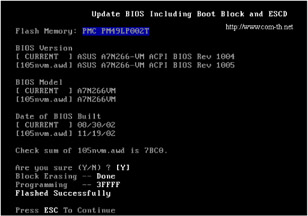
Figure 31.4: Interface of a typical BIOS flashing utility
As a rule, the installer utility is supplied with the program. The installer automatically creates the setup diskette. Before using the setup diskette, make sure that it was written without failures. To achieve this, remove the diskette and insert it again to make Windows read it anew instead of taking the data from the cache. Make sure that the diskette has enough space for writing the current firmware (the flashing utility must save it). As a rule, 200 to 500 KB is enough for this purpose. Do not save the current firmware to the newly-formatted diskette because the diskette also must contain an emergency recovery program, which automatically starts when booting from the diskette.
After completion of the flashing process, reset the CMOS (if the flashing utility didn't do this), because the new BIOS version might use a different format for storing configuration data. The new format might be incompatible with the one used previously, and this might cause conflicts. After rebooting and successful completion of the POST routine, enter BIOS Setup and find the Reset configuration option, which would reset all settings set by the previous BIOS version. Finally, after loading Windows (if it doesn't refuse to boot), start the Device Manager and let it do its job. The devices defined as unknown or conflicting now must be defined correctly. In the worst case, you'll have to reinstall Windows. Note that if you were updating BIOS to activate Hyper-Threading, you'll have to reinstall the system anyway, because the uniprocessor kernel is principally unable to support several processors and replacement of the kernel is the operation that requires you to have a strong nervous system.
BIOS Versions That Can Stick Up for Themselves
If the motherboard appears to be dead after BIOS flashing, do not panic. Look at the motherboard carefully and see if there is a BIOS recovery jump (as a rule, it is present on all motherboards from Intel).
In general, there are lots of technologies intended for protecting BIOS against incorrect updating. The most popular among them are Die Hard Lite, Die Hard I and II, and Dual BIOS.
Die Hard Lite BIOS architecturally is a tiny memory region inside BIOS (Fig. 31.5). This memory region, called the boot kernel, is logically or physically write-protected. It contains the boot loader with minimal functionality and supports an ISA video adapter. Note that if the motherboard doesn't have ISA slots, the boot kernel won't support anything, because PCI support is too bulky for it. The boot loader reads the original firmware from the diskette, provided that you saved it before flashing BIOS and that the diskette doesn't contain any bad sectors. In other words, this is a primitive technology. Still, it is better than no protection.
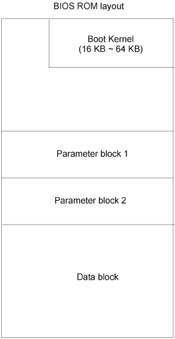
Figure 31.5: Die Hard Lite supports emergency recovery of the firmware from the backup copy saved to the diskette by leaving the boot kernel intact
Die Hard BIOS (I) is made up of two memory chips, each carrying fully functional BIOS code. The first chip, called Normal Flash ROM, is writable. The second chip, called Rescue ROM, is write-protected. In case of problems, it is always possible to switch to the Rescue ROM chip by resetting the jumper on the motherboard, and repeat the attempt at flashing BIOS, taking previous errors into account (Fig. 31.6). The main drawback of this technology is that rollback always reverts to the oldest BIOS version while the user might prefer the newer one.
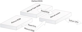
Figure 31.6: Die Hard BIOS is made up of two memory chips, one writable and one not
Die Hard BIOS II is an improved version of the Die Hard technology. Now both chips are equal in rights (Fig. 31.7), and each of them can be updated. If the main BIOS was updated successfully, the user can also update the backup BIOS, in which case the newest firmware version will always be available, no matter what happens with the BIOS chip.
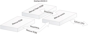
Figure 31.7: The Die Hard II chip is made up of two chips that are equal in rights. Both chips can be flashed
Dual BIOS is a variant of the Die Hard II technology but differs from it in design solutions. Like Die Hard II, it uses two equal memory chips; however, the user can switch between them manually, by resetting the jumper at the motherboard, and programmatically. The second method of switching doesn't require the user to open the case (which might be sealed) to access the jumpers . By the way, this technology could be implemented on your own, according to the method shown in Fig. 31.8. Manually implemented Dual BIOS appears as shown in Fig. 31.9.
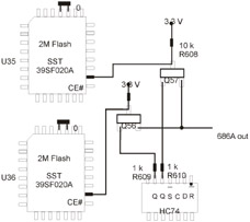
Figure 31.8: Dual BIOS is a variant of Die Hard II
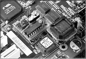
Figure 31.9: Manually implemented Dual BIOS
BIOS Versions That Cannot Stick Up for Themselves
Is it possible to reanimate the ruined BIOS, if the motherboard appears dead and its design doesn't make provision for emergency recovery? There are at least two approaches. The best and safest way is using the programmator, which can be purchased practically at any radio store (make sure that it supports the required type of Flash memory). The programmator must be supplied with the user manual, which you must carefully read and observe all requirements and instructions. If there is no user manual, consult the seller. As an alternative, you can make a programmator (an example of such a device is shown in Fig. 31.10).
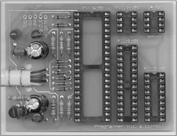
Figure 31.10: A Self-made programmator
If you do not have a programmator at your disposal but have the same motherboard, then remove the BIOS chip from it, wrap it with cotton thread, and insert it loosely into your computer. Then boot from the system diskette containing the flashing utility. Without shutting the system down and without switching it off, carefully remove BIOS from the slot, and insert the original chip, trying to avoid short-circuiting the system. If everything goes correctly and you do not damage anything, you'll be able to make another attempt at flashing BIOS. Hopefully, this time you'll succeed.
EAN: 2147483647
Pages: 164