QoS Options
Obviously, the ultimate Quality of Service would be if we were able to guarantee that every packet/frame on the network were delivered reliably, in the correct sequence, and with zero delay. Well, guess what-that's not going to happen! But a variety of techniques can be applied to try to get close enough to the end of the rainbow to allow the applications to manage the rest themselves.
The following parameters are considered essential for measuring and providing any QoS:
-
Service availability
-
Frame loss
-
Frame order
-
Frame duplication
-
The transit delay experienced by frames
-
Frame lifetime
-
The undetected frame error rate
-
Maximum service data unit size supported
-
User priority
-
Throughput
Two main mechanisms exist for dealing with end-to-end QoS, Differentiated Services and Integrated Services. Both are contenders for the ultimate solution, but we will focus on Differentiated Services because that's what Cisco uses with Ethernet.
| Note | The Integrated Services model involves setting up an end-to-end connection across an internetwork of RSVP-enabled routers using an new IP-based signaling protocol called Resource Reservation Setup Protocol (RSVP). RSVP routers request and reserve bandwidth across an internetwork and release it back to the internetwork after the connection is terminated. |
The Differentiated Services Model
The QoS implementation in Catalyst switches is based on the Differentiated Services (DiffServe) architecture. This reference model states that packets are marked (classified) at the entry point into the network, and that every subsequent router or switch, implementing hop-by-hop forwarding, uses the classification to try to match the forwarding process to the classification. This is achieved by each DiffServe router in the path having a locally configured queuing priority for forwarding marked packets. Non-DiffServe-enabled routers will simply forward packets based upon default queues. Figure 9.6 shows the DiffServe architecture, with routers in the end-to-end path either being in the domain or without. The entry point to the domain is called the ingress, and the exit point is called the egress.
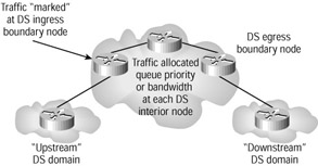
Figure 9.6: Differentiated Services model
At layer 3, this classification and marking is established by setting bits in the IP Type of Service (TOS) field to differing values. At layer 2, however, this is a little more difficult, as there are no fields inside legacy Ethernet available for this purpose. Even so, there are some clever mechanisms that allow us to map layer 2 priorities to layer 3.
The basic QoS model underlying all efforts is closely related to the DiffServe architecture. Shown in Figure 9.7, it consists of a series of discrete stages. First, the packets are classified and tested to see if they conform to the configured classification. This stage is called policing.
Next, the packet is marked and forwarded to the DiffServe network, where the marking will be used to set priorities in queues and establish any other forwarding rules, before reaching the egress point. The last router or switch in the path forwards the data to the target client according to locally configured rules.
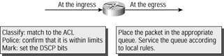
Figure 9.7: Basic QoS model
| Tip | It is not a condition of basic IP that routers understand the TOS or DS fields. Non-DiffServe routers in a path will treat the IP datagram in the same way as all other datagrams, forwarding it in a best-efforts fashion. This is quite useful because it means that DiffServe is easy to implement in phases on a network. |
DiffServe uses some specific bits in the IP header to mark the service class required. All DiffServe routers understand these settings and administrators are responsible for configuring router queues in such a way as to best meet the needs of the specific traffic class. The DiffServe field is part of the IP header, which is extended and changed slightly from the original TOS field.
The original IPv4 TOS field was defined years ago in RFC 791, when nobody had any idea how the Internet and its applications would pan out. This single octet has 3 bits of Precedence configurable as a group, providing seven levels of Precedence. In addition, a further 4, individually configurable, bits are available to request one of four types of service, with 1 bit unused (which must be zero):
-
Minimize delay
-
Maximize throughput
-
Maximize reliability
-
Minimize monetary
A replacement header field, called the DS field, is defined in RFC 2474, which is intended to supersede the existing definition. Six bits of the DS field are used as a Differentiated Services Code Point (DSCP) to select the PHB a packet experiences at each node. A 2-bit currently unused (CU) field is reserved. All 6 bits must be tested by DiffServe-compliant routers.
There is no backward compatibility with the TOS fields, but the implementation of one does not prevent implementation of the other. In either case, the actual forwarding mechanism applied by each router in the path is established by local configuration of queues and priorities, and is likely to be proprietary, so routers could forward along planned paths according to either TOS or DS bits.
In order to classify packets, we need to determine some traffic types to use as templates. Table 9.1 defines traffic types.
| Traffic Type | Characteristics of Traffic Needs |
|---|---|
| Network Control | High requirement to get through to maintain and support the network infrastructure |
| Voice | Less than 10 milliseconds delay |
| Video | Less than 100 milliseconds delay |
| Controlled Load | Important applications |
| Excellent Effort | Best efforts for important users |
| Best Effort | Ordinary LAN priority |
| Background | Bulk transfers, games, and so on |
IEEE 802.1p
The IEEE 802.1p standard defines important methods for traffic class expediting and dynamic multicast filtering, thus providing Quality of Service at the MAC level. This standard may be considered an extension to the 802.1Q standard discussed in Chapter 3, 'VLANs, Trunks, and VTP.' Three bits are allocated inside the 802.1Q insert that were unspecified at the time, but have been allocated by 802.1p.
802.1p establishes eight levels of priority that are conceptually similar to the 3 bits specified by IP Precedence. Layer 2 switches can prioritize data in their output buffers according to these priority bits, and many layer 3 switches are capable of 'mapping' the 802.1p Precedence to the TOS or DiffServe fields inside IP so as to achieve end-to-end QoS across integrated switched and routed internetworks.
Applying the QoS Model
The first stage in determining how the switches and routers in the network will prioritize traffic is the classification process. Essentially, the idea is to somehow mark traffic with an indication that it should be treated differently from packets with dissimilar marking.
The second stage is traffic policing. This is the process whereby a switch/router determines whether the frame/packet matches the preconfigured profiles. Packets that exceed specified limits are considered to be nonconforming. The policing process specifies the action to take for packets by either setting bandwidth limits for conforming traffic, or dropping or remarking nonconforming traffic.
The third stage is to actually mark the frame/packet. Data can be marked at layer 2 (in the 802.1p header) or at layer 3 (inside the IP header), depending upon the device. Switches that operate at layer 3 are able to mark at either layer, but switches operating purely at layer 2 are able to mark only the frame.
So if the switch is a layer 3 switch, we have the option of forwarding a packet with QoS. Then, using the general principles of traffic types, we need to 'map' the traffic type to a TOS or DiffServe number. After the packet has been through the classification, policing, and marking processes, it is assigned to the appropriate queue before exiting the switch. If the switch has received the packet inside an 802.3 frame with 802.1p priority specified, this process may be automated. If not, then we must map it manually.
Finally, the packet must be forwarded out of a shared output buffer onto the media toward the next hop. This is usually accomplished by establishing a queuing process and placing traffic into different queues according the policies defined earlier.
Prioritizing Traffic Classes
Traffic marking is normally carried out using mapping commands. There is a wide range of mapping commands in the Cisco IOS, including route-maps (for manipulating route parameters), crypto-maps (for establishing encryption parameters), and others. The ones we are most interested in are the policy-maps and the class-maps.
All IOS maps have some things in common. Maps begin with a match command, which unambiguously identifies some form of traffic, at the frame, packet, or even application layers. This would involve the additional use of an access list. Class-maps allow for the matching of an IP address, a protocol, or an incoming interface.
Once traffic has been matched, then the map (sometimes the same map, sometimes a 'sister' map, as in the case of policy- and class-maps) is used to 'set' an attribute. A wide variety of attributes can often be associated with matched traffic in this way, but the policy-map allows only for the setting of the DSCP code point. Figure 9.8 shows where the marking takes place in both the Data Link and Network PDUs.
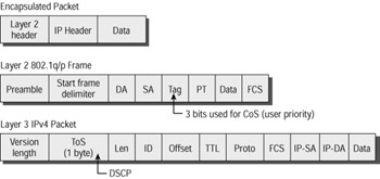
Figure 9.8: Frame and packet marking
Queuing Mechanisms
A number of different queuing mechanisms exist on Cisco layer 2 and layer 3 switches. The reason for this is that across the globe, different network managers require different prioritization for different networks running a wide variety of legacy, common, and emerging applications. No single queuing mechanism could support these diverse needs, so several mechanisms exist. It is up to the intelligent network administrator to apply the method available for their network that best suits their needs. Here is a short list of the most prevalent methods available across the spectrum of Cisco layer 2 and layer 3 switches:
First In, First Out Queuing First in, first out (FIFO) queuing transmits frames/packets according to the timed arrival of the first bits in the frame/packet at the input interface. This is often the default method.
Weighed Fair Queuing Weighed Fair Queuing (WFQ) places data into different queues according to the conversation index associated with each packet. The conversation index is a term applied to different applications, whose packets are then marked with a number inside the switch or router. The selection of the data type and queue is internal and proprietary, but results in low-volume interactive traffic (voice) being granted higher priority than high-volume non- interactive traffic (FTP).
Custom Queuing Custom Queuing allows administrators to create up to 16 queues, each with configurable sizes and forwarding thresholds. Data is placed in queues according to access lists, and queues are emptied on a round-robin basis.
Priority Queuing Priority Queuing allows the administrator to create a number of queues and configure the size of each. Data is placed into queues according to access lists, and queues are emptied on a strict priority basis. Packets in the highest priority queue are always transmitted first, and packets in lower priority queues are not transmitted until the queues higher up are emptied.
Weighted Round Robin Queuing Weighted Round Robin Queuing is a simplified version of custom queuing. A fixed number of queues are serviced in round-robin fashion, each being configurable only as to the size of the queue.
Multistage Queuing Multistage Queuing can be implemented on some platforms, and involves the creation of multiple queuing processes in a dependency fashion. For example, a mixture of priority and WFQ could be used.
Figure 9.9 shows how packets arriving at three interfaces at the same time need to be sorted into an output queue to be transmitted serially. Of course, it is in the output queue that we can influence packet delay by arranging how the queue works.
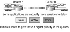
Figure 9.9: Queuing overview
Auto-QoS
Obviously, implementing QoS can be an administrative headache. Some configurations have the potential to affect application delivery across a wide spectrum of the network, and without practical skills and experience it's easy to make mistakes. To help administrators build QoS- based networks with the minimum of effort, Cisco has created something called auto-QoS.
Auto-QoS can be used to simplify the deployment of QoS features. Auto-QoS makes certain assumptions about the network design, allowing the switch to prioritize different traffic flows and use the output queues appropriately instead of just using the default QoS behavior of best- efforts service from a single queue. Auto-QoS uses the input packet label and traffic type to automatically classify traffic. The switch then uses this classification to place traffic in the appropriate output queue.
One of the main features of auto-QoS is the ability of the switch to identify ports that have IP telephones attached to them and allocate sufficient buffer space to afford the VoIP (Voice over IP) calls the correct QoS. This does not just apply to the ports with the IP phones connected, but also to uplinks that carry the VoIP calls to the next switch. This process is called trust.
Trust allows for ports that may carry VoIP traffic (but not actually have IP phones directly connected) to recognize that a packet marked as carrying such a service must be afforded the same QoS as if it were directly connected, and therefore proven to be VoIP. Trust is configured across a QoS domain. Packets are marked only at the ingress to the domain and trusted from there on, obviating the need to mark again at every switch or router.
| Note | Trust will be pretty important in the future, when all networks start to use QoS. Obviously, QoS is not going to be free, and ISPs will probably charge more for better QoS on the Internet. It follows that when an arriving packet demands a better QoS because of some bits set in an IP header, we should be certain that we are prepared to agree to those demands; otherwise the system would be open to abuse. Disreputable users would be able to manipulate the DSCP code bits to create higher priorities for web browsing, for example. |
Configuring QoS on Cisco Switches
The Cisco range of switches is currently undergoing one of the largest series of changes I have ever seen. As you may know, Cisco became one of the largest switch vendors in the world, partly by buying up some of the best competition. Companies such as Kalpana, Grand Junction, and Catalyst all provided input to the range. The result has been a mixture of operating systems and command-line interfaces that Cisco engineers and technicians have had to learn.
As Cisco standardizes the range, we are also experiencing an emerging need for something better than best-efforts data delivery on our computer networks. The combination of the newer operating systems, new switch architectures, and new application demands means that there is a lot more to learn. Because the process is ongoing, not every Cisco switch will support every QoS feature. And because the IOS now plays such a large part in all this, new versions of the IOS may offer enhancements over previous versions.
In this section, I will cover the main commands used in the three current operating system options, CatOS and the standard and enhanced IOS images. But you need to stay up-to-date on this, because a major new IOS revision will almost certainly cause some things to change.
2950 Series Switches
The 2950 switch transmits network traffic in the following fashion. Frames are classified by assigning priority-indexed Class of Service (CoS) values to them and giving preference to higher- priority traffic such as telephone calls.
Each transmit port has a default normal-priority transmit queue and may be configured with up to four additional high-priority transmit queues. Frames in the high-priority queue are forwarded before frames in the normal-priority queue. Frames are forwarded to queues dependent upon the defined priority-to-queue mapping. Queues can be emptied using strict Priority Queuing or Weighted Round Robin Queuing as desired.
If your 2950 switch is running the standard software image, there are some restrictions on what you can configure. In fact, you are limited to configuring the CoS priorities and the WRR settings. To do this, use the wrr-queue cos-map global command to establish the queues, and the wrr-queue bandwidth statement to set the queue thresholds if needed.
Terry_2950#conf t Terry_2950(config)#wrr-queue ? bandwidth Configure WRR bandwidth cos-map Configure cos-map for a queue Terry_2950(config)#wrr-queue cos-map ? <1-4> enter cos-map queue id (1-4) Terry_2950(config)#wrr-queue cos-map 1 ? <0-7> cos values separated by spaces (up to 8 values total) Terry_2950(config)#wrr-queue cos-map 1 0 1 Terry_2950(config)#wrr-queue cos-map 2 2 3 Terry_2950(config)#wrr-queue cos-map 3 4 5 Terry_2950(config)#wrr-queue cos-map 4 6 7 Terry_2950(config)#wrr-queue bandwidth 10 20 30 40 Terry_2950(config)# Terry_2950#
If your switch has the enhanced image, you will be able to carry out classification and marking in addition to being able to perform DSCP mapping.
The example shown here will identify a particular traffic stream, identified by MAN address, and associate a DiffServe value with it. First, we need to establish the way that we will identify the traffic to be classified. Use the class-maps name global command to define the match criteria when classifying traffic.
Terry_2950(config)# class-map terry1 Terry_2950(config-cmap)# match access-group 701 Terry_2950(config-cmap)# exit
There are a selection of match options inside a class map:
Terry_2950(config-cmap)#match ? access-group access group input-interface Select an input interface to match mpls Multi Protocol Label Switching values protocol Protocol <cr>
In this example, we will use an access list in conjunction with the class map to clearly identify the traffic to be classified.
Terry_2950(config)#access-list 701 permit 0011.2345.6789 00aa.1234.5678
Finally, we need to determine what the classification will be. Use the global configuration command policy-map name to determine the classification criteria to be set for incoming traffic.
Terry_2950(config)#policy-map macpolicy1 Terry_2950(config-pmap)#class terry1 Terry_2950(config-pmap-c)#set ip dscp 56 Terry_2950(config-pmap-c)#exit Terry_2950(config)#int fa0/1 Terry_2950(config-if)#service-policy input macpolicy1
| Tip | For a full explanation of the differences between the standard and enhanced images available on the 2950 switch range, see Chapter 10, 'Catalyst Switch Technologies.' |
3550 Series Switches
The 3550 supports an entirely greater range of QoS options because of the layer 3 capability of the hardware and the IOS. There is, in fact, a good case for referring to the 3550 as a multiport router with layer 2 capabilities rather than a switch with layer 3 capabilities.
Essentially, the combined layer 2 and layer 3 QoS functionality means that the switch can classify traffic using sophisticated access lists, mark at both layers, forward using either DSCP or 802.1p priority bits, and even translate from one to the other. This combined functionality involves accepting the default mapping that places DSCP traffic into Ethernet frames with a closely related CoS (or maps the IP datagram inside an incoming Ethernet with CoS set to the IP datagram itself as a DSCP). If the defaults are not suitable for your network, you can use an mls qos-map to establish your own translation values.
This large range of options means that we have to restrict ourselves a little, because the subject of QoS as applied by routers and other layer 3 devices is large enough to warrant a book all by itself. In fact, it is one of the core subjects of a new advanced Cisco certification, the CCIP (Cisco Certified Internetwork Professional). So, to stay on target, we will concentrate our efforts on those configurations that are likely to appear on the BCMSN exam.
Configured QoS
To configure QoS on a 3550 switch, first enable QoS globally with the mls qos command.
The use of class-maps and policy-maps to define the match and classification criteria for incoming traffic is very similar to the way they are used inside the 2950.
Class-maps can be configured using an extension allowing the matching of either all or any of the criteria specified in the map. To manage this feature, use either the class-map match-all or the class-map match-any global commands. In addition, the class-map supports matching against a VLAN or a group of up to 30 VLANs. To select this match option, use the match vlan vlan- list c-map command.
The following example shows traffic arriving at interface gigabitethernet0/1, sourced from VLAN 66 or being already marked with an IP Precedence of 1, having the DSCP set to 63 at the ingress.
Terry_3550(config)#mls qos Terry_3550(config)#access-list 101 permit ip any any precedence 1 Terry_3550(config)#class-map match any terry2 Terry_3550(config-cmap)#match access-group 101 Terry_3550(config-cmap)#match vlan 66 Terry_3550(config-cmap)#exit Terry_3550(config)#policy-map ip_or_VLAN66 Terry_3550(config-pmap)#class terry2 Terry_3550(config-pmap-c)#set ip dscp 63 Terry_3550(config-pmap-c)#exit Terry_3550(config-pmap)#exit Terry_3550(config)#interface gigabitethernet0/1 Terry_3550(config-if)#service-policy input ip_or_VLAN66
If you are configuring QoS inside a trusted domain and you do not use auto-QoS, then you have to decide what to do about trust. If you wish to trust incoming CoS values, use the interface command mls qos trust cos to ensure that the CoS value in received traffic is trusted, and use the mls qos trust device cisco-phone command to specify that the Cisco IP phone is a trusted device and ensure that a non-trusted device does not misuse the CoS available. Remember to enable cdp.
Terry_3550(config)#int fa0/1 Terry_3550(config-if)#cdp enable Terry_3550(config-if)#mls qos trust ? cos Classify by packet COS device trusted device class dscp Classify by packet DSCP ip-precedence Classify by packet IP precedence <cr> Terry_3550(config-if)# mls qos trust cos Terry_3550(config-if)# mls qos trust device cisco-phone Terry_3550(config-if)#^c
Because trusted traffic will automatically gain access to the process whereby CoS is mapped to DSCP, there is an option to forward CoS values without changing the existing DSCP (and vice versa) through the switch. This is called pass-through, and can be configured for either option:
Terry_3550(config-if)# mls qos trust cos pass-through dscp
or
Terry_3550(config-if)# mls qos trust dscp pass-through cos
Auto-QoS
The implementation of auto-QoS simplifies the configuration of switches inside a trusted domain. First, enable QoS in the usual way, with the mls qos command:
Terry_3550(config)#mls qos
Now you have a choice. If the interface has an IP phone directly connected, use the commands shown next:
Switch(config)#interface fastethernet0/1 Switch(config-if)#auto qos voip cisco-phone
And if the interface is not directly connected to an IP phone, but is a trusted device, then enter this alternative:
Switch(config)#interface gigabitethernet0/1 Switch(config-if)#auto qos voip trust
| Note | Note that up to release 12.1(14)EA1 of the IOS, auto-QoS configures only the switch for VoIP with Cisco IP phones. |
4000 Series Switches
If your 4000 switch has been upgraded to run IOS, then the classification, marking, and forwarding of packets is the same as for the 3550. But when running the legacy CatOS operating system, the QoS options available for the 4000 series switches are relatively unsophisticated. This section describes the CatOS QoS options.
Each transmit port has three possible queues. There is one non-configurable queue and two queues where some configuration is possible. The drop thresholds can be configured, but tail drop occurs in all cases when the queue is full.
The switch has a default 802.1p CoS of 0 (zero), but this can be changed. In that case, all unmarked frames entering the switch are marked with the specified CoS value. Marked frames cannot be changed.
The default condition is for QoS to be disabled, so first you have to enable QoS on the switch. Take care that any configuration changes are carried out at an appropriate time, because some of them will reset ports, and possibly cause Spanning Tree instability if the network converges. You can turn on QoS using the set qos enable command.
The port type is defined by the number of transmit queues and the number of drop thresholds that are supported on the port. For example, the 2q1t port type supports two transmit queues each with a single configurable drop threshold.
| Tip | Port types on the Catalyst 4000 are dependent upon the hardware. Use the show port capabilities command to find out what port type you are configuring. |
To configure the CoS mapping and set the thresholds on a configurable port, use the set qos map port_type q# threshold# cos cos_list. The port type you will already know. You need to decide which threshold to apply to which queue, and the CoS values to map to the specified transmit queue. The following example shows the two queues on a 2q1t port being configured, one with CoS 2-4 and the other with CoS 5-7:
Terry_4000> (enable) set qos map 2q1t 1 1 cos 2-4 Terry_4000> (enable) set qos map 2q1t 2 1 cos 5-7 Qos tx priority queue and threshold mapped to cos successfully. Terry_4000> (enable)
To view the QoS configuration, use the show qos info config command.
Queuing Mechanisms
In addition to setting the QoS parameters, it is common for devices operating at layer 3 to have to receive and transmit packets, applying simple queuing mechanisms to the forwarding process. The most common of the configurable queuing mechanisms are Priority Queuing and Custom Queuing.
Priority Queuing
With Priority Queuing, data is placed into one of four different queues, defined as high, medium, normal, and low. These queues are emptied on a strict priority basis. Packets in the highest priority queue are always transmitted first, and packets in lower priority queues are not transmitted until the queues with higher priorities are emptied.
Configuration options available to the administrator include how to define the traffic, what queue to place the traffic into, and how large each queue should be. To define the traffic for a particular priority queue, use the priority-list global command.
Terry_3550(config)#priority-list 1 ? default Set priority queue for unspecified datagrams interface Establish priorities for packets from a named interface protocol priority queueing by protocol queue-limit Set queue limits for priority queues Terry_3550(config)#priority-list 1 protocol ? arp IP ARP bridge Bridging cdp Cisco Discovery Protocol compressed tcp Compressed TCP ip IP Terry_3550(config)#priority-list 1 protocol ip ? high medium normal low Terry_3550(config)#priority-list 1 protocol ip high ? fragments Prioritize fragmented IP packets gt Prioritize packets greater than a specified size list To specify an access list lt Prioritize packets less than a specified size tcp Prioritize TCP packets 'to' or 'from' the specified port udp Prioritize UDP packets 'to' or 'from' the specified port <cr> Terry_3550(config)#priority-list 1 prot ip high list ? <1-199> IP access list <1300-2699> IP expanded access list Terry_3550(config)#^Z Terry_3550#
To define the maximum queue size for a particular priority queue, use the priority-list priority- queue queue-limit global command:
Terry_3550(config)#priority-list 1 ? default Set priority queue for unspecified datagrams interface Establish priorities for packets from a named interface protocol Priority queueing by protocol queue-limit Set queue limits for priority queues Terry_3550(config)#priority-list 1 queue-limit ? <0-32767> High limit Terry_3550(config)#priority-list 1 queue-limit 5000 Terry_3550(config)#^Z Terry_3550#
Allocating the priority queue to a particular outgoing interface is achieved using the priority- list priority-queueinterface command.
Terry_3550(config)#int fastEthernet 0/1 Terry_3550(config-if)#priority-group 1 Terry_3550(config)#^Z Terry_3550#
| Tip | It is common to make the queue sizes increasingly larger as the priority decreases. Naturally, packets in the lowest priority queue stand a statistically greater change of spending more time in the queue, and it makes sense to allow the packets somewhere to wait. |
The following configuration uses access list 101 to place telnet traffic between any two hosts into the high-priority queue, uses access list 102 to place web traffic between any two hosts into the medium-priority queue, and places all other IP traffic into the normal-priority queue, while cdp traffic is placed into the low-priority queue. The list is applied to interface FastEthernet 0/24:
Terry_3550(config)#priority-list 1 prot ip high list 101 Terry_3550(config)#priority-list 1 prot ip medium list 102 Terry_3550(config)#priority-list 1 prot ip normal Terry_3550(config)#priority-list 1 protocol cdp low Terry_3550(config)#access-list 101 permit tcp any any eq telnet Terry_3550(config)#access-list 102 permit tcp any any eq www Terry_3550(config)#int fastEthernet 0/24 Terry_3550(config-if)#priority-group 1 Terry_3550(config)#^Z Terry_3550#
Custom Queuing
With Custom Queuing, data is placed into one of up to sixteen different queues, defined by queue number. These queues are emptied on a strict rotational basis. Once a queue's transmit threshold has been reached, the next queue is serviced, irrespective of whether the current queue still has packets in it.
Configuration options available to the administrator include how to define the traffic, what queue to place the traffic into, how large each queue should be, and how large each queue's service threshold should be.
To define the traffic for a particular custom queue, use the queue-list global command:
Terry_3550(config)#queue-list ? <1-16> Queue list number Terry_3550(config)#queue-list 1 ? default Set custom queue for unspecified datagrams interface Establish priorities for packets from a named interface lowest-custom Set lowest number of queue to be treated as custom protocol Priority queueing by protocol queue Configure parameters for a particular queue stun Establish priorities for stun packets Terry_3550(config)#queue-l 1 interface ? Async Async interface BVI Bridge-Group Virtual Interface Dialer Dialer interface FastEthernet FastEthernet IEEE 802.3 GigabitEthernet GigabitEthernet IEEE 802.3z Group-Async Async Group interface Lex Lex interface Loopback Loopback interface Multilink Multilink-group interface Null Null interface Port-channel Ethernet Channel of interfaces Transparent Transparent interface Tunnel Tunnel interface Virtual-Template Virtual Template interface Virtual-TokenRing Virtual TokenRing Vlan Catalyst Vlans fcpa Fiber Channel Terry_3550(config)#queue-l 1 interface fastEthernet 0/12 ? <0-16> queue number Terry_3550(config)#queue-l 1 interface fastEthernet 0/12 1 Terry_3550(config)#queue-l 1 interface fastEthernet 0/13 2 Terry_3550(config)#queue-l 1 interface fastEthernet 0/14 2 Terry_3550(config)#^Z Terry_3550#
To define the maximum queue size for a particular custom queue, use the queue-list queue- limit queue-number byte-count global command:
Terry_3550(config)#queue-list 1 ? default Set custom queue for unspecified datagrams interface Establish priorities for packets from a named interface lowest-custom Set lowest number of queue to be treated as custom protocol Priority queueing by protocol queue Configure parameters for a particular queue stun Establish priorities for stun packets Terry_3550(config)#queue-list 1 queue 1 ? byte-count Specify size in bytes of a particular queue limit Set queue entry limit of a particular queue Terry_3550(config)#queue-list 1 queue 1 byte-count ? <1-16777215> Size in bytes Terry_3550(config)#queue-list 1 queue 1 byte-count 10000 ? limit Set queue entry limit of a particular queue <cr> Terry_3550(config)#queue-list 1 queue 1 byte-count 10000 limit ? <0-32767> Number of queue entries Terry_3550(config)#queue-list 1 queue 1 byte-count 10000 limit 10 Terry_3550(config)#^Z Terry_3550#
Allocating the priority queue to a particular outgoing interface is achieved using the custom- queue-list custom-queueinterface command:
Terry_3550(config)#int fastEthernet 0/1 Terry_3550(config-if)#custom-queue-list 1 Terry_3550(config)#^Z Terry_3550#
The following configuration uses access list 101 to place telnet traffic between any two hosts into queue 1, uses access list 102 to place web traffic between any two hosts into queue 2, and places all other IP traffic into queue 3, while cdp traffic is placed into queue 4. Changing the queue sizes has the effect of 'fairly' allocating queue space to traffic:
Terry_3550(config)#queue-list 1 protocol ip 1 list 101 Terry_3550(config)#queue-list 1 protocol ip 2 list 102 Terry_3550(config)#queue-list 1 protocol ip 3 Terry_3550(config)#queue-list 1 protocol cdp 4 Terry_3550(config)#access-list 101 permit tcp any any eq telnet Terry_3550(config)#access-list 102 permit tcp any any eq www Terry_3550(config)#queue-list 1 queue 1 byte-count 2000 limit 25 Terry_3550(config)#queue-list 1 queue 2 byte-count 5000 limit 20 Terry_3550(config)#queue-list 1 queue 3 byte-count 10000 limit 10 Terry_3550(config)#queue-list 1 queue 4 byte-count 1000 limit 5 Terry_3550(config)#^Z Terry_3550#
| Note | The 16 queues are all configurable, but you only need to configure as many as you need or want to. A separate 17th queue is created by the router for use by systems traffic. This queue is not configurable. |
EAN: 2147483647
Pages: 174