Redundancy in Switched Networks
Redundancy is the art of ensuring that even when a component or service fails, network availability remains. This is obviously difficult to achieve in areas of the network where a single point of failure exists. One of the most common single points of failure is the default gateway used by non-routing hosts.
| Note | Here is a reminder of the basic IP connection procedure. When an IP host needs to access a second IP host, it knows the three things: its own IP address and mask and the address of the target. Using its own mask, a host decoded the target IP address in what is colloquially known as a test for adjacency. If the target host is on the same network, the host ARPs the target IP address directly. If the test for adjacency fails-the target is on a different subnet-then the host must send the data to a router. The most common method used to identify the default gateway is a statically configured default gateway. |
Under normal circumstances, if the default gateway is unavailable, the result would be that the host would not receive a reply to an ARP request, would not be able to create Ethernet frames addressed to the default gateway, and would be unable to send data outside the local subnet. Even if a second default gateway were configured on the host, there would be a delay while the host realized that the first default gateway was not going to reply.
There are other ways of allowing a host to find a router. Hosts could run passive RIP, which would allow them to listen to RIP routing updates from local routers and complete a proper routing table. This is common in some UNIX implementations, but is slow to converge and can use a lot of memory for the routing tables. The Internet Router Discovery Protocol (IRDP) and IPv6 with its ICMP router discovery hello packets may also be suitable. But most Microsoft Windows machines use the static default gateway configuration.
Cisco's Hot Standby Routing Protocol was designed to provide a solution to this perennial problem.
Hot Standby Router Protocol
The principles behind the Hot Standby Routing Protocol are marvelously simple. Two or more routers are configured in such a way that they act as a sort of cluster, creating a single, virtual router. Hosts are configured to use the address of the virtual router as their default gateway, and the Hot Standby Routing Protocol (HSRP) manages the decision-making regarding which router acts as the real default gateway.
Figure 9.10 shows the general layout of an HSRP group, with two routers sharing a standby IP address, and hosts using that address as their default gateway.
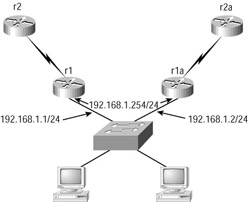
Figure 9.10: HSRP virtual router
Each member of the virtual router cluster can also act as a standard router, as long as all clients wishing to use the (non-virtual) router as their default gateway have the correct configuration-in other words, the standard IP address of the router interface.
HSRP Operation
Routers assume membership of an HSRP group after being configured with a standby IP address on an Ethernet interface in addition to the regular IP address. All routers in a group are configured with the same standby IP address, and an internal process in each router creates a standby MAC address of 0000.0c07.ac**, where the two stars represent the HSRP group number. (It follows that up to 256 HSRP groups could be configured.)
HSRP routers send hello packets, based on a 3-second default timer (configurable, of course), out of this interface, advertising the fact that they are now in a virtual router group. These hello packets contain the group ID of the HSRP group and the advertised priority of the router sending the hello.
Based on a priority system, one router assumes the role of the active router in the group. Other routers will adopt the standby condition. Active routers, on receipt of a packet that needs to be forwarded, will forward the packet. Standby routers will drop the packet, even though they also have a route.
This state remains static as long as the hello packets are continually received from the active router. Should these fail to arrive, then after the hold time has been exceeded, the next senior standby router assumes the active role and starts to forward packets. The default hold timer is 10 seconds, but is configurable.
Figure 9.11 shows the activity of the hello packets as they advertise their priorities on a specific standby group. The diagram shows router Terry sending hellos with a default priority of 100, and router Jack switched off. When router Jack is started, it sends out a hello with the configured priority of 105. Router Terry realizes that it is no longer the active router and now advertises that it is standby. Note that the hellos come from the 'natural' Ethernet IP address.
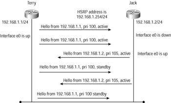
Figure 9.11: HSRP hello process
Preemption
Preemption is the process whereby the router with the highest configured priority becomes the active router. In the case of HSRP, the highest priority is the highest number in the range 0-255 (one octet).
The result is that if an active router fails, and then comes back online, it is able to take over being the active router once again. Without the preempt process, the standby router that had become active would remain as the active router until a new election process was started.
Interface Tracking
One additional advantage of the preemption process is that it allows the selection of the active router at arbitrary moments on a network without having to wait for formal elections. Thus if a standby router receives a hello from the active router and the active router is lower than its own configured priority, it will preempt and become active itself. By the same process, if an active router receives a hello from a router with a higher priority; it will cease to remain active.
This leads to a rather clever situation where a router can be configured to track another interface, with a view to reducing the standby priority on the standby interface should the other interface fail. There is a default reduction of 10, but this is configurable, allowing for complex scenarios to be created.
Multiple HSRP Groups
Within a group of VLANs, there will be more than one default gateway specified. If the Cisco advice of a subnet per VLAN is followed, then there will be the same number of default gateways.
Redundancy is both expensive and necessary, but we need not create full redundancy by having each default gateway backed up by another physical device. We can use multiple HSRP groups to do this in a more cost-effective fashion. One router could be used to act as the standby router for several different groups.
Furthermore, it is possible to create two groups on a pair of routers, and make each router active in one group and standby in the other. In this way, each router would forward traffic for its own group while providing redundancy to the other, thus providing a kind of load sharing.
Given that this scenario can be expanded to a much larger implementation by creating up to 256 HSRP groups, it follows that some very complex configurations can be created to meet a variety of different needs.
Configuring HSRP
To configure HSRP on a Cisco router, use the standby ip ip_address command in interface configuration mode.
Terry_1#conf t Terry_1(config)# Terry_1(config)#int e0 Terry_1(config-if)#standby ? <0-255> group number authentication Authentication string ip Enable hot standby protocol for IP mac-address Specify virtual MAC address for the virtual router mac-refresh Refresh MAC cache on switch by periodically sending packet from virtual mac address name Name string preempt Overthrow lower priority designated routers priority Priority level timers Hot standby timers track Priority tracks this interface state use-bia Hot standby uses interface's burned in address Terry_1(config-if)#standby ip 172.16.1.254 Terry_1(config)#^Z Terry_1# Terry_1#show standby Ethernet0 - Group 0 Local state is Active, priority 100 Hellotime 3 holdtime 10 Next hello sent in 00:00:00.358 Hot standby IP address is 172.16.1.254 configured Active router is local Standby router is unknown expired Standby virtual mac address is 0000.0c07.ac00 2 state changes, last state change 00:03:34 Terry_1#
Note that if no HSRP group is specified, the default group of 0 is used, resulting in a standby MAC address of 0000.0c07.ac00 being used.
To configure preemption, use the standby preempt command in interface configuration mode:
Terry_1#conf t Terry_1(config)#int e0 Terry_1(config-if)#standby preempt ? delay Wait before preempting priority Priority level <cr> Terry_1(config-if)#standby preempt Terry_1(config-if)# Terry_1#
Note the options with this command. The delay option allows you to specify minimum delay timers prior to a router preempting. The priority option allows you to select which router is going to become the active router. The default is 100, and the highest priority wins.
To configure interface tracking, use the standby track command in interface configuration mode:
Terry_1#conf t Terry_1(config)#int e0 Terry_1(config-if)#standby track ? Async Async interface BRI ISDN Basic Rate Interface BVI Bridge-Group Virtual Interface Dialer Dialer interface Ethernet IEEE 802.3 Lex Lex interface Loopback Loopback interface Multilink Multilink-group interface Serial Serial Tunnel Tunnel interface Virtual-Template Virtual Template interface Virtual-TokenRing Virtual TokenRing Vlan Catalyst Vlans Terry_1(config-if)# Terry_1#
Shown next is the configuration for an active HSRP router, with a priority of 105, tracking interface serial 0, with authentication and modified timers:
Terry_1#show run Building configuration… ! output cut ! hostname Terry_1 ! interface Ethernet0 ip address 172.16.1.1 255.255.255.0 no ip redirects standby timers 1 4 advertise 2 standby priority 105 preempt standby authentication globalnet standby ip 172.16.1.254 standby track Serial0 ! interface Serial0 ip address 172.16.2.1 255.255.255.252 ! [output cut] ! end
The dynamic information on the HSRP group and interface can be seen using the show standby command:
Terry_1#sho stand Ethernet0 - Group 0 Local state is Active, priority 105, may preempt Hellotime 1 holdtime 4 configured hellotime 1 secholdtime 4 sec advertise 2 secs Next hello sent in 00:00:00.004 Hot standby IP address is 172.16.1.254 configured Active router is local Standby router is 172.16.1.2 expires in 00:00:03 Standby virtual mac address is 0000.0c07.ac00 2 state changes, last state change 00:40:59 Tracking interface states for 1 interface, 0 up: up Serial0 Terry_1#
Many Internet service providers (ISPs) use HSRP when providing dual-homed, resilient Internet connections. BGP is perfectly suitable for managing the flow of traffic to the client, and the ISP will certainly be running BGP in any case. But for the client end of the connection, where BGP may not be running and clients demand high-speed responses to link or topology failures, HSRP is a better bet.
An example would be where a customer is dual-homed to an ISP, with connections going from his site to different Points of Presence (POPs). It is possible to use a single router at the client site to connect both serial links to the client network, but that still leaves the router (in other words, the default gateway) as a single point of failure. Using more than one router makes the connection to the Internet more resilient, but would cause confusion among client PCs if multiple default gateway addresses were needed. HSRP allows the implementation of multiple routers with a common default gateway IP address and an automatic failover. The two HSRP routers would be configured with a common standby IP address as the default gateway, and prioritization used to select the active router and therefore the path taken out of the customer network. Symmetry (ensuring that return packets take the same path, whatever the active HSRP router) is achieved using BGP attribute manipulation. You can learn more about BGP in the CCNP: Building Scalable Cisco Internetworks Study Guide (Sybex, 2003).
Server Load Balancing
The Server Load Balancing (SLB) protocol can be considered an extension to HSRP, which Cisco recommends should be already configured on the switches performing Server Load Balancing. The purpose of SLB is to share the load normally associated with multiple traffic streams terminating on a single server, across several servers.
| Note | A virtual server represents a cluster of real servers. Clients connect to the virtual address and-according to a load-balancing algorithm-to a selected real server. Obviously, clients and servers need to be on separate LANs or VLANs for SLB to work, because packets have to traverse the SLB switch. |
Two different methods of load sharing may be used: weighted round robin (WRR) and weighted least connections (WLC). WRR specifies the next server to be connected to using a circular selection, modified by a weight that allows more clients to connect to particular servers prior to stepping to the next one. WLC connects to servers based on the number of existing active connections, weighting this with the server capacity, which can be specified.
| Tip | It is also possible to use SLB to load-share between firewalls, in which case the real group of devices is called a firewalls farm. |
Configuring SLB
To configure SLB redundancy on a switch, use the ip slb serverfarm serverfarm_name global command. This will create a new prompt during which you can start to configure the SLB options. You then need to specify the virtual IP address to be used by clients wishing to connect to the servers under SLB control using the real ip-address [port_number] command, plus any other options that you want to select. You can configure more servers, but each server entry must be followed by the inservice command to enable the preceding server.
The second part of the configuration requires you to enter the global command ip slb vserver virtual_server-name, which changes the prompt again to the mode required to create the virtual IP address. Now you can enter the command virtual ip-address [network-mask] {tcp | udp} [port- number | wsp | wsp-wtp | wsp-wtls | wsp-wtp-wtls] [service service-name] to establish the virtual server IP address. Once again, you need to enter the inservice command to enable the specified IP address. Collectively, these commands will create a name for the server farm, associate it with the real IP addresses of the servers, and enable the process.
A basic configuration, providing a virtual IP address of 10.1.1.1 for a group called vserver_ one, serving two e-mail servers with real IP addresses of 192.168.1.1 and 192.168.1.2, is shown next:
Terry_4840#configure terminal Enter configuration commands, one per line. End with CNTL/Z. Terry_4840#(config)ip slb serverfarm email Terry_4840#(config-slb-sfarm)real 192.168.1.1 Terry_4840#(config-slb-sfarm)inservice Terry_4840#(config-slb-sfarm)real 192.168.1.2 Terry_4840#(config-slb-sfarm)inservice Terry_4840#(config-slb-sfarm)exit Terry_4840#(config)ip slb vserver vserver_one Terry_4840#(config-slb-vserver)virtual 10.1.1.1 tcp 25 Terry_4840#(config-slb-vserver)serverfarm email Terry_4840#(config-slb-vserver)inservice Terry_4840#(config-slb-vserver)exit Terry_4840#(config)^z Terry_4840#
SLB Stateful Backup
The most advanced configuration would be to implement SLB in a stateful backup mode. This involves configuring one virtual server group per VLAN, and using HSRP to determine which switch would act as the SLB active device. The configuration of more switches, each one acting as the default for a different VLAN (or VLANs), would mean that load sharing could be on a per-VLAN basis, with a range of complex possibilities for full redundancy.
Virtual Router Redundancy Protocol
HSRP is a Cisco proprietary protocol, only usable on Cisco devices. Nonetheless, it is such a useful protocol that other vendors have wanted something similar in the open standards domain.
The Virtual Router Redundancy Protocol (VRRP) is an Internet standard, defined in RFC 2338. Specifically, VRRP specifies the protocol responsible for selecting one of a group of VRRP routers on a LAN to be the Master. Any of the virtual router IP addresses on the LAN may be used as the default router by hosts using a statically configured default gateway.
The Master VRRP router forwards packets sent to IP addresses associated with the VRRP group. As with HSRP, the election process has dynamic failover should the Master become unavailable.
There seems to be no obvious benefit to changing over to VRRP if you are already running HSRP in a satisfactory configuration. But if you intend to mix with some non-Cisco routers, or have a bee in your bonnet about proprietary protocols, then a change may be required.
Gateway Load Balancing Protocol
As a grand generalization, the Gateway Load Balancing Protocol (GLBP) can be regarded as an alternative to both HSRP and VRRP, in that GLBP also provides a virtual default gateway as the target for hosts on an Ethernet. The main difference between the protocols is that both HSRP and VRRP select an active router, and the standby routers are not used at all.
GLBP uses the same principle for the virtual IP address as the default gateway, but uses more than one virtual MAC address to bind this to. This has the impact of allowing hosts to select different routers as the default gateway while still using the virtual IP address that guarantees redundancy.
GLBP is very similar to HSRP, apart from the fact that more than one MAC address will be used to map to the virtual IP address. It may be hard to see why you should choose to use GLBP, given the fact that HSRP has such a large following. In fact, the load-sharing capacity of GLBP, while very useful, can almost be achieved by HSRP if you have several VLANs to support, as each VLAN can be configured with its own default gateway mapped to a unique HSRP group.
Nonetheless, when using HSRP in a single VLAN environment, and with a single default gateway address, it is true that only one router will be forwarding in the group. GLBP will change that.
The design of the GLBP group is very simple in basic networks, but in large networks where you require multiple groups, time must be taken to consider how different groups can interact.
| Warning | Remember to plan your entire configuration beforehand, because this protocol starts running as soon as it is enabled. |
Many of the commands that you have seen in HSRP have a parallel inside GLBP, so don't expect any surprises in the next sections.
Active Gateway Selection
The active gateway is selected using a similar mechanism to HSRP. GLBP routers are configured with a priority (the default is 100) and the one with the highest priority becomes the active router, called the Active Virtual Gateway (AVG) on GLBP. As with HSRP, non-AVG routers in the same group provide router redundancy.
Once a router is elected to AVG, the clever part begins. The AVG now allocates virtual MAC addresses to other members of the group. All routers in the group forward packets, but each router is individually responsible for forwarding packets addressed to their assigned virtual MAC address.
Addressing
Up to four virtual MAC addresses are possible per GLBP group. The non-AVG routers are assigned MAC addresses in sequence by the AVG. A non-AVG router is referred to as an active virtual forwarder (AVF).
AVF routers fall into two categories. Any one assigned a virtual MAC address by the AVG directly is known as a primary virtual forwarder. Group members arriving late do not know the real IP address of the AVG and use hellos to discover its identity. They are then allocated MAC addresses and are known as secondary virtual forwarders.
Prioritization, Redundancy, and Failover
If the AVG fails, then an election takes place to determine which AVF will take over and be responsible for allocating MAC addresses. This election uses the same principle as the initial election, and the remaining routers select a new AVG based on the (configurable) priorities of the remaining routers. The highest priority wins. To configure the priority on an interface in GLBP mode, use the glbp group priority level interface command.
As with HSRP, the ability for a higher priority router to become the AVG, and even the delay before the election is forced, can be configured. To do either of these things, use the interface command glbp group preempt [delay minimum seconds].
Additionally, interfaces can be tracked (as in HSRP), with the result that failed interfaces cause the priority of a router to be reduced by a configurable amount. This has the effect of forcing a new election for the position of AVG. To track interfaces and change the priority based on an interface failure, use the interface command glbp group weighting track object-number [decrement value].
Load Balancing
Up to 1024 separate GLBP groups can be established, each with its own AVG. Different user groups (VLANs, for example) can be configured with different group AVGs as their default gateways, thus sharing out the traffic loading.
Configuring GLBP
To configure GLBP on a Cisco router, use the glbp group ip [ip-address [secondary]] command in interface configuration mode.
Terry_1#conf t Terry_1(config)# Terry_1(config)#int fastethernet 0/0 Terry_1(config-if)#ip address 10.1.1.1 Terry_1(config-if)#glbp 99 ip 10.1.1.254 Terry_1(config-if)#glbp 99 priority 105 Terry_1(config-if)#glbp 99 preempt delay 10 Terry_1(config-if)#glbp 10 weighting track int S0 10 Terry_1(config)#^Z Terry_1#
This configuration shows a router configured with a single GLBP group. The regular IP address is set to 10.1.1.1. The virtual address is 10.1.1.254 and the priority is set to 105, so in the absence of other routers having their default priority of 100 changed, this will be the AVG for group 10. In addition, interface serial 0 is being tracked, and if it fails, the priority drops to 95, allowing a router with a default 100 priority to take over as AVG. Also, if interface serial 0 comes up again, then this router will preempt and take back over the task of AVG.
To view the entered configuration, use the standard show running-config command:
interface fastethernet 0/0 ip address 10.1.1.1 255.0.0.0 glbp 99 ip 10.1.1.255 glbp 99 preempt delay minimum 10 glbp 99 priority 105 glbp 99 weighting track interface S0 10
Transparent Ethernet
Ethernet has become a clear winner in the LAN environment, for all the reasons that we have considered in this book. Factors such as cost, simplicity of implementation, and scalability have been powerful reasons to select Ethernet. In this chapter, we have focused on how to provide reliable and QoS-driven Ethernet networks.
It's not too much of a step to consider that this very friendly protocol may have uses beyond the LAN-perhaps into the metropolitan area, and maybe, somehow, into the wide area. After all, with the end of shared media LANs and the advent of duplex connectivity, distance is not the same problem as it was. And with Ethernet data rates many times the data rates of traditional WAN services, replacing some MAN and WAN links with Ethernet seems very seductive.
Many Cisco Ethernet switches now have special 'metro' interfaces; sometimes even a particular switch is manufactured specifically to provide the correct interfaces needed to drive the signals much further. Services such as these are available in the 3550, 4000, and 6500 series switches.
New technologies are under development, including the ability to encapsulate Ethernet into either SONET or SDH frames, thus allowing Ethernet to be transported over unlimited distances.
| Note | SONET (Synchronous Optical Networks), widely used in the USA, and SDH (Synchronous Digital Hierarchy), used throughout the rest of the world, are ultra-high-speed technologies used to transport data over fiber-optic cables. |
In fact, several technologies exist that allow Ethernet to be transported inside another protocol over unlimited distances, including:
-
Long-distance Ethernet-over-fiber (EOF) using Cisco Catalyst switches
-
Ethernet over SONET or SDH
-
Ethernet over DWDM
-
Ethernet inside IP using MPLS
-
Ethernet tunneled over native IP using Layer 2 Tunneling Protocol version 3 (L2TPv3)
The benefit to the end user of these services is in the way that the network is perceived. Because the wide or metropolitan connection now behaves like a LAN, users can connect using standard broadcast protocols to servers and services that are large distances away. VLANs can be extended into other offices, and mobile users may be able to connect directly to their regular VLAN even when in a remote company site. Because the network would like Ethernet end-to- end, the term transparent Ethernet has been coined.
This is still new to service providers, and not all ISPs provide all services-in fact, some don't provide transparent Ethernet at all. But transparent Ethernet is still in its early stages, and as the Internet becomes more stable and the QoS that we have covered in this chapter becomes more widespread, we are likely to see transparent Ethernet cropping up in the strangest of places.
| Note | The IEEE is in the process of considering standards for running Ethernet in the metropolitan area network. This is called Ethernet in the First Mile (EFM) and the appropriate standard is IEEE 802.3ah. Consideration is being given to different subscriber topologies using point-to-point connections over the existing copper infrastructure. |
EAN: 2147483647
Pages: 174