10.3 The Y86 Hypothetical Processor
10.3 The Y86 Hypothetical Processor
Because of enhancements made to the 80x86 processor family over the years, Intel's design goals in 1978, and advances in computer architecture over the years , the encoding of 80x86 instructions is very complex and somewhat illogical. The 80x86 is not a good example to use when introducing the design of an instruction set. Therefore, to further our discussion, we will discuss instruction set design in two stages: first, we will develop a simple (trivial) instruction set for a hypothetical processor that is a small subset of the 80x86, and then we will expand our discussion to the full 80x86 instruction set. Our hypothetical processor is not a true 80x86 CPU, so we will call it the Y86 processor to avoid any accidental association with the Intelx86 family.
10.3.1 Y86 Limitations
The hypothetical Y86 processor is a very stripped down version of the 80x86 CPUs. Before we begin, let's lay out the restrictions we've placed on our Y86 instruction set design:
-
The Y86 only supports one operand size - 16 bits. This simplification frees us from having to encode the size of the operand as part of the opcode (thereby reducing the total number of opcodes we will need).
-
The Y86 processor only supports four 16-bit registers: AX, BX, CX, and DX. This lets us encode register operands with only two bits (versus the three bits the 80x86 family requires to encode eight registers).
-
The Y86 only supports a 16-bit address bus with a maximum of 65,536 bytes of addressable memory.
These simplifications , plus a very limited instruction set, will allow us to encode all Y86 instructions using a one-byte opcode and a 2-byte displacement/offset when applicable .
10.3.2 Y86 Instructions
Including both forms of the mov instruction, the Y86 CPU still provides only 18 basic instructions. Seven of these instructions have two operands, eight of these instructions have one operand, and five instructions have no operands at all. The instructions are mov (two forms), add, sub, cmp, and, or, not, je, jne, jb, jbe, ja, jae, jmp, get, put , and halt .
10.3.2.1 The mov Instruction
The mov instruction is actually two instructions merged into the same instruction class. These are the two forms of the mov instruction:
mov( reg/memory/constant, reg ); mov( reg, memory );
In these forms, reg is either AX, BX, CX, or DX; constant is a numeric constant using hexadecimal notation, and memory is an operand specifying a memory location. The reg/memory/constant operand tells you that this particular operand may be either a register, a memory location, or a constant.
10.3.2.2 Arithmetic and Logical Instructions
The arithmetic and logical instructions take the following forms:
add( reg/memory/constant, reg ); sub( reg/memory/constant, reg ); cmp( reg/memory/constant, reg ); and( reg/memory/constant, reg ); or( reg/memory/constant, reg ); not( reg/memory );
The add instruction adds the value of the first operand to the value of the second operand, storing the sum in the second operand. The sub instruction subtracts the value of the first operand from the value of the second, storing the difference in the second operand. The cmp instruction compares the value of the first operand against the value of the second and saves the result of the comparison for use by the conditional jump instructions (described in the next section). The and and or instructions compute bitwise logical operations between their two operands and store the result of the operation in the second operand. The not instruction appears separately because it only supports a single operand. not is the bitwise logical operation that inverts the bits of its single memory or register operand.
10.3.2.3 Control Transfer Instructions
The control transfer instructions interrupt the execution of instructions stored in sequential memory locations and transfer control to instructions stored at some other point in memory. They do this either unconditionally, or conditionally, using the result from a cmp instruction. These are the control transfer instructions:
ja dest ; // Jump if above (i.e., greater than) jae dest ; // Jump if above or equal (i.e., greater than or equal to) jb dest ; // Jump if below (i.e., less than) jbe dest ; // Jump if below or equal (i.e., less than or equal to) je dest ; // Jump if equal jne dest ; // Jump if not equal jmp dest ; // Unconditional jump
The first six instructions ( ja, jae, jb, jbe, je , and jne ) let you check the result of the previous cmp instruction, that is the result of the comparison of that instruction's first and second operands. [2] For example, if you compare the AX and BX registers with a cmp(ax,bx); instruction and execute the ja instruction, the Y86 CPU will jump to the specified destination location if AX is greater than BX. If AX is not greater than BX, control will fall through to the next instruction in the program. In contrast to the first six instructions, the jmp instruction unconditionally transfers control to the instruction at the destination address.
10.3.2.4 Miscellaneous Instructions
The Y86 supports four instructions that do not have any operands. The get and put instructions let you read and write integer values: get will stop and prompt the user for a hexadecimal value and then store that value into the AX register; put displays the value of the AX register in hexadecimal format. The halt instruction terminates program execution.
10.3.3 Addressing Modes on the Y86
Before assigning opcodes, we have to take a look at the operands these instructions support. As you've seen, the 18 Y86 instructions use five different operand types: registers, constants, and three memory-addressing modes (the indirect addressing mode, the indexed addressing mode, and the direct addressing mode). The following paragraphs explain these operand types.
Register operands are the easiest to understand. Consider the following forms of the mov instruction:
mov( ax, ax ); mov( bx, ax ); mov( cx, ax ); mov( dx, ax );
The first instruction accomplishes absolutely nothing. It copies the value from the AX register back into the AX register. The remaining three instructions copy the values of BX, CX, and DX into AX. Note that these instructions leave BX, CX, and DX unchanged. The second operand, the destination operand, is not limited to AX; you can move values to and from any of these registers.
Constants are also easy to understand. The following instructions load their respective registers with the specified constant (all numeric constants in Y86 assembly language are given in hexadecimal, so the '$' prefix is not necessary):
mov( 25, ax ); mov( 195, bx ); mov( 2056, cx ); mov( 1000, dx );
As mentioned, the Y86 instruction set uses three addressing modes to access data in memory. The following instructions demonstrate the use of these three addressing modes:
mov( [1000], ax ); mov( [bx], ax ); mov( [1000+bx], ax );
The first instruction uses the direct addressing mode to load AX with the 16-bit value stored in memory starting at location $1000.
The mov([bx],ax); instruction loads AX with the value at the memory location specified by the contents of the BX register, rather than simply storing BX's value into AX. This is the indirect addressing mode . Note that mov([1000],ax); is equivalent to the following two instructions:
mov( 1000, bx ); mov( [bx], ax );
The third of the addressing mode examples above, mov( [1000+bx], ax ); , provides an example of the indexed addressing mode . This instruction adds the value of the BX register with the value $1000 and uses this sum as the effective memory address. Then it loads the value at this effective memory address into the AX register. This instruction is useful for accessing elements of arrays, records, and other data structures.
10.3.4 Encoding Y86 Instructions
Because a real CPU uses logic circuitry to decode the opcodes and act appropriately on them, we have seen that it is not a very good idea to arbitrarily assign opcodes to machine instructions. A typical CPU opcode uses a certain number of bits in the opcode to denote the instruction class (such as mov, add, sub ), and a certain number of bits to encode each of the operands.
A typical Y86 instruction takes the form shown in Figure 10-3. The basic instruction is either one or three bytes long, and the instruction opcode consists of a single byte that contains three fields. The first field, consisting of the HO three bits, defines the instruction, and these three bits provide eight possible combinations. As there are 18 different Y86 instructions, we'll have to pull some tricks to handle the remaining 10 instructions.
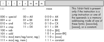
Figure 10-3: Basic Y86 instruction encoding
10.3.4.1 Eight Generic Y86 Instructions
As you can see in Figure 10-3, seven of the eight basic opcodes encode the or, and, cmp, sub , and add instructions, as well as both versions of the mov instruction. The eighth basic opcode is a special expansion opcode . This special instruction class provides a mechanism that allows us to expand the number of available instruction classes, which we will return to shortly.
To determine the full opcode for a particular instruction, you need only select the appropriate bits for the iii , rr , and mmm fields (identified in Figure 10-3). The rr field contains the destination register (except for the version of the mov instruction whose iii field is %111), and the mmm field encodes the source operand. For example, to encode the mov(bx,ax); instruction you would select iii = 110 (mov( reg , reg );) , rr = 00 (AX), and mmm = 001 (BX). This produces the 1-byte instruction %11000001 or $C0.
Some Y86 instructions are larger than one byte. To illustrate why this is necessary, take, for example, the instruction mov([1000],ax); , which loads the AX register with the value stored at memory location $1000. The encoding for the opcode is %11000110 or $C6. However, the encoding for the mov([2000],ax); instruction is also $C6. Clearly these two instructions do different things: one loads the AX register from memory location $1000, while the other loads the AX register from memory location $2000.
In order to differentiate between instructions that encode an address using the [ xxxx ] or [ xxxx +bx] addressing modes, or to encode a constant using the immediate addressing mode, you must append the 16-bit address or constant after the instruction's opcode. Within this 16-bit address or constant, the LO byte must follow the opcode in memory and the HO byte must follow the LO byte. So, the three byte encoding for mov([1000],ax); would be $C6, $00, $10, and the three byte encoding for mov([2000],ax); would be $C6, $00, $20.
10.3.4.2 Using the Special Expansion Opcode
The special opcode in Figure 10-3 allows the Y86 CPU to expand the set of available instructions that can be encoded using a single byte. This opcode handles several zero- and one-operand instructions, as shown in Figures 10-4 and 10-5.
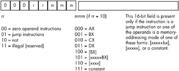
Figure 10-4: Single-operand instruction encodings (iii = %000)
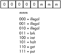
Figure 10-5: Zero-operand instruction encodings (iii = %000 and rr = %00)
There are four one-operand instruction classes whose encodings are shown in Figure 10-4. The first 2-bit encoding for the rr field, %00, further expands the instruction set by providing a way to encode the zero-operand instructions shown Figure 10-5. Five of these instructions are illegal instruction opcodes; the three valid opcodes are the halt instruction, which terminates program execution, the get instruction, which reads a hexadecimal value from the user and stores this value in the AX register, and the put instruction, which outputs the value in the AX register.
The second 2-bit encoding for the rr field, %01, is also part of an expansion opcode that provides all the Y86 jump instructions (see Figure 10-6). The third rr field encoding, %10, is for the not instruction. The fourth rr field encoding is currently unassigned . Any attempt to execute an opcode with an iii field encoding of %000 and an rr field encoding of %11 will halt the processor with an illegal instruction error. CPU designers often reserve unassigned opcodes like this one to allow themselves to extend the instruction set at a future date (as Intel did when moving from the 80286 processor to the 80386).
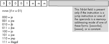
Figure 10-6: Jump instruction encodings
As shown in Figure 10-6, there are seven jump instructions in the Y86 instruction set and they all take the following form: j xx address ; . The jmp instruction copies the 16-bit address value that follows the opcode into the instruction pointer register, causing the CPU to fetch the next instruction from the target address of the jmp .
The jmp instruction is an example of an unconditional jump instruction. It always transfers control to the target address. The remaining six instructions - ja, jae, jb, jbe, je, and jne - are conditional jump instructions. They test some condition and only jump to the instruction's destination address if the condition is true; if the condition is false, these six instructions fall through to the next program instruction in memory. You would normally execute these conditional jump instructions immediately after a cmp instruction, as the cmp instruction sets the less than and equality flags that the conditional jump instructions test. Note that there are eight possible jump opcodes, but the Y86 uses only seven of them. The eighth opcode, %00001111, is another illegal opcode.
10.3.5 Examples of Encoding Y86 Instructions
Keep in mind that the Y86 processor fetches instructions as bit patterns from memory. It then decodes and executes those bit patterns. The processor does not execute instructions as strings of characters that are readable by humans , such as mov(ax,bx); . Instead, it executes the bit pattern $C1 in memory. Instructions like mov(ax,bx); and add(5,cx); are human-readable representations of instructions that must first be converted into binary representation, or machine code . In this section, we will explore this conversion.
10.3.5.1 The add Instruction
The first step in converting instructions to machine code is to choose an instruction to convert. We'll start with a very simple example, the add(cx,dx); instruction. Once you've chosen the instruction, you look up the instruction in one of the opcode figures from the previous section. The add instruction is in the first group (see Figure 10-3) and has an iii field of %101. The source operand is CX, so the mmm field is %010 and the destination operand is DX so the rr field is %11. Merging these bits produces the opcode %10111010 or $BA (see Figure 10-7).
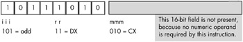
Figure 10-7: Encoding the add( cx, dx ); instruction
Now consider the add(5,ax); instruction. Because this instruction has an immediate source operand (a constant), the mmm field will be %111 (see Figure 10-3). The destination register operand is AX (%00), and the instruction class field is %101, so the full opcode becomes $10100111 or $A7. However, this does not complete the encoding of the instruction. We also have to include the 16-bit constant $0005 as part of the instruction. The binary encoding of the constant must immediately follow the opcode in memory, with the LO byte of the constant following the opcode, and the HObyte of the constant following its LO byte, because the bytes are arranged in little endian order. So the sequence of bytes in memory, from lowest address to highest address, is $A7, $05, $00 (see Figure 10-8).
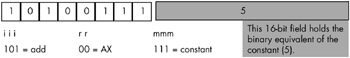
Figure 10-8: Encoding the add( 5, ax ); instruction
The add([2ff+bx],cx); instruction also contains a 16-bit constant that is the displacement portion of the indexed addressing mode. To encode this instruction, we use the following field values: iii = %101, rr = %10, and mmm = %101. This produces the opcode byte %10110101 or $B5. The complete instruction also requires the constant $2FF so the full instruction is the 3-byte sequence $B5, $FF, $02 (see Figure 10-9).
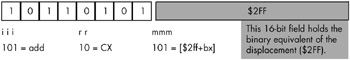
Figure 10-9: Encoding the add( [$2ff+bx], cx ); instruction
Now consider the add([1000],ax); instruction. This instruction adds the 16-bit contents of memory locations $1000 and $1001 to the value in the AX register. Once again, iii = %101 for the add instruction. The destination register is AX so rr = %00. Finally, the addressing mode is the displacement-only addressing mode, so mmm = %110. This forms the opcode %10100110, or $A6. The complete instruction is three bytes long because it must also encode the displacement (address) of the memory location in the two bytes following the opcode. Therefore, the complete 3-byte sequence is $A6, $00, $10 (see Figure 10-10).
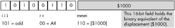
Figure 10-10: Encoding the add ( [1000], ax ); instruction
The last addressing mode to consider is the register indirect addressing mode, [bx]. The add([bx],bx); instruction uses the following encoded values: mmm = %101, rr = %01 (bx), and mmm = %100 ([bx]). Because the value in the BX register completely specifies the memory address, there is no need to attach a displacement field to the instruction's encoding. Hence, this instruction is only one byte long (see Figure 10-11).
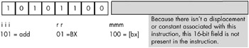
Figure 10-11: Encoding the add ( [bx], bx ); instruction
You use a similar approach to encode the sub, cmp, and , and or instructions. The only difference between encoding these instructions and the add instruction is the value you use for the iii field in the opcode.
10.3.5.2 The mov Instruction
The Y86 mov instruction is special, because it comes in two forms. The only difference between the encoding of the add instruction and the encoding of the mov instruction's first form ( iii = %110) is the iii field. This first form of mov copies either a constant or data from the register or memory address specified by the mmm field into the destination register specified by the rr field.
The second form of the mov instruction ( iii = %111) copies data from the source register specified by the rr field to a destination memory location that the mmm field specifies. In this second form of the mov instruction, the source and destination meanings of the rr and mmm fields are reversed so that rr is the source field and mmm is the destination field. Another difference between the two forms of mov is that in its second form, the mmm field may only contain the values %100 ([bx]), %101 ([disp+bx]), and %110 ([disp]). The destination values cannot be any of the registers encoded by mmm field values in the range %000..%011 or a constant encoded by an mmm field of %111. These encodings are illegal because the first form of the mov handles cases with a register destination, and because storing data into a constant doesn't make any sense.
10.3.5.3 The not Instruction
The not instruction is the only instruction with a single memory/register operand that the Y86 processor supports. The not instruction has the following syntax:
not( reg ); or not( address );
where address represents one of the memory addressing modes ([bx], [disp+bx], or [disp]). You may not specify a constant operand for the not instruction.
Because the not instruction has only a single operand, it needs only the mmm field to encode this operand. An iii field of %000 along with an rr field of %10 identifies the not instruction. In fact, whenever the iii field contains zero, the CPU knows that decoding beyond the iii field is necessary to identify the instruction. In this case, the rr field specifies whether we have encoded the not instruction or one of the other specially encoded instructions.
To encode an instruction like not(ax); , you would simply specify %000 for the iii field and %10 for the rr field. Then you would encode the mmm field the same way you would encode it for the add instruction. Because mmm = %000 for AX, the encoding of not(ax); would be %00010000 or $10 (see Figure 10-12).
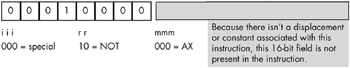
Figure 10-12: Encoding the not(AX); instruction
The not instruction does not allow an immediate, or constant, operand, so the opcode %00010111 ($17) is an illegal opcode.
10.3.5.4 The Jump Instructions
The Y86 jump instructions also use the special encoding, meaning that the iii field for jump instructions is always %000. These instructions are always three bytes long. The first byte, the opcode, specifies which jump instruction to execute and the next two bytes specify the address in memory to which the CPU transfers control (if the condition is met, in the case of the conditional jumps). There are seven different Y86 jump instructions, six conditional jumps , and one unconditional jump, jmp . All seven of these instructions set iii = %000 and rr = %01, and therefore only differ according to their mmm fields. The eighth possible opcode, with an mmm field value of %111, is an illegal opcode (see Figure 10-6).
Encoding these instructions is relatively straightforward. Picking the instruction you want to encode completely determines the opcode. The opcode values fall in the range $08..$0E ($0F is the illegal opcode).
The only field that requires some thought is the 16-bit operand that follows the opcode. This field holds the address of the target instruction to which the unconditional jump always transfers, and to which the conditional jumps transfer if the transfer condition is true. To properly encode this 16-bit operand you must know the address of the opcode byte of the target instruction. If you've already converted the target instruction to binary form and stored it into memory, you're all set - just specify the target instruction's address as the sole operand of the jump instruction. On the other hand, if you haven't yet written, converted, and placed the target instruction into memory, knowing its address would seem to require abit of divination. Fortunately, you can figure out the target address by computing the lengths of all the instructions between the current jump instruction you're encoding and the target instruction. Unfortunately, this is an arduous task.
The best way to go about calculating the distance is to write all your instructions down on paper, compute their lengths (which is easy, because all instructions are either one or three bytes long depending on whether they have a 16-bit operand), and then assign an appropriate address to each instruction. Once you've done this, you'll know the starting address for each instruction, and you can put target address operands into your jump instructions as you encode them.
10.3.5.5 The Zero-Operand Instructions
The remaining instructions, the zero-operand instructions, are the easiest to encode. Because they have no operands they are always one byte long. These instructions always have iii = %000 and rr = %00, and mmm specifies the particular instruction opcode (see Figure 10-5). Note that the Y86 CPU leaves five of these instructions undefined (so we can use these opcodes for future expansion).
10.3.6 Extending the Y86 Instruction Set
The Y86 CPU is a trivial CPU, suitable only for demonstrating how to encode machine instructions. However, like any good CPU, the Y86 design does provide the capability for expansion. Therefore, if you wanted to improve the CPU by adding new instructions, the Y86's instruction set will allow you to do it.
You can increase the number of instructions in a CPU's instruction set by using either undefined or illegal opcodes on the CPU. Because the Y86 CPU has several illegal and undefined opcodes, we can use them to expand the instruction set.
Using undefined opcodes to define new instructions works best when there are undefined bit patterns within an opcode group, and the new instruction you want to add falls into that same group. For example, the opcode %00011 mmm falls into the same group as the not instruction, which also has an iii field value of %000. If you decided that you really needed a neg (negate) instruction, using the %00011 mmm opcode makes sense because you'd probably expect the neg instruction to use the same syntax as the not instruction. Likewise, if you want to add a zero-operand instruction to the instruction set, there are five undefined zero-operand instructions in the Y86 instruction set for you to choose from (%0000000..%00000100, see Figure 10-5). You'd just appropriate one of these opcodes and assign your instruction to it.
Unfortunately, the Y86 CPU doesn't have many illegal opcodes available. For example, if you wanted to add the shl (shift left), shr (shift right), rol (rotate left), and ror (rotate right) instructions as single-operand instructions, there is insufficient space within the group of single-operand instruction opcodes to add these instructions (only %00011 mmm is currently open). Likewise, there are no two-operand opcodes open , so if you wanted to add an xor (exclusive OR) instruction or some other two-operand instruction, you'd be out of luck.
A common way to handle this dilemma, and one the Intel designers have employed, is to use one of the undefined opcodes as a prefix opcode byte. For example, the opcode $FF is illegal (it corresponds to a mov(dx,const); instruction), but we can use this byte as a special prefix byte to further expand the instruction set (see Figure 10-13). [3]
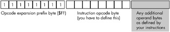
Figure 10-13: Using a prefix byte to extend the instruction set
Whenever the CPU encounters a prefix byte in memory, it reads and decodes the next byte in memory as the actual opcode. However, it does not treat thesecond byte as it would a standard opcode that did not come after a prefix byte. Instead, it allows the CPU designer to create a completely new opcode scheme, independent of the original instruction set. A single-expansion opcode byte allows the CPU designer to add up to 256 additional instructions to the instruction set. If the CPU designer wishes to add even more instructions, that designer can use additional illegal opcode bytes (in the original instruction set) to add yet more expansion opcodes, each with their own independent instruction sets, or the CPU designer can follow the opcode expansion prefix byte with a 2-byte opcode (yielding up to 65,536 new instructions) or any other scheme the CPU designer can dream up.
Of course, one big drawback to this opcode expansion scheme is that it increases the size of the new instructions by one byte, because each instruction now requires the prefix byte as part of the opcode. This also increases the cost of the circuitry (decoding prefix bytes and multiple instruction sets is fairly complex), so you don't want to use this scheme for the basic instruction set. Nevertheless, it does provide a good mechanism for expanding the instruction set when you've run out of opcodes.
[2] The Y86 processor only performs unsigned comparisons.
[3] We could also have used values $F7, $EF, and $E7 as they also correspond to an attempt to store a register into a constant. However, $FF is easier to decode. On the other hand, if you need even more prefix bytes for instruction expansion, you can use these three values as well.
EAN: 2147483647
Pages: 144