4.2 GPFS architecture
|
| < Day Day Up > |
|
4.2 GPFS architecture
This section describes the internal architecture, components, and technologies that make up GPFS.
4.2.1 GPFS components
GPFS is based on the following components:
-
A kernel extension
-
GPFS daemon
-
RSCT daemons
-
Portability layer module
Figure 4-1 shows these GPFS components.
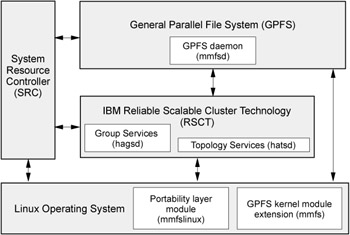
Figure 4-1: GPFS components
The GPFS kernel module extension (mmfs)
The kernel extension provides the interfaces to the virtual file system (VFS) for accessing a file system.
Structurally, applications issue file system calls to the operating system, which in turn presents the calls to the GPFS file system kernel extension. In this way GPFS appears to applications as just another file system. The GPFS kernel extension will either satisfy these requests using resources that are already available in the system, or send a message to the daemon to complete the request.
GPFS daemon (mmfsd)
The GPFS daemon performs all I/O and buffer management for GPFS including read-ahead for sequential read and write-behind for all writes not specified as synchronous. All I/O is protected by token management, which ensures data consistency of the systems.
GPFS daemon is a multi-threaded process with some threads dedicated to specific functions. This ensures that services requiring priority attention are not blocked because other threads are busy with routine work.
The daemon also communicates with instances of the daemon on other nodes to coordinate configuration changes, recovery, and parallel updates of the same data structures.
Specific functions that execute in the daemon include:
-
Allocation of disk space to new files and newly extended files.
-
Management of directories, including creation of new directories, insertion, and removal of entries into existing directories, and searching of directories that require I/O.
-
Allocation of appropriate locks to protect the integrity of data and metadata. Locks affecting data that may be accessed from multiple nodes require interaction with the token management function.
-
Disk I/O is initiated on threads of the daemon.
-
Security and quotas are also managed by the daemon in conjunction with the File System Manager.
RSCT daemons
Two RSCT daemons are used by GPFS to provide topology and group services. They are the hagsd and hatsd daemons.
The hagsd daemon relates to the Group Service subsystem. The function of the Group Services subsystem is to provide other subsystems with a distributed coordination, messaging, and synchronization.
The hatsd daemon relates to the Topology Service subsystem. The function of the Topology Services subsystem is to provide other subsystems with network adapter status, node connectivity information, and a reliable messaging service.
The daemons are added during the installation of the rsct.basic package.
For detailed information about RSCT daemon, refer to Appendix A, "SRC and RSCT" on page 253.
Portability layer module
To enable communication between the Linux kernel and the GPFS kernel modules, you must build a custom mmfslinux portability module based on your particular hardware platform and Linux distribution.
Before building the portability layer, check for the latest kernel level support in the GPFS for Linux Frequently Asked Questions at the following site:
http://www.ibm.com/servers/eserver/clusters/software/gpfs.html
and any applicable General Parallel File System (GPFS) Linux Kernel Patches, available at the following site:
http://www.ibm.com/developerworks/oss/linux/patches/
4.2.2 GPFS Network Shared Disk considerations
The NSD component gives GPFS the capability to access remote disks and global disk naming. The component is used in GPFS to virtualize the disks. Each disk in a GPFS cluster has a unique name and all GPFS commands, except the mmcrnsd command used to create the name, work with the NSD name.
The link between the NSD name and the physical disk is made transparent by GPFS. Depending on how the disks are attached to the cluster, the NSD component will be used differently. The following sections explain this in detail.
GPFS supports two types of disk connectivity:
-
NSD direct attached
-
NSD network attached
NSD direct attached
This model primarily relates to the use of Storage Area Networks (SANs) to provide direct access from multiple nodes to disks using Fibre Channel switches and adapters. Direct attached disks will achieve the best performance, because all servers will have a direct channel to the disks, as shown in Figure 4-2 on page 82.
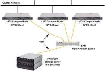
Figure 4-2: Direct attached disks
In this kind of configuration, the NSD component verifies that all of the nodes can see the shared disk and assigns a common name (for example, gpfs1nsd). This common name is later translated by GPFS to the appropriate local disk name on each node.
For example, some nodes may see the disk as /dev/sdb while other nodes see it as /dev/sdc. After the mmcrnsd command, all the nodes will be able to identify the shared disk with a single common name. So some nodes will assign the /dev/sdb device to the gpfs1nsd name while other nodes will assign the /dev/sdc device to the gpfs1nsd name. This scheme allows applications to work independently of the hardware configuration of each node.
The main advantage of using the direct attached disk configuration is that GPFS does not need to use the network to send data from one node to another. In this case, GPFS only uses the network to manage the metadata (see "Token management" on page 87) and provides high availability of the physical connections to the disks.
NSD network attached
NSD network attached is the second model supported by GPFS. In this model, each disk is connected to one (or two) servers, also known as NSD servers. Both user and GPFS control data flow through the Myrinet or Ethernet network. As shown in Figure 4-3 on page 84, network attached NSD can be used for high availability systems if the disks are defined with a primary and secondary servers. In this environment, if a primary server fails, the corresponding secondary server takes over the access to the disk and keeps the data available to the other nodes.
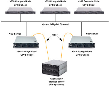
Figure 4-3: Primary and secondary servers
Compared to the direct attached configuration, only one or two nodes have direct access to a particular disk (primary and secondary nodes for the disk). When any other node needs to read or write to the disk, GPFS transfers the I/O request to the primary (or secondary) node, which will then write it directly to the disk.
The mmcrnsd command is used to provide a global name for the disk to give all GPFS daemons the new disk name (for example, gpfs1nsd) and access to this disk through the NSD server.
As the network in a NSD network attached environment is heavily used (for each read, write, or token request), a very high-speed network with low latency should be used for the best performance. Depending on the disk traffic, a Gigabit Ethernet, or Myrinet network is recommended. The network is used for token management and the data and metadata traffic. When a node wants to read or write a data block, it will ask the File System Manager for a token in the same way that it does for a direct attached configuration. After the token has been acquired, the node can send the read or write request to the primary server (the node that has physical access to the disk). After the completion of this task, the primary server sends an acknowledgement in the case of a write or the data in the case of a read operation.
| Restriction: | It is not possible to mix a direct attached configuration with a network shared disk configuration inside the same GPFS nodeset. |
4.2.3 GPFS global management functions
In general, GPFS performs the same functions on all nodes. It handles application requests on the node where the application exists. But, there are four special cases where nodes provide a more global function affecting the operation of multiple nodes in the GPFS cluster. These global functions reside on various nodes within the GPFS cluster/nodeset, as described here:
-
GPFS cluster data server (one or two per GPFS cluster)
-
GPFS configuration manager (one per nodeset)
-
Metanode (one per opened file)
-
GPFS file system manager (one per file system)
GPFS cluster data server
From the set of nodes included in your GPFS cluster, one node has to be designated as the primary GPFS cluster data server. GPFS configuration information is maintained on this node.
You can also (and we recommend that you do) specify a secondary GPFS cluster data server. Both the primary and the secondary GPFS cluster data server must be available when issuing GPFS administration commands.
GPFS cluster data server information is stored in a file that contains GPFS configuration and file system information. The GPFS cluster data is stored in the /var/mmfs/gen/mmsdrfs file. The master copy of all GPFS configuration information is kept on the primary GPFS cluster data server and secondary cluster data server, if you have one, and GPFS administrative commands constantly update mmsdrfs files in all nodes to keep them synchronized with the primary cluster data server and with the GPFS system files on each node in the nodeset.
Based on the information in the GPFS cluster data, the GPFS administrative commands generate and maintain a number of system files on each of the nodes in the GPFS cluster. These files are:
-
/var/mmfs/gen/mmsdrfs
Contains a local copy of the mmsdrfs file found on the primary and secondary GPFS cluster data server nodes.
-
/var/mmfs/etc/mmfs.cfg
Contains GPFS daemon startup parameters.
-
/etc/cluster.nodes
Contains a list of all nodes that belong to the local nodeset.
-
/etc/fstab
Contains lists for all GPFS file systems that exist in the nodeset.
-
/var/mmfs/gen/mmfsNodeData
Contains GPFS cluster data pertaining to the node.
-
/var/mmfs/etc/cluster.preferences
Contains a list of the nodes designated as file system manager nodes.
These files are constantly being updated by GPFS administrative commands and are not intended to be modified manually.
A GPFS cluster data server designation is created during the creation of a GPFS cluster, where you will specify at least one node as a primary GPFS cluster data server. Because the GPFS daemon relies on GPFS cluster data server accessibility to be able to start up and run GPFS administrative commands, we suggest that you specify a secondary GPFS cluster data server as a backup server. Commands that update the mmsdrfs file require that both primary and secondary GPFS cluster data server (if any) are accessible. And, when the GPFS daemon starts up, at least one of the two cluster data server nodes must be accessible. You may only specify two cluster data servers in one GPFS cluster nodeset. Example 4-1 shows the mmcrcluster syntax where you specify a primary and secondary GPFS cluster data server.
Example 4-1: GPFS cluster data server creation
mmcrcluster -t cltype -n NodeFile -p PrimaryServer [-s SecondaryServer] \ [-r RemoteShellCommand] [-R RemoteFileCopySommand]
Where:
| -p PrimaryServer | Specifies the primary GPFS cluster data server node used to store the GPFS cluster data. This node must be a member of the GPFS cluster. |
| -s SecondaryServer | Specifies the secondary GPFS cluster data server node used to store the GPFS cluster data. This node must be a member of the GPFS cluster. |
GPFS configuration manager node
The GPFS configuration manager node is the oldest continuously operating node in the nodeset. Its operation is monitored by Group Services and if it should fail for any reason, the next oldest node takes its place. There is only one configuration manager node per nodeset.
The GPFS configuration manager node task is to select the file system manager node and determines whether a quorum of nodes exist.
Metanode
The metanode is responsible for maintaining file metadata integrity. All nodes accessing a file can read and write data directly, but updates to metadata are written only by the metanode. In almost all cases, the node that has had the file open for the longest continuous period of time is the metanode. There is one metanode per open file.
GPFS file system manager node
The GPFS file system manager node handles the GPFS file systems being used by all the nodes of a GFPS cluster. The file system manager node is selected by the configuration manager node. If a file system manager node fails for any reason, a new one is selected by the configuration manager node and all functions continue without disruption, except for the time required to accomplish the takeover. There is one file system manager per file system that services all of the nodes using the file system.
You may list which node is currently assigned as the file system manager node by issuing the mmlsmgr command (see Example 4-2).
Example 4-2: A file system manager node list
[root@node001 /]# mmlsmgr file system manager node ---------------- ------------------ gpfs0 1 (storage001-myri0) [root@node001 /]#
The services provided by the file system manager include:
-
File system configuration
-
Management of disk space allocation
-
Token management
-
Quota management
File system configuration
It processes changes to the state or description of the file system, such as when:
-
Adding disks
-
Changing disk availability
-
Repairing the file system
The mount and unmount processing are performed on both the file system manager and the node requesting the service.
Management of disk space allocation
This service controls which regions of disks are allocated to each node, allowing effective parallel allocation of space.
Token management
The token management server coordinates access to files on shared disks by granting tokens that give the right to read or write the data or metadata of a file. This service ensures the consistency of the file system data and metadata when different nodes access the same file.
The token management function resides within the GPFS daemon on each node in the nodeset. For each mount point, there is a token management server, which is located at the file system manager.
Quota management
Quota management involves the allocation of disk blocks to the other nodes writing to the file system and comparison of the allocated space to quota limits at regular intervals. In a quota-enabled file system, the file system manager automatically assumes quota management responsibilities whenever the GPFS file system is mounted.
4.2.4 Disk storage used in GPFS
This section describes the storage technologies used by GPFS. There are two IBM TotalStorage Storage Servers that come as an option to IBM ![]() Cluster 1350. They are:
Cluster 1350. They are:
-
IBM TotalStorage FAStT200HA Storage Server
-
IBM TotalStorage FAStT700 Storage Server
The FAStT700 Storage Server requires either the EXP500 or the EXP700 storage enclosure.
The IBM TotalStorage FASt500 Storage Server is no longer an option to the IBM ![]() Cluster 1350.
Cluster 1350.
The following sections provide a brief overview of the IBM TotalStorage FAStT200HA and FAStT700 Storage Servers. For additional information about IBM storage solutions, refer to the following Web site:
http://www.storage.ibm.com/linux/index.html
IBM TotalStorage FAStT200HA Storage Servers
The IBM TotalStorage FAStT200HA Storage Server is a 3U rack-mountable device containing dual-active RAID controllers and space for up to 10 Fibre Channel (FC) hard disk drives. It targets the entry and midrange segment of the FC storage market. A typical use of the FAStT200HA is in a 2-node cluster environment with up to 10 Fibre Channel disk drives attached to the storage server. This is a cost-effective Fibre Channel RAID solution for environments where the highest level of availability and performance is not essential. It contains hot-swappable and redundant power supplies and fans.
If you need to connect more than 10 disks, you can use the EXP500 FC storage expansion enclosures. The FAStT200 supports up to 10 EXP500s. Each EXP500 can accommodate 10 additional disk drives, allowing a total of up to 110 disk drives. RAID levels 0, 1, 3, 5, and 10 are supported, and it includes a 256 MB battery-backed cache (128 MB per controller).
IBM TotalStorage FAStT700 Storage Server
The IBM TotalStorage FAStT700 Fibre Channel Storage Server is a high-performance unit that provides dual, redundant array of independent disks (RAID) controllers and Fibre Channel interfaces.
The FAStT700 Storage Server is based on the 2 Gb Fibre technology, allowing large amounts of data to be consolidated for quicker access and management.
The FAStT700 Storage Server supports 224 Fibre Channel hard drives. It also supports up to 20 FAStT EXP500 expansion units and up to 16 FAStT EXP700 expansion units. If the Fibre Channel drives are configured in a FAStT EXP500 expansion unit, a maximum of 220 drives are supported. If the configuration uses the FAStT EXP700 expansion unit, the maximum of 224 Fibre Channel hard drives is achieved.
The TotalStorage FAStT700 Storage Server is designed to be highly available, providing protection against component failures. Dual hot-swappable RAID controllers help provide high throughput and redundancy, and each controller supports 1 GB of battery-backed cache. Redundant fans, power supplies, and dynamic storage management further contribute to high availability to help reduce the risk downtime or the loss of data.
The TotalStorage FAStT700 Storage Server supports FlashCopy®, Dynamic Volume Expansion, and Remote Volume Mirroring with controller based support for up to 64 storage partitions. RAID levels 0, 1, 3, 5, and 10 configurations are also supported.
4.2.5 Data and metadata replication capability
The replication feature of GPFS allows you to determine how many copies of a file, metadata, or both to maintain. During file system creation, you can specify that you want all data, metadata, or both to be written twice.
When a GPFS file system had been created specifying replication for data and metadata, each time a block is written to the file system, it is duplicated somewhere else on the available disks used by the file system.
For example, suppose a file system called gpfs0 is created on two disks called gpfs1nsd and gpfs2nsd of 9 GB each. At the end of file system creation, the size of the gpfs0 file system will be 18 GB. If a file of 2 GB is copied onto this file system, because of the redundancy, the space available at the end of the write operation will be 18-2-2 = 14 GB.
The file system size does not automatically show itself as being half of its real size when replication is chosen. Though this might seem logical, it is not quite that simple. The metadata can be small or very large, depending on the size of the files stored in the file system. Therefore, it is difficult to estimate how much space will actually be used when the replication option is chosen.
Parameters can be used with the mmcrfs command to force GPFS to apply data, metadata, or data and metadata replication on different disks to avoid a single point of failure on a file system.
4.2.6 GPFS and applications
GPFS has been designed to support concurrent access for read and write on the same file, and to deliver maximum file system throughput.
Even if it is possible to use GPFS for different reasons, like high-availability solutions, it is important to be sure that the applications that will run in a GPFS cluster can take advantage of GPFS.
For example, it is impossible to use two Lotus® Domino® servers that access the same databases. You might want to do this for high-availability reasons, but when a Domino server is started on one node, it creates a locking file, which will prevent the other Domino server from starting. That means that even with a multiple nodes GPFS cluster, it is not possible to start more than one instance of a Domino server inside the same nodeset.
This example shows that despite having a file system that can support multiple access to the same file, the application needs to be "cluster" ready to take advantage of GPFS.
Usually, scientific applications that are developed specifically to run in a cluster environment can take advantage of GPFS, because these applications are designed to do concurrent accesses to the same file. These kinds of applications are those that typically run on High Performance Computing clusters.
Another possibility is to use GPFS for horizontal scaling and load balancing. As the file system is distributed over all the GPFS nodes, it is possible to run the same version of a Web server on all of the GPFS cluster nodes. This allows an update to a database that will be seen on all nodes as soon as a record has been inserted by one server.
To get better performance from a GPFS cluster, it is very important to know precisely how the disk subsystem and the applications are working. Creating a configuration with this knowledge in mind, GPFS can provide performance benefits compared to a simple file system.
4.2.7 Scenario and operation example
This section presents an example that describes a scenario based on a network shared disk configuration. Figure 4-4 on page 91 presents a scenario that has the following GPFS clusters characteristics:
-
The GPFS cluster has four nodes named Node1, Node2, Node3, and Node4.
-
One nodeset has been created in the GPFS cluster. The nodeset includes all nodes and is named nodeset1.
-
As the oldest online node in the nodeset is Node1, this node became the Configuration Manager for nodeset1.
-
The external disk connected to Node2, which makes it the storage node.
-
The external disk has been defined as a NSD. The NSD name of the external disk is gpfs1nsd and it has been passed to all the nodes in the GPFS cluster.
-
As all the nodes are online in the nodeset, the quorum is fulfilled.
-
A unique file system called gpfs0 has been created on the gpfs1nsd disk.
-
The Configuration Manager function of GPFS (Node1) chose Node3 as the File System Manager for the file system gpfs0.
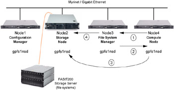
Figure 4-4: Example - Scenario and operation
How a GPFS write operation works
In this scenario, Node4 wants to write a block in a file that is physically located in Node2.
-
Node4 asks a write token to Node3 as the File System Manager for permission to write to this file.
-
Node3 gives a write token to Node4.
-
Node4 can now write its data to the file. The data actually gets put into a local buffer until an event asks the GPFS daemon to flush the buffer to disk. The data is sent to the storage node, Node2, which performs the physical write to the disks.
-
If the file that was written is now using more i-node blocks than before (in case of writing a bulk of data), the metadata for this file will be updated. Suppose that Node3 has that file open in longest continuous period, which makes it the metanode for this file; Node3 asks Node2 to write the modified metadata to the disk. All nodes now have access to the new data in the file.
|
| < Day Day Up > |
|
EAN: 2147483647
Pages: 123