Information Engineering
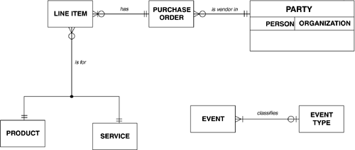
Information Engineering "Information engineering" was originally developed by Clive Finkelstein in Australia the late 1970's. He collaborated with James Martin to publicize it in the United States and Europe [Martin & Finkelstein, 1981], and then Martin went on from there to become predominantly associated with it [Martin & McClure, 1985]. Mr. Finkelstein later published his own version [Finkelstein, 1989; Finkelstein, 1992]. Because of the dual origin of the techniques, there are minor variations between Mr. Finkelstein's and Mr. Martin's notations The information-engineering version of our test case (with some of the notations from each version) is shown in Figure B.3. Figure B.3. An Information-Engineering Model. In the example, each PARTY is vendor in zero, one, or more PURCHASE ORDERS , each of which initially has zero, one or more LINE ITEMS , but eventually it must have at least one LINE ITEM . Each LINE ITEM , in turn , is for either exactly one PRODUCT or exactly one SERVICE . Also, each EVENT classifies zero or one EVENT TYPE , while each EVENT TYPE must be ( related to) one or more EVENTS Entity Types and AttributesMr. Finkelstein defines entity type in the designer's sense of representing "data to be stored for later reference" [Finkelstein, 1992, 23]. Mr. Martin, however, adopts the analyst's definition that "an entity type is something (real or abstract) about which we store data" [Martin & McClure, 1985, 249]. Entity types are shown in square-cornered rectangles. An entity type's name is inside its rectangle. Attributes are not shown at all. Mr. Finkelstein shows them in a separate document, the "entity type list". Mr. Martin has another modeling technique, called "bubble charts ", specifically for modeling attributes, keys, and other attribute characteristics. Names of entity types are common terms, and the words in multiword names are separated by spaces. RelationshipsRelationships are shown as solid lines between pairs of entity types, with symbols on each end to show cardinality and optionality. NamesMr. Martin names relationships with verbs, often only in one direction. Mr. Finkelstein doesn't name relationships at all. Cardinality/OptionalityEach relationship in information engineering has two halves , with each half described by one or more symbols. If an occurrence of the first entity type may or may not be related to occurrences of the second, a small open circle appears near the second entity type. If it must have at least one occurrence of the second, a short line crosses the relationship line instead. If an occurrence of the first entity type can be related to no more than one of the second entity type ("one and only one"), another short line crosses the relationship. If it can be related to more than one of the second entity type ("one or more"), a crow's foot is put at the intersection of the relationship and the second entity-type box. For example, in Figure B.3, a PARTY is vendor in zero, one, or more PURCHASE ORDERS . A PURCHASE ORDER , on the other hand, ( is to ) one and only one PARTY . Mr. Finkelstein has a unique notation, also shown in the figure. Note that each purchase order initially may have one or more line items, but eventually it must have at least one. That is, it is possible to create a purchase order without having to fill in the line items immediately, but at least one must be added later. The bar across the line between the circle and the crow's foot shows this. Unique IdentifiersUnique identifiers are not represented in an information-engineering data model. Mr. Martin shows them separately in "bubble diagrams". Sub-typesMr. Martin represents sub-types as nested boxes inside the super-type box. This is shown in the figure. Mr. Finkelstein portrays them as separate boxes, with a linked with "isa" relationship lines, as used in the Chen notation described above. Constraints between RelationshipsIn information-engineering notation, a constraint between relationships is shown by the relationship halves of the three (or more) entity types involved meeting at a small circle. If the circle is solid, the relationship between the relationships is "exclusive or " , meaning that each occurrence of the base entity type must (or may) be related to occurrences of one other entity type, but not more than one. This is shown in the figure, where each LINE ITEM is for either one PRODUCT or is for one SERVICE , but not both. If the circle is open, it is an "inclusive or" relationship, meaning that an occurrence of the base entity type must (or may) be related to occurrences of one, some, or all of the other entity types. CommentsInformation engineering is widely practiced. It is reasonably concise and attractive, consistent, and has a minimum of clutter. It is, however, missing important notations for attributes and unique identifiers, although some CASE tools have added these. Mr. Martin's approach to sub-types is compact and therefore desirable if models are to be presented to the nontechnical community, while Mr. Finkelstein's is not. Mr. Finkelstein's notation for "initially may be but eventually must be" is a very ingenious solution to a common modeling situation, not found in any other notation. |
| | |
| Team-Fly |
| Top |
EAN: 2147483647
Pages: 129

