ORM Constraints
Value Constraints
ORM constraints apply either to an object type or to one or more roles. This section discusses how to add constraints to an object type. The rest of the chapter explains how to add all the role-based constraints.
The previous chapter showed how to constrain the possible values for an object type by associating it with a data type. You can further constrain an object type by confining its possible values to a list or range of values within its data type. For example: SexCode = { ˜M , ˜F }; Score = {1..100}; SQLchar = { ˜a .. ˜z , ˜A .. ˜Z , ˜O .. ˜9 , ˜_ }. These are called value constraints because they limit the allowed values for a value type. If you apply a value constraint to an entity type, e.g. Sex(Code), the constraint is understood to apply to the associated value type, e.g. SexCode.
To add a value constraint to an object type, first ensure it is displayed it in the drawing window. Select or double-click the object type to bring up its Database Properties window. Open the Value pane by selecting Value from the list of categories. To add a value to the constraint, type the value in the Value field and press the Add button. The tool immediately displays the current list of values in braces next to the object type. If the data type is character-based, the tool adds single quotes around each value. Do not add quotes yourself. Figure 5-1 shows how it looks for the Sex object type if you already added the value ˜M and just typed in the value ˜F but have not yet added it.
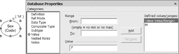
Figure 5-1: Half-way through adding an { ˜M , ˜F } value constraint to SexCode.
If you now press the Add button, the value list is updated to { ˜M , ˜F }, as shown in the lower left of Figure 5-2. To reposition a value constraint on the diagram, select the object type (not the constraint) and then move the control handle (small yellow diamond) that appears.
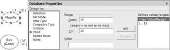
Figure 5-2: About to add a second range {14..20} to FloorNr.
Now consider an application domain where buildings must have fewer than 20 stories, and floors numbered 13 are excluded because some people think this number is unlucky. If FloorNr is the value type for floor numbers , you could assign it a numeric data type (e.g., smallint) and then add the value constraint {1..12, 14..20}. This constraint includes two ranges. Let's see how to add this constraint using the tool.
To add a range of values , type the minimum value in the From field, and the maximum value in the To field, and press the Add button. For example, Figure 5-2 shows how the Value pane looks after adding the first range 1..12. The second range 14..20 has been typed in but not yet added. If you now press the Add button, the value list is updated to {1..12, 14..20} as required.
To remove an entry from a value constraint , select the entry in the Defined values/ranges field, and press the Remove button. To delete a value constraint , remove each of its entries in this way.
By default, the drawing window displays at most five entries in a value constraint. For example, if you enter the seven values ˜Sunday through ˜Saturday for WeekDay, the first five values are shown, and an ellipsis " " is appended to indicate that other values are hidden (see Figure 5-3). To change the maximum number of values displayed for an individual object type , right-click the object type, choose Shape > Custom Properties from its context menu, and change the Value list size number in the Custom Properties dialog. This dialog can also be used to introduce new custom properties of your own. Regardless of how many values are displayed on the diagram, all the values you enter in the constraint are included for DDL generation purposes.
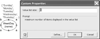
Figure 5-3: The maximum number of values displayed is editable in a custom property.
| Hint |
Declare a value constraint only if the list of values is stable. If the list of values is likely to change over time, store the values in a look-up table where they can be referenced and modified as needed. For example, if you want a one-column table of country codes, declare Country (Code) to be independent. If instead you want a two-column table of country codes and country names , use the fact type: Country (Code) has CountryNameO . |
Internal and External Uniqueness Constraints
The previous chapter showed how to use the Fact Editor to add uniqueness and mandatory role constraints to a single predicate. For these two kinds of internal constraint, the Fact Editor usually provides the easiest way to add the constraints. All other role-based constraints are best added and edited using the Add Constraint dialog . Although you can use the Fact Editor to add frequency and ring constraints, it's easier to add these with the Add Constraint dialog. Moreover, the Fact Editor can't be used for constraints that involve more than one predicate. From now on, all examples of ORM constraint editing will use the Add Constraint dialog.
You can quickly add constraints to predicates in the diagram window by selecting the relevant predicate(s) and invoking the Add Constraint dialog to add constraints to one or more of those predicates. To select more than one predicate, hold the Shift key down as you click each predicate. To invoke the Add Constraint dialog , right-click the selection and choose Add Constraints from the context menu (or choose Database > Add Constraint from the main menu).
For example, suppose you wish to add constraints to the following associations: Room is in Building; Room has RoomNr. Hold the Shift key down to select both the predicates. The selection is highlighted, as shown at the top of Figure 5-4. Now right-click, then select Add Constraints from the context menu. The Add Constraint dialog appears with the constraint type set to Uniqueness by default.
The roles of the selected predicates are displayed as role boxes, followed by the sentence type verbalization. The message field at the bottom of the dialog prompts you to click on the role boxes to select roles. To apply a uniqueness constraint to the first role of Room is in Building, click the first role box. The tool automatically highlights and numbers the selected role and verbalizes the constraint corresponding to this selection, as shown in Figure 5-4. To apply the constraint and leave the dialog open , press the Apply button. The constraint now appears on the diagram, and the role selection is cleared ready for the next constraint.
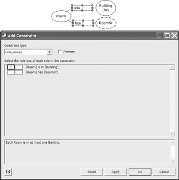
Figure 5-4: Adding a uniqueness constraint in the Add Constraint dialog.
If you press the OK button, the constraint is applied and the dialog closes . You can always clear the current role selection by pressing the Reset button. If you press the Cancel button, the selection is cleared and the dialog is closed.
With the dialog still open, apply a uniqueness constraint to the first role of the Room has RoomNr association by selecting its first role box and pressing Apply . By now, uniqueness constraints should be displayed on each of the two roles played by Room, as shown at the left of Figure 5-5. One more uniqueness constraint remains to be added. Here, the term "RoomNr" means a local room number used to identify a room within the scope of a single building. For instance, building 40 and building 41 might each have a room with room number 6767, but the BuildingNr-RoomNr combination 40-6767 refers to at most one Room, as does the combination 41-6767.
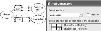
Figure 5-5: Adding an external uniqueness constraint spanning the right-hand roles.
To indicate that each BuildingNr-RoomNr combination refers to at most one room, add a uniqueness constraint that spans the roles played by Building and Room in these predicates. To do this, simply click both the roles in turn . The tool numbers these roles 1 and 2 as shown in Figure 5-5. The tool verbalizes the constraint automatically. This is an external uniqueness constraint because it spans roles from different predicates.
Press the OK button to apply the constraint and close the dialog. The external uniqueness constraint is displayed as a circled "U" connecting the two roles, as shown in Figure 5-6(a). If this constraint provides the primary way to identify Room, you may declare it primary by checking the Primary check box before pressing OK. Primary external uniqueness is displayed as a circled "P" as shown in Figure 5-6(b).
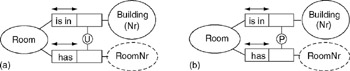
Figure 5-6: External uniqueness constraint (a) unqualified (b) primary.
To make an unqualified external uniqueness constraint primary, right-click the constraint, choose Database Properties from its context menu, and check the box labeled "Represents the primary identification scheme." If you do not declare a uniqueness constraint as primary and it is the only uniqueness constraint that is a candidate for primary reference, the tool will automatically mark it primary when building the logical database schema. To reposition an external uniqueness constraint on the diagram, simply select it and move it.
Although conceptually irrelevant, the order in which you specify the roles in an external uniqueness constraint determines the default sort order for any composite index defined over columns to which the constraint roles map in the logical schema. For this reason, it is usually better to select the roles in top-down order when specifying the constraint. In the Room example, this means you should select the Building role before the RoomNr role.
Simple and Disjunctive Mandatory Constraints
The ORM schema in Figure 5-7 is based on the Employee ORM source example that comes with the tool. In addition to five uniqueness constraints (four internal and one external), this schema includes three mandatory role constraints . A mandatory constraint on a single role is called a simple mandatory constraint, and is displayed as a black dot. A mandatory constraint on a set of two or more roles is called a disjunctive-mandatory constraint, or inclusive-or constraint and is displayed as a circled dot attached to the constrained roles.
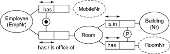
Figure 5-7: Simple and disjunctive mandatory role constraints.
The simple mandatory constraint on the first role of Room is in Building verbalizes as Each Room is in some Building. You already know how to add this constraint using the Fact Editor. You can also add a simple mandatory constraint in the Add Constraint dialog as follows . Right-click the predicate, choose Add Constraints from its context menu to invoke the Add Constraint dialog, select, Mandatory from the Constraint type drop-down list, and then select the role, as shown in Figure 5-8. Press Apply to apply the constraint and leave the dialog open , or press OK to apply the constraint and close the dialog.
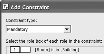
Figure 5-8: Adding the simple mandatory constraint: Each Room is in some Building.
The disjunctive-mandatory constraint in Figure 5-7 verbalizes as: Each Employee has some MobileNr or has some Room . For example, a contract employee might have a mobile number but not a room, and a permanent employee might have a room (and perhaps a mobile number too).
To add a disjunctive mandatory constraint , select its predicates (hold the Shift key down), right-click to open the context menu, select the Add Constraints option to invoke the Add Constraint dialog, select Mandatory from the Constraint type drop-down list, and then select the constrained roles. The selected roles are automatically numbered, as shown in Figure 5-9. Press Apply to apply the constraint and leave the dialog open, or press OK to apply the constraint and close the dialog. The constraint is displayed with a circled dot, as in Figure 5-7. To reposition an external uniqueness constraint on the diagram, simply select it and move it.
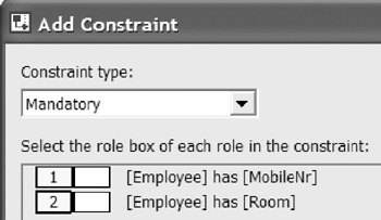
Figure 5-9: Adding a disjunctive-mandatory (inclusive-or) constraint.
| Caution |
If an object type has many simple mandatory role constraints, the mandatory dots may sometimes appear to connect to more than one role, leading to an ambiguous diagram. If you cannot solve this problem by repositioning the roles, then move the mandatory dot to the role instead of the object type. To do this for a given role, click the predicate twice to select the role, right-click to bring up the role's context menu, then check the Mandatory on role option. |
Constraint Editing and Deletion
Section 5.1 discussed how to edit or delete a value constraint. To edit or delete a constraint that applies to one or more predicates , select any of its predicates in the drawing window, open its Database Properties window, and select the Constraints pane. All the constraints that apply to that predicate are now displayed as icons along with the verbalization. For example, Figure 5-10 displays the two constraints that apply to the fact type Employee has Room .
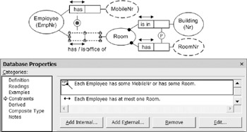
Figure 5-10: You may edit, remove, or add constraints in the database properties window.
To make minor edits to a constraint listed in the Constraints pane of the Database Properties window, select the constraint in the constraint listing, then press the Edit button to display its Constraint Properties dialog. Use the Notes pane of this dialog to add notes about the constraint . For some constraints, the dialog also has a Definition pane for simple edits (e.g., declaring a uniqueness constraint to be primary). For most constraints, you can also access the dialog by right-clicking the constraint shape and choosing Constraint Properties or Database Properties from its context menu.
To make major edits to an internal constraint, you may edit an internal constraint using the Fact Editor . To do so, right-click the predicate, select Fact Editor from its context menu, open the Constraints pane, and then make the desired changes. Another option is to delete the constraint and then add another constraint in its place.
To delete a constraint other than a value constraint, internal uniqueness constraint, or internal mandatory constraint, select the constraint shape and press the Delete key. You are now prompted "Remove selected item from the underlying model?" Press Yes to remove the constraint from the model and the diagram. Press No to remove it from the diagram only.
To delete a constraint listed in the Constraints pane of the Database Properties window, select the constraint in the constraint listing, then press the Remove button . To add an internal constraint to the predicate, press the Add Internal button to invoke the Add Constraint dialog and add the constraint there. To add an external constraint to the predicate, press the Add External button to invoke the Add Constraint dialog, and add the constraint there.
Set Comparison Constraints
If two roles are played by the same object type, or their object types share a common supertype , they are said to be compatible , and it is meaningful to compare their populations. The same is true for role-sequences (ordered lists of roles). For databases, only three set-comparison operators are relevant: subset ( ), equality (=) and mutual exclusion ( — ).
Subset Constraints
A subset constraint from a source role sequence to a target role sequence asserts that the population of the source role sequence must always be a subset of the population of the target role sequence. The constraint is displayed graphically as a circled " " connected by a dotted arrow running from the source to the target. The simplest case of a role sequence is just a single role. In Figure 5-11, the subset constraint means that the set of patients with a second given name must be a subset of the set of patients with a first given name. In other words, if a patient has a second given name, then he/she must also have a first given name.
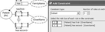
Figure 5-11: Adding a subset constraint between single roles.
To add this subset constraint , hold the Shift key down as you select the two predicates, right-click, and choose Add Constraints from the context menu. When the Add Constraint dialog appears, select Subset in the Constraint type field, and then select the source role for the constraint followed by the target role. As you select role boxes in the dialog, they are numbered 1, 2, etc. in the order of selection. If you do this correctly, the dialog box should now appear as in Figure 5-11. The constraint is automatically verbalized in the lower section of the dialog box. To apply the constraint and close the dialog, press OK . The subset constraint should now appear on the diagram as shown in Figure 5-11. To reposition the constraint, select it and move it as desired.
Figure 5-12 illustrates a subset constraint between role-pairs (each role-sequence contains two roles). If, as here, the roles in a pair are contiguous, the constraint connects to the junction of the roles. This constraint means that the population of Employee-Committee pairs instantiating the chairperson association must be a subset of the population of the membership association. That is, each person who chairs a committee must be a member of that very same committee.
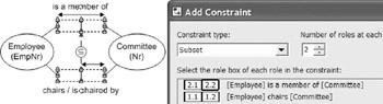
Figure 5-12: Adding a subset constraint between role-pairs.
To add this subset constraint, hold the Shift key down as you select the predicates, right-click, and choose Add Constraints from the right-click menu. When the Add Constraint dialog appears, select Subset in the Constraint type field. Notice that the lower section now prompts: If there is more than one role at each end of the constraint, increase the indicated "Number of roles at each end" to show this. By default, the number of roles at each end of the constraint is set to 1. Since there are two roles at each end of this constraint, change this setting to 2 (as in Figure 5-12). The label "Number of roles at each" should actually read "Number of roles at each end."
Now select the source role pair, and then the target role pair, ordering the roles within each pair to match their corresponding role from the other pair. As you select role boxes in the dialog, they are numbered 1.1, 1.2, 2.1, 2.2 in the order of selection. The first part of each number denotes the role sequence, and the second part denotes the position within that sequence. If you do this correctly, the dialog box should now appear as in Figure 5-12. The constraint is automatically verbalized in the lower section of the dialog box. Press OK to have the constraint accepted and added to the diagram.
Equality Constraints
An equality constraint between role sequences indicates their populations must always be equal. This is depicted as a circles "=" connected by a dotted line to the role sequences. To add this equality constraint , hold the Shift key down as you select both predicates, right-click, and choose Add Constraints from the right-click menu. When the Add Constraint dialog appears, select Equality in the Constraint type field, and then select the role sequences (in this example, each sequence has only one role). If you do this correctly, the dialog box should appear as in Figure 5-13.
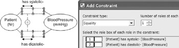
Figure 5-13: Adding a simple equality constraint between roles.
Actually, the order of the role-sequences in an equality constraint doesn't matter, since equality is symmetric (unlike subset). The constraint is verbalized in the lower section of the dialog box. Equality constraints between longer role sequences may be added in a similar way as for subset constraints.
Exclusion Constraints
An exclusion constraint between role sequences indicates their populations must always be disjoint ( mutually exclusive). This is depicted as a circled "X" connected by a dotted line to the role sequences. Figure 5-14 includes a pair-exclusion constraint (no person wrote and reviewed and the same book) and a simple exclusion constraint (no book can be both recommended and banned).
To quickly add these exclusion constraints, hold the Shift key down as you select all four predicates, right-click, and choose Add Constraints from the right-click menu. When the Add Constraint dialog appears, select Exclusion in the Constraint type field, and then select the recommended and banned roles (as in Figure 5-14). Now press Apply to have the constraint accepted and displayed, while leaving the dialog box open , ready to add the other exclusion constraint.
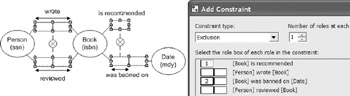
Figure 5-14: Adding a simple exclusion constraint.
Now select Exclusion in the Constraint type field, increment the number of roles at each end to 2, and then select the role pairs in the writing and review fact types (as in Figure 5-15). Now press OK to apply the constraint and exit the dialog.
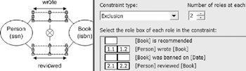
Figure 5-15: Adding a pair-exclusion constraint.
Exclusive or Constraints
In ORM, an exclusive-or constraint is simply an orthogonal combination of an inclusive-or (disjunctive mandatory) constraint and an exclusion constraint. By default, these two constraints are overlaid, as shown in Figure 5-16(a), where superimposing a circled dot (disjunctive mandatory) and circled "X" (exclusion) results in a lifebuoy symbol. To create this example, add the two fact types to the diagram window, select them, right click to bring up the Add Constraint dialog, and add first one constraint and then the other to the same roles (press Apply after adding the first constraint, and OK after the second constraint).
If you wish to visually separate the two constraints making up the inclusive-or constraint, right-click on the lifebuoy symbol and chose the option Split X/OR constraint. The constraints will be now displayed separately as in Figure 5-16(b). You can now work with either constraint individually. For example, you could delete just one of them by selecting it and pressing Delete . If the two constraints appear separately, you can merge them into the lifebuoy symbol, by selecting one of the constraints and dragging it over the other.
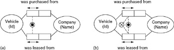
Figure 5-16: Exclusive-or is inclusive-or plus exclusion.
Subtyping
If the population of an object type A must always be a subset of the population of another object type B , then A is said to be a subtype of B , and B is said to be a supertype of A . In ORM, this is depicted visually by a solid arrow running from the subtype to the supertype. For example, Figure 5-17 shows a fragment of a model used for a hospital information system. In this model, MalePatient and FemalePatient are each subtypes of Patient.
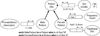
Figure 5-17: MalePatient and FemalePatient are subtypes of Patient.
The main reason for introducing a subtype is to declare that specific roles are played only by that type. For example: prostate status may be recorded only for male patients ; pregnancy counts and pap smear results are recorded only for female patients. Hence subtyping provides another kind of constraint .
Other reasons for subtyping are to encourage reuse of supertypes, and to display a type taxonomy. Currently, the Visio ORM source model solution does not allow subtypes to be introduced purely for taxonomy reasons (i.e., merely to show a classification scheme). So each subtype must play at least one specific role.
To add a subtype connection , first ensure that the object types that are to play as subtype and supertype appear on the same page of the drawing window (e.g., declare them in the Business Rules window, and then drag them onto the drawing window). Now drag the Subtype Relationship arrow from the ORM stencil onto the drawing window. Drag the end of this arrow into the center of the subtype until it is framed by a red rectangle, and then release the mouse button. The end of the arrow should now be glued to the subtype ellipse, as shown by a small red box at its end. Now drag the arrow tip to the center of the supertype until it is framed by a red rectangle, then release the mouse button. The tip of the arrow should now be glued to the subtype ellipse. Figure 5-18 shows the subtype arrow glued to MalePatient and Patient.
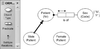
Figure 5-18: Adding a subtype connection.
By default, a subtype inherits the reference scheme of its supertype, so there is no need to add a reference scheme for the subtype, except in rare cases where the reference scheme varies with different contexts. For a discussion of context-dependent reference, see Chapter 6 of Halpin (2001).
In strict ORM, each subtype must have a formal subtype definition, enabling membership in the subtype to be determined by properties of its supertype(s). For example, Figure 5-17 includes the subtype definitions: each MalePatient is a Patient who is of Sex ˜M ; each FemalePatient is a Patient who is of Sex ˜F . Given this definition, and the value constraint { ˜M , ˜F } on Sex, the subtypes must be collectively exhaustive (their union is equal to their supertype). Given the subtype definition, and the uniqueness constraint ( each Patient is of at most one Sex ), the subtypes must be mutually exclusive.
So the subtypes form a partition of the supertype. In ORM, this implied partition constraint may be displayed as an xor-constraint between the supertype ends of the subtype connections (see circled X and mandatory dot in Figure 5-19). This notation is used because the xor constraint applies to roles in virtual predicates underlying the subtype connections.
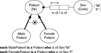
Figure 5-19: In principle, the subtype partition constraint is implied.
This implied subtyping constraint approach enables far richer subtyping support than other approaches provide. Subtype definitions of arbitrary complexity may be expressed as queries in a formal ORM language such as ConQuer, enabling automatic generation of DDL code to enforce the constraints at the database level. This goes far beyond simple foreign key clauses and completeness and disjointness checks. For more details on this, see sections 6.5, 10.3, and 10.4 of Halpin (2001).
In practice, however, the Visio ORM tool does not yet support formal subtype definitions, or the automated display of implied exhaustion and exclusion constraints between subtype connections, or the full DDL code generation capabilities to map formal subtype definitions. Even without this support, it is good practice to add subtype definitions as comments in the Database Properties sheet for the subtype. For example, to add a subtype definition for MalePatient, double-click that object type to bring up its properties sheet, select the Subtype category to bring up the Subtype pane, and then enter the definition in the Subtype definition field, as shown in Figure 5-20.
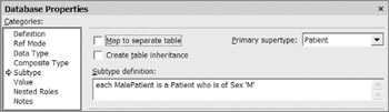
Figure 5-20: Adding a subtype definition.
You can phrase the subtype definition in any way you like, because it is treated simply as a comment. If you do not enter a definition for each subtype, the tool issues a warning about this when a model error check is invoked (either directly or during a build). These subtype definitions are included in the automated verbalization, but do not appear on the diagram. To display a subtype definition on the diagram, use Visio's standard Text Tool to open a text box, and then copy the definition into that. This is how the definitions were included them in the figures above.
If you want to display exhaustion and exclusion constraints between subtype connections, as in Figure 5-19, you need to do this manually using other Visio shapes and connectors. You can use the rich diagramming power of Visio to add as many adornments as you to like to the model diagrams. This is very useful for documentation purposes. However any such annotations are ignored when a relational model is built from the underlying ORM source model, or when physical DDL code is generated.
The Subtype properties pane includes a list box for the primary supertype (see Figure 5-20). The primary supertype provides the default reference scheme for the subtype. If a subtype has only one supertype, this is its primary supertype. If a subtype has more than one supertype, one of these must be chosen as its primary supertype. For example, the ORM schema in Figure 5-21 exhibits multiple inheritance, because FemaleInPatient has two supertypes. To choose the primary supertype, first select the subtype, then choose the relevant option from the Primary supertype drop-down list box. The tool displays the primary supertype connection as a solid arrow, and other supertype connections as a broken arrow. In Figure 5-21, FemalePatient is the primary supertype of FemaleInPatient, and InPatient is its other supertype.
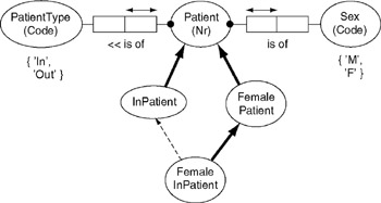
Figure 5-21: FemalePatient is the primary supertype of FemaleInPatient.
In addition to the subtype definition field and primary supertype list box, the Subtype properties pane includes and check boxes for table mapping and inheritance (see Figure 5-20). The check box options do not relate to the conceptual level at all. Instead they are used to control how subtype specific details are mapped to a relational database schema. These options are discussed in detail in Chapter 7.
To delete a subtype connection , select the subtype arrow, then press the Delete key. Answer Yes when prompted to remove it from the underlying model. If you answer No, the arrow is removed from the diagram, but the subtype relationship remains in the model. To redisplay hidden subtype connections, right-click the subtype, then select Show Relationships from its context menu. However, this will display all the relationships in which the subtype plays, not just its subtype relationships.
Frequency Constraints
In ORM, an occurrence frequency constraint declares how many times an entry may occur in the population of a role, or role combination. The number of times may be a simple integer (e.g., 2), a bounded range (e.g., 2.5) or an unbounded range (e.g., >=2).
Consider the ORM model in Figure 5-22. Here each patient is allocated to at most one test group . The ">= 5" frequency constraint next to the role played by TestGroup means that any test group that does play this role must do so at least 5 times. If you populate this fact type, each entry in the TestGroup column must appear there at least 5 times. So, non-empty test groups must include at least five patients . Be careful in choosing the role(s) to which the constraint applies. If in doubt, populate the relevant fact types to clarify the meaning of the constraint.
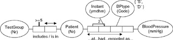
Figure 5-22: Simple and compound frequency constraints.
The quaternary fact type in Figure 5-22 is used to maintain a history of patients' blood pressure readings. BPtype (Blood pressure type) is identified by a code (D = Diastolic, S = Systolic). The "2" frequency constraint besides the role connector linking roles played by Patient and Instant indicates that any given (patient, instant) pair that populates that role pair does so exactly 2 times. In the context of the 3-role uniqueness constraint and the { ˜D , ˜S } value constraint on BPtype, this ensures that any time a patient has his/her BP recorded, both diastolic and systolic readings must be recorded.
To add frequency constraints to predicates, use either the Add Constraint dialog or the Advanced pane of the Fact Editor. The following discussion shows how to use the Add Constraint dialog to enter the two frequency constraints in Figure 5-22.
Hold the shift key down as you select both predicates, then right-click, and choose Add Constraints from the context menu. The Add Constraints dialog appears with both predicates included, as shown in Figure 5-23. To add the first frequency constraint (each test group has at least 5 patients), choose Frequency as the Constraint type , select the TestGroup role, set the Minimum frequency to 5, and delete any entry in the Maximum frequency box (no entry here means no upper limit).
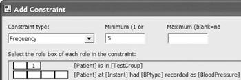
Figure 5-23: Adding the frequency constraint that each test group includes at least 5 patients.
Take care to select the correct role ”in this example, the predicate is displayed in reverse order to that shown on the diagram. Read the constraint verbalization to ensure this is consistent with your intention , and press the Apply button. The tool now displays ">=5" next to the relevant role on the ORM diagram and resets the entries in the Add Dialog window.
To add the frequency constraint on the quaternary predicate, choose Frequency as the Constraint type , select the Patient and Instant roles, and then set both the Minimum frequency and Maximum frequency to 2, as shown in Figure 5-24. Check the verbalization and then press OK to apply the constraint and exit the dialog. A "2" should now appear next to the Patient-Instant role connector as shown in Figure 5-22. If desired, you can reposition things by using standard Visio controls (e.g., use Flip Vertical on the predicate to move its uniqueness constraint to the other side, and select and drag relevant constraints and predicate text).

Figure 5-24: Constraint: each Patient-Instant pair in the quaternary fact table is there twice.
Ring Constraints
In some universities, it is common practice for an academic to be monitored by another academic. Monitoring involved attending a lecture by the other academic, and giving him/her feedback on how to improve it. Although each academic has at most one monitor, it is possible for the same academic to monitor many other academics . This monitoring relationship is modeled as an n:1 binary fact type in the simple ORM model shown in Figure 5-25.
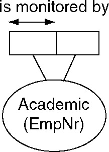
Figure 5-25: The monitoring association is a ring fact type.
Notice that both roles in the is-monitored-by predicate are played by the same object type, Academic. The fact type path goes from the object type through the role pair and back to the object type, forming a ring. For this reason, the fact type Academic is monitored by Academic is called a ring fact type . Since both roles are played by the same object type, it is meaningful to compare instances in their populations, and the roles are said to be compatible .
In practice, most ring fact types need further constraints on how their role instances may be logically related . Such constraints are called ring constraints . See if you can think of some constraint that needs to be added to the monitor fact type, before reading on.
As you may have guessed, we should at least require that no academic is monitored by himself/herself. Technically this is said to be an irreflexive ring constraint, and is denoted by the symbol " o ir " besides the two roles involved, as shown in Figure 5-26. The " o " suggests a ring, and the " ir " is short for "irreflexive".
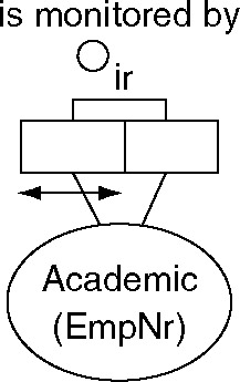
Figure 5-26: The irreflexive constraint declares that no academic monitors himself/herself.
To add a ring constraint to a predicate, you can use either the Add Constraint dialog or the Constraints pane of the Fact Editor. Note: If the constrained roles are played by different but compatible object types (e.g., a subtype and its supertype ) then you must use the Add Constraint dialog, not the Fact Editor. The following discussion shows how to add the ring constraint in Figure 5-26 using the Add Constraint dialog, assuming the fact type is already displayed in the drawing window.
Right-click the monitor predicate, and select Add Constraints from the context menu to bring up the Add Constraint dialog. Now choose Ring from the Constraint type field, and click the two roles in the displayed predicate (see Figure 5-27).
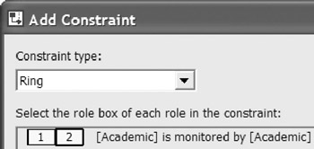
Figure 5-27: Selecting the roles for a ring constraint.
As you select the two roles, they are automatically numbered 1 and 2, and the Ring Constraint Properties dialog appears, with the mouse cursor appearing as a cross-hair. Move this cursor to select the ellipse marked ir (irreflexive), which sets the constraint's Ring Type to Irreflexive (see Figure 5-28).
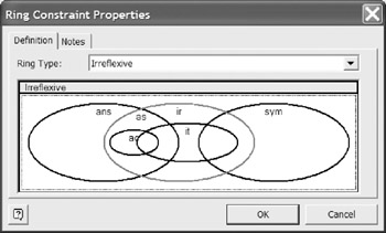
Figure 5-28: Choosing the specific type of ring constraint.
Press the OK button to apply this choice and close the properties dialog. The Add Constraint dialog now displays the constraint verbalization as ˜ No Academic is monitored by itself . If you would rather see the verbalization at the same time as you move the cross-hair cursor over the constraint selector, you can alternatively enter ring constraints directly via the Fact Editor.
Press OK in the Add Constraint dialog to apply the constraint and exit the dialog. The ring constraint now appears on the diagram, as shown in Figure 5-26. You can finesse the diagram by using standard Visio controls (use Flip Vertical on the predicate to move its uniqueness constraint to the other side, then select and drag the predicate text). As usual, you can see the verbalization of all constraints on the predicate by selecting it and opening the Verbalizer.
A ring constraint may apply only to a pair of roles played by the same (or a compatible) object type. The role pair may form a binary predicate or be embedded in a longer predicate. Let R be the relation type comprising the role pair. Using "iff" for "if and only if", "~" for "not" and " ’ " for "implies," we say that R is irreflexive iff for all x , ~ xRx . This is denoted by connecting the role pair to the constraint symbol " o ir ".
As shown in Figure 5-28, you may specify six kinds of ring constraint. The other five may be summarized as follows . R is symmetric iff for all x , y , xRy ’ yRx . Symmetry is used more often for derivation, but if used as a constraint, it is denoted by connecting the role pair to " o sym ". R is asymmetric ( o as ) iff for all x , y , xRy ’ ~ yRx . R is antisymmetric ( o ans ) iff for all x, y, x ‰ y & xRy ’ ~yRx . R is intransitive ( o it ) iff for all x, y, z, xRy & yRz ’ ~xRz . Asymmetry and intransitivity each imply irreflexivity. Exclusion implies asymmetry (and irreflexivity). An irreflexive, functional relation must be intransitive. One very expensive ring constraint to enforce is acyclicity ( o ac ), i.e., no cycles are permitted by using the relationship type one or more times. For further explanation of these concepts, see section 7.3 of Halpin (2001).
Although the Euler diagram in Figure 5-28 may appear complex, it actually simplifies things by avoiding incompatible or redundant ring constraints. For example, if you choose Asymmetric, the tool won't let you choose Irreflexive as well because this is implied by asymmetry. For the monitoring relationship discussed earlier, it is possible for two academics to monitor each other, so this is a simple case of irreflexivity, not asymmetry.
More than one atomic ring constraint may apply to the same predicate. For example, the fact type Person is parent of Person in Figure 5-29 is declared to be both asymmetric (as) and intransitive (it). The tool treats this as a single, composite ring constraint, as indicated by bracketing the two components (as, it). To add this constraint, use the Add Constraint dialog as before and position the cross-hair cursor to obtain the ˜Asymmetric + Intransitive option.
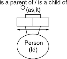
Figure 5-29: The parenthood association is asymmetric and intransitive.
To facilitate checking of incompatible or duplicate ring constraints, the tool relies on the Euler diagram interface for ring constraints, allowing only one ring constraint (simple or composite) per predicate. So if you previously added one ring constraint to a predicate, and wish to add a second one to it, you need to edit the original constraint, replacing it with the composite constraint. To edit an existing constraint on a single predicate, select the predicate to invoke its Database Properties sheet, choose the Constraints category, select the constraint, and then press the Edit button.
The tool verbalizes the asymmetric and intransitive constraints as shown below. The intransitive constraint assumes that parenthood is restricted to genetic parenthood and that no incest is allowed. In reality, the parenthood relation is not just asymmetric, but acyclic . Acyclicity constraints involve recursion, and may be expensive to enforce. For details of how the tool maps ring constraints to DDL code, see section 7.5.
Indexes
Just as an index to a book enables you to quickly find a topic of interest, indexes on database columns enable the database system to quickly access entries for those columns . Being a performance issue, indexes relate to the physical level rather than the conceptual level. However you may annotate roles in an ORM schema with index markers to declare facts you want efficient access to in the physical implementation.
An index marker is displayed as a circled "I" attached to the role(s) it impacts. For example, Figure 5-30 includes indexes to provide efficient access to a patient's family name and birth country. Most DBMSs automatically create unique indexes on primary keys and columns with unique constraints, so there is normally no need to add an index to a role if it has a simple uniqueness constraint.
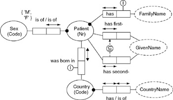
Figure 5-30: An index appears as a circled "I" attached to the role(s) it constraints.
An index on family name makes sense if you often want to access a patient's details without having to specify their patient number, but rather by entering a family name to list all patients with that name.
To add an index to one or more roles, right-click the predicate(s) and choose Add Constraints to open the Add Constraint dialog. Then choose Index as the Constraint type , select the role(s), then press OK to apply the constraint and exit the dialog (or press Apply to apply the constraint without exiting the dialog).
For example, to add an index for a patient's family name, make the selection shown in Figure 5-31. The message field at the bottom of the dialog will advise that a nonunique index will be created over the role played by Familyname. When the model is mapped to a relational schema, a non-unique index will be created over the column(s) to which that role maps. Since many people may have the same family name, the index will be non-unique. Hit the OK button to apply the index and exit the dialog. An index marker now appears as a circled "I" on the ORM model, attached to the family name role, as shown in Figure 5-30. Although stored with the ORM model, this physical annotation is not part of the pure conceptual schema.
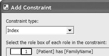
Figure 5-31: Adding an index marker to the role played by FamilyName.
In Figure 5-30, another index is applied to the role played by Country in the association Person was born in Country . If you often want to inquire about where a person was born, and you want the name of the country, not just the country-code, when you make such a query, then this entails a frequent conceptual join operation between the two roles played by Country. These roles map to separate tables, one role mapping to a foreign key and the other to its referenced primary key. At the relational level, this means we have a need to efficiently join the tables by matching the foreign and primary key values. In this case, you can add an index on the birth-country role by clicking on its fact type and using the Add Constraint dialog.
Non-uniqueness indexes are sometimes over-used. In most cases, an index should be applied only after an analysis of the focused transactions for the application reveals a performance need for it.
Indexes can also be specified directly on a logical model. Examples of DDL code generated to enforce indexes are discussed in Chapter 7.
Constraint Layers
One of ORM's strengths is its richly expressive constraint notation. When specifying detailed requirements, it's often helpful to visualize the relevant business rules graphically. However, there may be times when you wish to ignore the fine details. One way to do this is to use constraint layers to control which kinds of constraints are displayed on screen and/or printed. In the ORM Source model solution, constraint layers are implemented using Visio's standard layer properties mechanism.
For example, the ORM model in Figure 5-30 displays five kinds of constraints: simple mandatory, internal uniqueness, value, subset, and index. Simple mandatory and internal uniqueness constraints are stored as part of the predicate shape, so are always displayed. But you can suppress the display of all other kinds of ORM constraints by controlling the layer properties settings for the diagram. To access the Layer Properties dialog, choose View > Layer Properties from the main menu. The dialog for our current model is shown Figure 5-32.
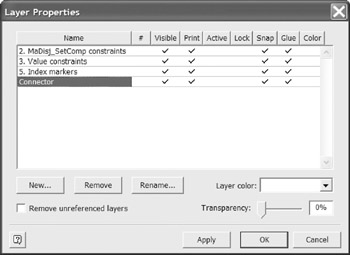
Figure 5-32: Constraint layers allow most kinds of constraints to be hidden.
Different kinds of constraint exist on different layers. In addition to the alwaysshown constraints (simple mandatory and internal uniqueness), this model has constraints on layers 2, 3, and 5. Layer 2 shows disjunctive mandatory (inclusive-or) and set-comparison (subset, equality, exclusion) constraints. Layer 3 shows value constraints. Layer 5 shows index markers.
To suppress display on screen of a constraint layer , click the check mark in the Visible column in this dialog (this removes the check mark), then press the Apply button. If you remove all check marks for Visible in this example, Figure 5-30 will be redisplayed without value, subset, and index constraints. The diagram will still print as Figure 5-30 unless you uncheck the entries in the Print column. The column entries are toggles, so you can restore a check mark to a cell simply by clicking it. ORM models may include other kinds of constraint that exist on other layers.
With the exception of simple mandatory and internal uniqueness constraints, ORM constraints are partitioned into five layers, as shown in Figure 5-33. Each layer can be individually controlled.
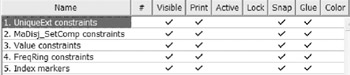
Figure 5-33: Five layers of constraints may be suppressed.
Layer 1 includes external uniqueness constraints. Layer 2 includes disjunctive-mandatory (inclusive-or) and set comparison (subset, equality, exclusion) constraints. Since exclusive-or constraints are simply combinations of inclusive-or and exclusion constraints, these are included on layer 2. Layer 3 holds value constraints. Layer 4 displays frequency and ring constraints. Finally, layer 5 is used for indexes. By default, all constraints are displayed and printed, unless their display/print setting is unchecked.
Overview of Database Modeling and the Database Modeling Tool
The Conceptual Modeling Solution (ORM)
- Object Types, Predicates, and Basic Constraints
- ORM Constraints
- Configuring, Manipulating, and Reusing ORM Models
- Mapping ORM Models to Logical Database Models
- Reverse Engineering and Importing to ORM
- Conceptual Model Reports
The Logical Modeling Solution (ER and Relational)
- Creating a Basic Logical Database Model
- Generating a Physical Database Schema
- Editing Logical Models”Intermediate Aspects
- Editing Logical Models”Advanced Aspects
- Reverse Engineering Physical Schemas to Logical Models
- Logical Database Model Reports
Managing Database Projects
EAN: 2147483647
Pages: 150
- Key #3: Work Together for Maximum Gain
- Beyond the Basics: The Five Laws of Lean Six Sigma
- When Companies Start Using Lean Six Sigma
- Making Improvements That Last: An Illustrated Guide to DMAIC and the Lean Six Sigma Toolkit
- The Experience of Making Improvements: What Its Like to Work on Lean Six Sigma Projects
