Advanced Design Strategies
|
Up to this point, the discussion of design has been directed at the access path design and the methods of securing access to the internal network from the external network. In most cases, the DMZ is used to block incoming traffic and control it more completely through the multiple layers that are placed in the design, thus offering tighter control that stops access to the internal network. Standard DMZ designs almost always default to a condition in which the internal network's access to the external public network is unrestricted.
Before we finish our discussion of basic designs, it is appropriate to explore briefly some of the ways we might consider blocking access from the internal network to the external network, either wholly or in part, if the security design we created earlier indicates a need to do so. In the next section, we visit some of the common conditions that your organization might want to block or limit in your efforts to protect your assets and information.
Advanced DMZ Design Concepts
Intranet users have often been allowed full and unrestricted access to public network resources via the DMZ structure. Often, the protection for the internal network involves using NAT or some proxied connectivity to allow outward flow while restricting inbound flow to requests originated within the internal network. You should think about some special considerations while you are working in this area. Let's list some of them and consider them as an addition to the overall design:
-
General FTP use that is unrestricted may lead to security breach. Outbound FTP should not be allowed from the internal network.
-
DMZ design lends itself to allowing control of unnecessary services that may be present on the external network. For example, the DMZ design may incorporate outbound blocking of ports to services providing instant messaging, nonbusiness-related networks, and other restrictions as appropriate to your system.
-
Known management ports for externally located devices and services should be blocked from the internal network.
Additionally, we must look at the applications that are in use from the internal network to determine the appropriate level of outbound access to accommodate those applications. When you're given the task of building a DMZ in a large DMZ environment or when you need to support multiple service types, it might be desirable to separate them by adding additional "legs" to the DMZ. There are two reasons why you might want to use a DMZ leg:
-
An additional leg might be necessary if the number of servers has exceeded the number of available IP addresses for hosts on the DMZ subnet. By adding a DMZ interface, you can assign another IP range and add more servers.
-
It's a good idea to separate service types. Service types are Web, FTP, e-mail, DNS, VPN, and remote access.
As we continue, a number of other considerations must be taken into account as we create the design plan. For example, although many DMZ configurations are allowing access to a Web server that we are operating, there must be a method in place to advise us of the presence of potential hackers working within our borders.
To this end, the DMZ design will also most often create a provision for some type of IDS system placement in the various levels of the DMZ structure to evaluate and report on intrusion attempts. As with all services that we provide, the Web services servers must be continually evaluated and kept up to date in their levels of security and service packs.
Another conceptual area that must be visited is the difference between a DMZ that is established for the purpose of isolating or segregating the public network from your private network, and a DMZ that is used for the purpose of isolating or segregating a portion of your internal network. The design you create should include the capability to establish internal DMZ structures to protect confidential information from the general LAN operation. This could include segregation of financials or provision for VPN access to the internal network that does not originate from the public network (such as Frame Relay PVC channels or PSTN modem access). Again, when dealing with these special cases, the designer must make sure that the design does not introduce a back-door situation that allows public network bypass of the DMZ structure through compromise of a host machine.
Remote Administration Concepts
Remote management and administration of the various pieces of hardware within the DMZ design you implement provide another challenge for the designer. Although it is extremely tempting to use the built-in capabilities of the various operating systems and the management software provided for many of our hardware devices, it is very important to give the alternatives a good long look. Use of these tools for normal management from within the internal network is almost certainly a quick recipe for breach and disaster.
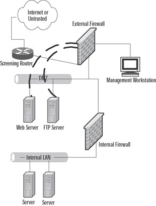
It is certainly technologically possible to access the equipment in the DMZ through use of SSH, Telnet, or Microsoft's Terminal Services and to create firewall rules allowing traffic on the necessary ports to accomplish this task. So, what's the problem with using the built-in tools? In-band versus out-of-band management of your systems is the problem we need to work on. In-band management tools, including SNMP-based traps and management agents, rely on the integrity of the network they are mounted on to provide the reports and management capabilities we use to control the various hardware and configuration of hardware and servers. What happens when the underlying network capability is degraded, reduced, or overloaded through an equipment failure or a DoS attack? No management is possible, because we now can't reach the equipment. The other alternative is to provide some type of out-of-band management capability. This can be accomplished in a number of ways, including serial connections to secured management ports on the devices to be managed or a separate management screened subnet, such as illustrated in Figure 3.14.

Figure 3.14: A Method to Provide Out-of-Band Management in the DMZ
In this simplified design, the servers located in the DMZ are each configured as a multihomed machine, with the additional adapters (represented in the figure by dark dashed lines) configured to accept communications only from the designated management workstation(s), if your security policy allows multiple administrative units. The outside firewall is configured to allow specific port-based traffic to flow from the management workstation to the servers, and the management workstation is not accessible from either the untrusted network or the protected LAN. This eliminates much of the security vulnerability that is presented when management options only include in-band tools.
Authentication Design
Earlier in the chapter, we mentioned that it is generally inappropriate to locate a RADIUS server in a DMZ segment because it creates a condition in which the authentication information is potentially accessible to the public network, with a potential for breach of your DMZ. In some environments, it might be necessary to implement a plan to accommodate the authentication of users entering the DMZ from a public network. In this case, the DMZ design should include a separate authentication DMZ segment, and the equipment in that segment should be hardened, as we previously detailed in our discussion of placement. At this point, it is possible to provide an RRAS server in the DMZ with no account information and use ACLs and packet filtering at the firewall to restrict and encrypt the traffic between the two machines to the authentication traffic. It is recommended that this process use IPsec, and it would require that Protocol ID 51 for IPsec and IKE traffic on port 500 (UDP) be allowed for the communication to occur. It is also possible that other third-party authentication products such as Cisco's CiscoSecure ACS could provide a gateway and controls to allow this functionality.
DMZ High Availability and Failover
The enterprise wants security, and wants their systems up with as little downtime as possible. _High availability provides a server (be it a firewall or an application server) with the ability to have a system pick up where it let off if it fails. Many operating systems and firewall appliances have high availability capability, including Check Point Firewall-1, Solaris, and Cisco PIX.
There are two types of high availability in a DMZ: cable-based failover and LAN-based failover. When cable-based failover is implemented, a firewall will be able to immediately fail over to the secondary unit and skip the series of tests if the primary unit loses power due to a power failure or it is simply shut off. This is not possible with LAN-based failover, where a power failure of the primary unit must be detected via a series of tests.
DMZ Server Cluster
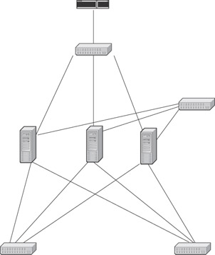
This configuration shows a DMZ server cluster. All systems in the cluster maintain an active connection to other systems in the cluster via the hub. The only system in the cluster that maintains active connections outside the failover information hub is the active DMZ system. When the primary DMZ system fails, it deactivates (or is deactivated) via information over the failover communication network, and the next system in the cluster brings up its network interfaces to perform the job of the primary DMZ server.
We must also consider the need for high availability. In Figure 3.15, we have a configuration that differs slightly from a standard DMZ.

Figure 3.15: DMZ Servers in a Conceptual Highly Available Configuration
Figure 3.15 contains many features similar to those in a typical DMZ. However, what is different is that rather than one DMZ system connected to the external network switch, three DMZs are connected to the external network switch. Additionally, there are several connections from these DMZ systems to the same public and private networks. We also see a connection between the DMZ systems.
The PIX Failover Services
When your DMZ design calls for a highly available firewall solution because downtime due to a problem with the firewall hardware will not be tolerated, consider using the PIX's failover feature. The failover feature allows you to set up a second PIX in Standby mode, and if the primary, or active, PIX should go offline, the secondary PIX will switch to Active mode and take over for the failed PIX. If the optional stateful failover feature is configured, the secondary PIX can maintain operating state for active TCP connections during failover, so users will not lose their sessions as the PIX fails over to its backup unit. In order to enable failover, the primary and secondary PIX firewalls need to be identical in terms of chassis, OS version, and hardware options.
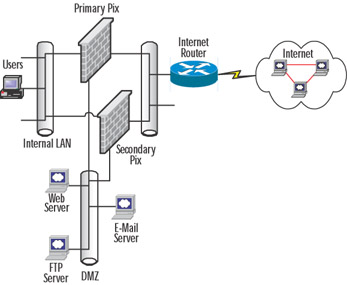
If high availability is required, the DMZ architect can consider adding a second PIX in conjunction with the PIX's failover feature, which allows the secondary PIX firewall to back up the primary PIX in the event of a failure. Figure 3.16 shows how redundancy can be added to the traditional "three-legged'' firewall design. This design is ideal for corporations of all sizes, where the Internet/DMZ infrastructure is essential to the business and therefore they cannot afford downtime and require a resilient, highly available solution. Both the primary and secondary PIX firewalls need to be identical models and have the same interface options. Each PIX will have an interface on the internal, external, and DMZ LANs. When set up as a redundant pair, the PIX has the ability detect problems within the units or on any of the interfaces and automatically failover to the backup unit. The PIX offers the option of stateful failover, which means that any open sessions on the primary will be automatically transferred to the secondary unit without client sessions disconnecting, so the failure is transparent to end users. In order for the PIX to support failover, some additional hardware is required, such as an additional interface to support the optional stateful failover feature, and a Cisco proprietary cable for heartbeats between the primary and secondary units. .

Figure 3.16: Traditional "Three-Legged" Firewall with Redundancy
The PIX offers two options that provide connectivity for the primary and secondary PIX firewalls to exchange heartbeats and configuration information. The first option is a Cisco proprietary high-speed serial cable connected to a special serial failover port on the PIX. The second option is to use one of the PIX LAN interfaces to carry heartbeat and configuration traffic. The advantage of using the Cisco proprietary high-speed serial cable to send heartbeat and configuration traffic is that it will not waste a LAN interface for a rather small amount of traffic. Instead, it uses a serial port specifically designed for failover. The disadvantage is that the high-speed serial cable is rather short (six feet long), and if the PIX firewalls are not physically located close together, you cannot use the cable-based solution because the cable cannot be extended. If you have a situation in which the PIX firewalls are not physically located together, you can consider the second option, a LAN-based failover, which uses interfaces on each PIX to provide dedicated media for heartbeat and configuration traffic. The disadvantage of this option is that an interface on each PIX will be wasted just for heartbeat and configuration traffic. It is important to note that heartbeat and configuration traffic should not be confused with state traffic used for the stateful failover option, which the active PIX uses to send the standby PIX TCP state information. Although you can configure the PIX to carry heartbeat, configuration, and state traffic all on one interface on each PIX using the LAN-based failover option, doing so is not recommended.
When failover occurs, the standby PIX assumes all the IP addresses and MAC addresses on all interfaces of the failed PIX. Because there is no change to the IP address or MAC address information, other devices on the network will not be aware of a failure and that they are now communicating through a different device. Another feature of failover is that when a configuration change is made to the primary, it is automatically copied to the secondary PIX, and when a write memory command to save the configuration to Flash is issued on the primary, it also copies the configuration to the secondary's Flash.
What Causes Failover to Occur
To determine the health status of each PIX, the primary and secondary PIX poll each other. The poll interval is set using the failover poll command; the default is 15 seconds. Polls, also called heartbeats, are sent over all interfaces, including the failover cable. If either PIX misses two consecutive heartbeats, each PIX will go through a series of tests to determine which PIX is in trouble. Each unit goes through four tests to determine its health: a Link Up/Down test, a Network Activity test, an ARP test, and a Broadcast Ping test. Each PIX firewall performs one test at a time. If a unit passes a test and the other unit does not, the PIX that passed will take over. If both PIX units fail, they move on to the next test. At the default poll interval (15 seconds), the PIX units can take up to 45 seconds to run through all the tests and determine if failover should take place.
|
EAN: 2147483647
Pages: 240