ISDN Planes: ISDN Layer Architecture
| As with every technology, the ISDN architecture creates a framework for more informed decision making, including appropriate investments in network technologies, products, and services. The CCITT defines the ISDN architecture to consist of four planes:
The C-plane primarily deals with UNIs and establishing and tearing down the calls, and, the U-plane deals with User-Network data carried by the B channel. When troubleshooting ISDN, it is important to remember how the ISDN protocol architecture relates to the OSI reference model. Unlike other technologies, ISDN covers the physical, data link, and network layers, which match the first three layers of the OSI model. The three protocol layers for the B and D channel are defined in the following list and in Table 9-1:
Table 9-1. OSI and ISDN Layers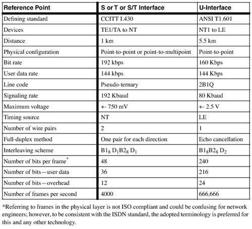 [View Full Width] In the point-to-point physical connections, the NT (NT1 or NT2) and the TE (TE1 or TA) can be 1 km (3300 ft) apart. The passive bus (no repeaters or any active devices) point-to-multipoint design allows up to eight devices to be connected to a single NT on a bus length that can be up to 200 m (667 ft). The extended bus supports up to eight devices clustered together at the end of the passive bus and can be up to 1 km (3300 ft) apart from the NT. The sections that follow discuss all three ISDN layers in greater detail. Layer 1: BRIISDN standards require the availability of three types of services for end-to-end connections by the local exchange carrier (LEC):
To use them, the ITU-T defined BRI and PRI access interfaces, and the operation speed and the number and type of channels. The BRI is also referred to as 2B+D, and typically operates over two 64-kbps B channels and one 16-kbps D channel. It can also be provisioned as 1B+D, and even 0B+D for low speed (9.6 kbps) data. As you can see, the D channel in BRI operates at 16 K, but in its S/T implementation, the speed is 192 Kbps. It looks like we are losing 48 Kbps. We're actually not. The remaining 48 Kbps can be used for out-of- band forward error correction (OOB FEC). The following sections cover the elements of a typical ISDN BRI architecture:
ISDN DevicesThe hardware that is part of an ISDN service includes the following:
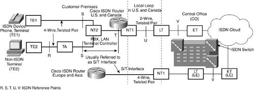
In the CPE site, the local loop is terminated by using an NT1, which is responsible for performance monitoring, timing, physical signaling, protocol conversion, power transfer, and multiplexing of the D and B channels, as shown in Figure 9-2. Figure 9-2. ISDN Devices and Access Points The NT1 devices in Europe and Asia belong to the LEC. It is an external device for the router. ISDN Local Loop Reference Points: ISDN InterfacesISDN service providers (those providing the last mile or the local loop of the ISDN connection) refer to reference points when troubleshooting parts of the local loop. To connect devices that perform specific functions, the devices need to support specific interfaces, which can vary from CPE to CPE. As a result, the ISDN standards do not define interfaces in terms of hardware, but refer to them as reference points. However, for troubleshooting purposes, it is more reasonable to refer to interfaces. Every ISDN compatible router provides information about the type of connection or interface; and Cisco 77x, 80x, 25xx, and 40xx series routers are examples. These interfaces are as follows :
The real structure of every ISDN design includes numerous implementations. For troubleshooting purposes, it is preferable to simplify the diagram of reference points and interfaces to the illustration (refer to Figure 9-2). In most common cases, consider the simpler structure. For residential and Centrex applications, the NT2 is absent. NOTE The book Analyzing Broadband Networks , now in its third edition, provides some excellent examples of ISDN architecture and design. Both the S/T and U-interfaces achieve full-duplex connections. The current wiring rules follow the ISO 8877 standard. RJ-45 is an 8-pin connector. Table 9-2 shows the wiring rules for the S/T interface and Table 9-3 shows the U-interface wiring rules. The polarity is important only for the S/T interface. Table 9-2. ISDN RJ-45 Pins for the S/T Interface
Table 9-3. ISDN RJ-45 Pins for the U-Interface
Chapter 3 covers the S/T interface and U-interface line codes and frame formats in greater detail. Table 9-4 describes the physical characteristics of both interfaces and their differences. Table 9-4. Standards Defining the Physical Characteristics of the S/T and U-Interfaces
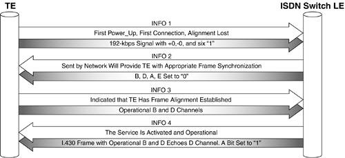
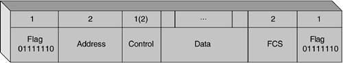
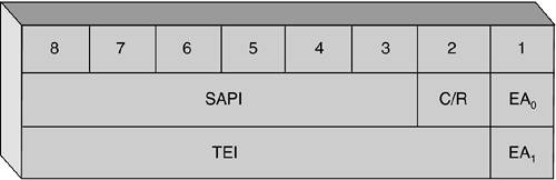
For more information, see ISDN Concepts, Facilities, and Services , Third Edition (McGraw-Hill, 1996). Initializing BRIActivation of the BRI is based on the exchange of INFO messages and on the performance of a straightforward handshake mechanism. I.430 defines 5 INFO (0-4) messages that perform different roles in the activation process. As Figure 9-3 shows, the process starts with the TE sending INFO1 to the LE. The A bit that's set to 1 indicates that the line is activated. The INFO0, which is not shown in this figure, indicates "no signal." Figure 9-3. Initializing the Physical Link The Layer 2 D Channel: LAPDAs discussed previously, on the second layer of the layered model, ISDN uses a protocol called LAPD. The protocol's general principles are defined in the Q.920 (I.440) and the Q.921 (I.441) standards. The following is a discussion of Layer 2 frame formats, logical link establishment, and logical link parameter negotiation, which are related to Layer 2 troubleshooting later in this part. LAPD Frame Formats (A and B)Two formats, A and B, are defined in LAPD. Format A differs from B, and it is used where the information field is not necessary. Because Format A is a subset of Format B (Format B is identical to Format A with the addition of an Information field), the following explanation will apply to both. Figure 9-4 shows the format of every transmission unit (frame). Figure 9-4. LAPD Format B Frame The first row represents the number of octets, and the second row the actual fields. Unlike other frame types, the low-order bit of each octet is transmitted first. In this case, it is the last bit (0) in the Flag field, the last bit of the first octet of the Address field, and so forth. Flag FieldThe Flag field has a standard value of 0x7E(01111110) and indicates the beginning and the end of the frame. The combination 0x7F(01111111) represents the abort signal, and the combination 0xFF (11111111) represents an idle channel. The Flag begins and ends the frame. Address FieldThe Address field identifies the user device and protocol, and it plays a significant role in the troubleshooting process. It is always two octets. The structure is shown in Figure 9-5. Note that the remaining 13 bits represent the data-link connection identifier (DLCI)a combination of the TEI and service access point identifier (SAPI) fields. The terminal endpoint identifier (TEI) is designed to maintain a separate logical link over the D channel with the peer process in the LE. Figure 9-5. The Structure of the Address Field. The TEI and SAPI Fields Represent a 13-Bit DLCI The Address field has the following subfields:
Control FieldThe Control field of LAPD is used for frame identification. The field can be one or two octets, and provides messages that perform some of the typical functions for the Transmission Control Protocol (TCP), such as ACK and SEQ#. The Control field uses three frame formats, which are indicated by the first two bits of the field: Information, Supervisory and Unnumbered. Information (I) is a two-octet frame field that carries signaling or user data information from higher ISDN layers. Supervisory (S) is also a two-octet field format that controls the exchange of the I-frames. When troubleshooting, it is not easy to recognize the message types. The following descriptions help with the identification. NOTE Every message is either a command or a response (R), based on its purpose. P/F is a poll/final bit, S is S-frame type, and M is U-frame type. Based on the content of messages in the Control field of LAPD, three categories of messages exist:
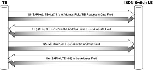
Data FieldThe Data field contains Q.931 messages, user data, or LAPD management information. The Data field has a variable, octet-aligned length, and it might not exist in all frames. FCS FieldThe frame check sequence (FCS) field is two bytes and it is used for bit error detection. Logical Link EstablishmentThe next step of achieving full functionality of ISDN service, immediately after the activation of the physical link, is the logical link establishment. Here, LAPD ensures the TEI and SAPI assignments, which are the core of the logical link establishment, as shown in Figure 9-6. The figure represents another handshake link procedure. Figure 9-6. Logical Link Establishment Sequence You can distinguish two main phases in the process:
In the most common 2B+D design of a BRI, this procedure executes twice, once for each B channel. Therefore, by the end of the exchange, every B channel has an assigned TEI = xx and SAPI = 0. Logical Link Parameter NegotiationThe logical link establishment is more complicated than a physical connectivity establishment. One of the reasons is that the router and the ISDN switch need to negotiate some parameters. There is a mechanism to negotiate some timers values and counters values to adjust the service to the line parameters. In LAPD, the parameters' negotiation function is accomplished through a system of timers and parameters that are exchanged between parties with a U-type XID frame. One device sends the XID frame with its parameters, and if the other device does not respond with another XID, the first one considers the negotiation complete by using the default parameters. Some of the system parameters and their default values are listed here:
Some of the system timers and their parameters are as follows:
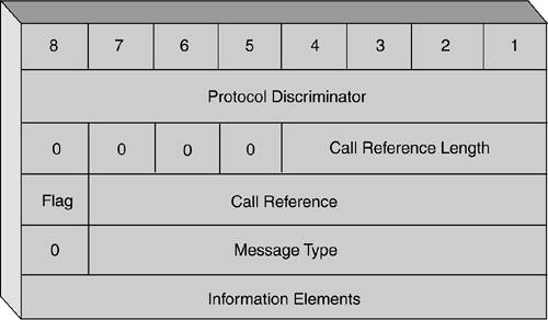
In addition to the perfect scheduling mechanism for the LAPD layer mentioned earlier, another mechanism makes sure that no TE has full control over the D channel. This technique is based on analyzing the SAPI content and creating a priority mechanism based on classes. In this case, the signaling SAPI = 0 messages are class 0, and non-zero SAPIs are class 2. Both normal and low priority classes exist, which are based on the number of consecutive 1s in the frame. Using ISDN in an IP environment is usually related to the PPP and to one of the phases of the PPP protocol, called the Link Control Protocol (LCP), which are discussed in detail in Chapter 5, "Dial Technology Background," and Chapter 13, "Troubleshooting Scenarios for ISDN BRI." It is important to know that LCP does not replace, but works together, with parameter negotiation mechanisms of ISDN. RFC 1618 was created to ensure this feature. Layer 3 in the D Channel: Q.931 and Message FormatThe term Layer 3 protocols comes from the network layer in OSI, and the Q.931 recommendations provide call routing and congestion control for calls between a user's TE and the network (between the terminal endpoint and the local ISDN switch). However, this protocol does not impose an end-to-end recommendation, and various ISDN providers and switch types use various implementations of Q.931. Also, some switch types were developed before the standards groups finalized this standard. For these reasons, the proper specification of the switch in Cisco routers is important. The recommended Q.931 message formats represent data blocks, called information elements. SS7 provides telephone switches with the out-of-band signaling capabilities for telephone trunks (switch-to-switch 64-kbps connections). Unlike old in-band signaling standards, out-of-band Signaling System 7 (SS7) provides reduced call setup time, 64-kbps data, caller ID, dialed number information (DNIS), bearer capability, and other progress indicators. The Q.931 protocol typically provides the information shown in Figure 9-7. ISDN Layer 3 messages are carried in the Information field of LAPD I-frames. Q.931 messages are used in the debugging process with Cisco routers and deserve detailed attention. Figure 9-7. Message Format of the Q.931 Protocol Protocol Discriminator FieldThe first field of the Q.931 message format depicted in Figure 9-7 is the Protocol Discriminator field. It identifies the protocol type such as Q.931, X.25, and others. The protocol discriminator has a few values that are used by ISDN:
Call Reference FieldThe second field is the Call Reference (CR). It identifies the relationship between the call and the message, where the number identifies the active calls. CR or the Call Reference Value (CRV) is a per-session /per-connection value that is assigned at the beginning of the call, and remains the same until the call is completed. Often the only indicator of whether or not the call goes through is tracing the call and testing with the LEC. Typically, a BRI uses one octet CR length, and a PRI uses two. The high-end bit of the second octet is called a Flag. To prevent the assignment of one CR to two different calls, the Flag is set as follows:
A special CR is defined with 0 value to indicate a broadcast, which is assigned to all active calls in the user-network interface. Message Type FieldThe Message Type value indicates the type of Layer 3 message that the transmission represents. Call establishment message types in Q.931 are as follows:
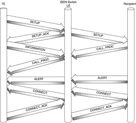
Figure 9-8 shows the process of connecting a call. Figure 9-8. The Call Setup Procedure: The Switch Handles Both Directions The initiator of the call (the router) sends a SETUP message, and usually provides the bearer capability, the calling party number, and the number of the B channel that is starting the call. The bearer capability defines the type of service requested , such as 64-kbps data, 56-kbps data, or 56-kbps voice. The SETUP message also contains the channel identification element, which is designed to be negotiated with the switch, depending on where the call hits the network. After this is completed, both parties know each other's per-session numbers . After receiving the SETUP message and checking for correctness, the LE usually requests any missing information with the SETUP_ACK. Then, the router provides this information (see the arrow "INFORMATION" in the figure). If the information is correct and sufficient, the LE responds with CALL_PROC (call proceeding). So according to Figure 9-8, it should be read as either of the following:
The LE generates a different SETUP message and sends it to the Recipient, which can be thought of as a PRI connecting to the core router. If the Recipient cannot accept the call, it sends an ALERT to the LE, which in turn generates another ALERT message from the LE to the CPE. When the Recipient accepts the call, it sends a CONNECT to the LE and the LE responds with a CONNECT_ACK. In turn , the LE generates a CONNECT message, which informs the router that the call is accepted and the router responds with a CONNECT_ACK. The call clearing messages are as follows:
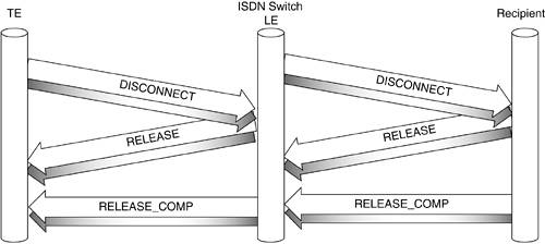
The call clearing can be started by any party by sending a DISCONNECT message. Figure 9-9 shows the call clearing procedure, where the DISCONNECT is initiated by the router. After the router sends the DISCONNECT, it disconnects itself from the B channel. The LE returns a RELEASE and in turn, sends a DISCONNECT message to the Recipient. While the Initiator completes the process by sending RELEASE_COMP, the LE releases the B channel. On the other side, after the LE and the Recipient exchange RELEASE and RELEASE_COMP messages, the facility is released for new calls. Figure 9-9. The Call Clearing (Tear Down) Process Information Elements FieldAs previously mentioned, the data is carried in the Information Elements (IE), which are the Q.931 parameters. Unlike other protocols, Q.931 does not define a fixed length for this field that reflects the actual length of the field. Different content and different length works with different LECs. For this reason, this field might contain a length indicator, defined as Type 1 and Type 2 IE. The Type 1 IE defines a 3-bit identifier and 4 bits for the content of IE, and Type 2 contains a 7-bit IE identifier. The most common IEs are listed here and more are described in Q.922:
Layer 3 SummaryThe Layer 3 procedures are designed to provide the full functionality of handling the calls, including establishing, connects and disconnects, releasing the facilities for the next calls, and so forth. As discussed earlier, all these functions are performed between two or more parties, but the main role always belongs to the ISDN switch, which naturally leads to the topic of the next section. |
EAN: 2147483647
Pages: 235