Advanced Frame Relay Configurations
| The represented configuration solutions in the following sections are usually referred to as advanced Frame Relay configurations. They include the following:
Configuring IP Unnumbered Frame RelayOne of the IP preservation schemes that is only applicable for point-to-point configurations is to use an unnumbered IP address. In Example 16-4, you can see that for the core router configuration the physical interface is configured with no ip address and the IP addresses are assigned to the subinterfaces. These IPs are all obtained from the Loopback0 interface. Given the number of configured subinterfaces, you can see how this approach maximizes the use of available IP address space. The same logic applies to the remote user's router configuration in Example 16-7, where the subinterfaces obtain IPs from the Ethernet0 interface and, thus, the overall solution doubles the number of spared IPs. Frame SwitchingWhen discussing Frame Relay technology options in Chapter 14, Frame switching and a set of protocols were introduced (refer to Figure 14-2 and Figure 14-3). Typically, a router is configured as data communications equipment (DCE) if it is connecting directly to another router. It can also be configured as DCE when connected to a 90i D4 channel unit, which in turn is connected to a telephone company (telco) channel bank. A variety of configuration solutions exist for frame switching, including the following:
The full range of configuration examples are beyond the scope of this section, but here are some guidelines about the first and second configuration examples. The first switch configuration requires three configuration commands. They are frame-relay switching, frame-relay intf-type dce, and frame-relay route. Consequently, the configuration of frame switching (configuring the Cisco router as a DCE device) includes three steps:
Assume that the top router in Figure 16-2 performs DCE functions for all four of the spoke routers. The DCE configuration rules are as follows:
NOTE In Cisco IOS Software release 12.1(2)T and later, the frame-relay route command is replaced with the connect command. This command is defined in global configuration mode, and the format is as follows: 7206-frame(config)#connect connection-name interface dlci interface dlci The second configuration allows two or more Cisco routers that are configured as DCE to use NNI signaling between them, and to provide DTE to DTE switching. Assume that Figure 16-2 has not one, but two top routers. You need to perform a two-step configuration:
In case you want to simulate the future architecture before implementing the new configuration, you might consider using the Adtran simulator as a Frame Relay switch. This device allows you to simulate a telco channel bank and offers a convenient web-based tool for mapping DTEs. Adtran's ATLAS 890 and the 800PLUS/810PLUS with Frame Relay Software installed enable LAN-to-LAN interconnections by using an integral IP router with support for Frame Relay or PPP traffic (www.adtran.com/all/Public/framemacro?section=products.clec). Frame Relay and ISDN Backup ConfigurationEnterprises that require a wide-area network (WAN) service for long periods of the workday normally choose Frame Relay as a primary link. To prevent situations where this link is a single point of failure, and to meet the availability and redundancy requirements of the design, the ISDN is often used as a backup technology. In the remote access enterprise environment, remote users don't usually warrant a backup. It is up to the enterprise to determine if the additional cost of an ISDN backup is worth the added redundancy. Usually, ISDN backup for Frame Relay is deployed in field sales offices. The following section provides configuration guidelines for the common ISDN backup, ISDN backup with dialer profiles, and ISDN backup that is based on HSRP. Other solutions, such as dialer watch as an alternate backup method, won't be discussed in this section, but can be seen in Chapter 6 and are applicable in Frame Relay. Common ISDN Backup Configuration for Frame RelayThe backup ISDN interface can be defined in both point-to-multipoint and point-to-point interfaces. Depending on the strategy, ISDN BRI0 can back up both the physical and per-DLCI interface. In the physical interface backup scenario, losing the PVC does not trigger the backup mechanism because it only works when there is a complete loss of connectivity (i.e., when both the interface and line protocol are down). Most probably, this is the reason that this method is called physical interface backup. In the per-DLCI scenario, the main interface can stay up, but if the subinterface goes down, the ISDN BRI0 comes up. The physical interface backup (if configured) takes precedence over any other backup configuration. The per-DLCI configuration is the recommended one for practical use. Assume that you need to back up the DLCI 200 (point-to-point interface) that is included in Figure 16-2, and the top router has an ISDN BRI0 interface. The configuration command sequence must include the commands in Example 16-8. Example 16-8. ISDN Per-DLCI Backup Configuration7206-frame#configure terminal 7206-frame(config)# interface Serial4/2:0.200 7206-frame(config-if)# frame-relay interface-dlci 200 7206-frame(config-if)# backup interface BRI0 7206-frame(config-if)# backup delay 5 10 The last command represents the IOS interface configuration command backup delay enable-delay disable-delay. This command specifies enable delay, which is the number of seconds to wait after the primary link has failed before the backup line is brought up; and disable-delay, which is the number of seconds to wait after the primary link is available before the backup line is torn down. In this example, enable-delay is five seconds and disable-delay is ten seconds. Cisco recommends two rules of thumb in this situation:
NOTE Load-based backup, based on load-threshold calculations, is not available in Frame Relay and is applicable only for ISDN. (See Chapter 11, "Cisco ISDN Configuration Solutions.") Frame Relay Backup with ISDN Dialer ProfilesThis solution is based on creating dialer profiles on both the hub and spoke sides. Assume that you have a configuration with one hub and four spoke routers, as shown in Figure 16-2. If all the spoke routers have ISDN backup links available, they can be configured as shown in Example 16-9. As soon as Serial1.201 goes down, the backup ISDN interface comes up according to the configuration settings. Here, the backup delay settings are five seconds for enable-delay and ten seconds for disable-delay parameters (see the line backup delay 5 10). Example 16-9. Fragment of the Spoke Router Configuration with Per-DLCI Backup Configured Under the Interface Serial1.201 <output omitted> ! interface Serial1.201 point-to-point ip unnumbered Ethernet0 bandwidth 128 frame-relay interface-dlci 201 backup delay 5 10 backup interface BRI0 ! <output omitted> Now assume that the core router has one backup Basic Rate Interface (BRI) (BRI0) and you want to configure the dialer profiles for this router. This configuration has two major steps. The first step is to configure four dialers (D1-D4) to guarantee one BRI channel per spoke router. This step was discussed in Chapter 11. The second step is to assign BRI interfaces to every pool. Again, refer to Chapter 11 for configurations of dialer pools. The difference here is that to guarantee one BRI channel per every spoke router, you have to restrict the number of channels by using the commands in Example 16-10 under the BRI0 interface. Example 16-10. Dialer Pool Member Configuration for the Core Routerdialer pool-member 1 max-link 1 dialer pool-member 2 max-link 1 dialer pool-member 3 max-link 1 dialer pool-member 4 max-link 1 If the probability of failure is high, it is better to use a PRI, instead of a group of BRIs, and apply the same configuration rules. In this case, you can consider using multilink ppp. Troubleshooting the solution should follow the methodology described in Chapter 17, "Frame Relay Troubleshooting," and Chapter 12. It is not recommended to use the shutdown command on the serial interface to test this solution. Instead, you can emulate a real serial line problem by pulling the cable out from the serial line. EIGRP- and HSRP-Based SolutionsA more sophisticated backup mechanism is available in Cisco IOS using the EIGRP routing protocol and a combination of floating and static routing. Both one- and two-router based configurations are available. For a full description of the solutions, see the Cisco Press book Advanced IP Network Design (CCIE Professional Development) by Alvaro Retana, Don Slice, and Russ White. An important element of the configuration is to prevent an IP route-cache on the ISDN configuration because the router sends traffic over this interface even after the primary connection is restored. A weakness of this solution is that the configuration still relies on the status of the physical connectivity. It is well known that even when the physical layer is up, this does not necessarily mean that IP connectivity is up. In other words, losing IP connectivity might not trigger the backup mechanism. Another interesting solution is related to HSRP and its functionality. HSRP allows routers to share a virtual IP address between them with only one active HSRP router accepting (and forwarding) traffic destined to that virtual IP. In the latest IOS releases, HSRP provides monitoring and prioritizing capabilities, which result in proper fail-over for devices when a redundant serial link failure occurs on a router. The solution is based on the IOS track and preempt commands that identify the primary router as a higher priority over the backup one. As soon as the primary link fails (interface Serial3/0:0), the standby 1 track Serial3/0:0 command reduces the value of priority, so the backup router now has a higher priority value and becomes the primary router. More about this topic can be found at www.cisco.com/warp/public/619/6.html. Frame Relay and BridgingWhen using Frame Relay bridging, there must be a full mesh of Frame Relay virtual circuits between the bridges of a remote bridge group. If the Frame Relay network is not a full mesh, the bridge network must be divided into multiple remote bridge groups. Because LMI transforms the Frame Relay to a LAN-like architecture, this bridging model is identical to the model for remote bridging as described in IEEE P802.1g, which supports the concept of virtual ports. The Frame Relay virtual circuits that interconnect the bridges of a remote bridge group can be combined or used individually to form one or more virtual bridge ports. This solution provides flexibility to treat the Frame Relay interface as either a single virtual bridge port with all virtual circuits in a group, or as a collection of bridge ports (individual or grouped virtual circuits). The simplest bridge configuration for a Frame Relay network is the LAN view, where all virtual circuits are combined into a single virtual port. Frames, such as Bridge Protocol Data Units (BPDUs), which are broadcast on a LAN, must be flooded to each virtual circuit (or multicast, if configured on the Frame Relay network). Flooding is performed by sending the packet to each relevant DLCI that is associated with the Frame Relay interface. Obviously, this approach is typical for point-to-multipoint configurations. A second Frame Relay bridging approach for point-to-point configurations treats each Frame Relay virtual circuit as a separate bridge port. Flooding and forwarding packets are significantly less complicated by using the point-to-point approach because each bridge port has only one destination. There is no need to perform artificial flooding or to associate DLCIs with destination Media Access Control (MAC) addresses. In Example 16-11, a simple bridge configuration (fragment) is provided. The defined subnet of the spoke router is /29 (the subnet mask is 255.255.255.248), and it is a subnet of the core router. Therefore, from the available six addresses for the spoke router, the first address (in this case, 54.161.107.161) is the default route. The spoke is bridging, but the core is routing the packets. Example 16-11. Cisco 1602 Router, Configured as a Bridge 1602-frame#show running-config <output omitted> ! bridge irb ! interface Ethernet0 no ip address no cdp enable bridge-group 1 hold-queue 32 in ! interface Serial1 no ip address encapsulation frame-relay no ip mroute-cache no fair-queue service-module t1 timeslots 1-2 frame-relay lmi-type ansi ! interface Serial1.201 point-to-point ip unnumbered BVI1 bandwidth 128 frame-relay interface-dlci 201 bridge-group 1 ! interface BVI1 ip address 54.161.107.162 255.255.255.248 ip nat outside ! ! ip nat inside source list 1 interface BVI1 overload The first important line in this configuration is the command bridge irb. It enables the Integrated Routing and Bridging (IRB) feature. This feature allows a given protocol to be routed between routed interfaces and bridge-groups or between bridge-groups within a single router. Specifically, local or unroutable traffic is bridged among the bridged interfaces in the same bridge-group, and routable traffic is routed to other routed interfaces or bridge-groups. So again, why use IRB? Here are some reasons:
The second important part of this configuration is the Bridge Group Virtual Interface (BVI). The concept of BVI was created to enable these interfaces to exchange packets for a given protocol. The BVI is a virtual interface within the router that acts just like a normal routed interface. It does not support bridging but represents the corresponding bridge-group within the router. This virtual interface allows routing between a bridge-group and a routed interface. Because bridging is in the data link layer and routing is in the network layer, they have different protocol configuration models. With IP, for example, bridge-group interfaces belong to the same network and have a collective IP network address, and each routed interface represents a distinct network and has its own IP network address. The interface number of the BVI (#1 in Example 16-11) is the number of the bridge group that this virtual interface represents. The number is the link between this BVI and the bridge group. When you configure the BVI and enable routing on it, packets that come in on a routed interface are destined for a host on a segment that is in a bridge group that goes through the following processes:
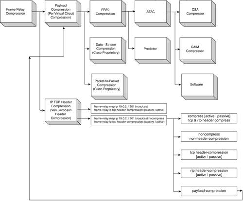
Similarly, packets that come in on a bridged interface but that are destined for a host on a routed network first go to the BVI. The BVI then forwards them to the routing engine before sending them out the routed interface. Interfaces Ethernet 0 and Serial1.201 are members of bridge group 1, as defined by the virtual bridge interface (BVI1). As soon as the BVI1 has an IP address assigned to it, Serial1.201 obtains an IP address. Then the router bridges the frames from E0 to BVI1, and vice versa. Network Address Translation (NAT) is also an important part of the configuration, but it was already discussed in this book and does not require any further attention. NOTE To check if the bridge is working, add and remove an IP routing statement, such as 1602-frame(config)#ip route 0.0.0.0 0.0.0.0 BVI1 The routing statement should not affect the ability of the router to pass traffic. Frame Relay CompressionCisco internetworking devices use the STAC (LZS) and Predictor data compression algorithms. STAC (LZS) is based on the Lempel-Ziv compression algorithm. Cisco IOS Software uses an optimized version of LZS that provides good compression ratios but requires many CPU cycles. LZS searches the input data stream for redundant strings and replaces them with what is called a token. This token is shorter than the original data string. LZS creates dictionaries. This dictionary is built and begins replacing the redundant strings that are found in the new data streams. The Predictor compression algorithm tries to predict the next sequence of characters in the data stream by using an index to look up a sequence in the compression dictionary. It then examines the next sequence in the data stream to see if it matches. If it does match, that sequence replaces the looked-up sequence in the dictionary. If not, the algorithm locates the next character sequence in the index and the process begins again. The Predictor data compression algorithm was optimized by Cisco engineers. When compared with LZS, it makes more efficient use of CPU cycles but requires more memory. The compression alternatives within Frame Relay include two main groups: per-interface compression (also called link compression) and per-virtual circuit compression (also called payload compression). The available Cisco compression solutions for Frame Relay are shown in Figure 16-3. Figure 16-3. Cisco Frame Relay Compression Solutions
Depending on which part of the packet you want to compress, several available options exist: header compression (TCP and RTP header compression); payload compression (FRF.9, stacker, predictor; and Microsoft Point to Point Compression [MPPC]). MPPC is based on RFC 2118 and is a per-Point-to-Point Protocol (PPP) connection compression algorithm. NOTE Shut down the interface or subinterface prior to adding or changing compression techniques. Although not required, shutting down the interface ensures that it is reset for the new data structures. Van Jacobson Header CompressionCisco IOS header compression uses the Van Jacobson Algorithm as defined in RFC 1144. Cisco's header compression product supports X.25, Frame Relay, and dial-on-demand WAN link protocols. Because of the processing overhead, header compression is generally used at 64 kbps. For example, a 50 percent throughput improvement can be achieved with telnet, rlogin, and X Windows traffic on a 64-kbps leased line for TCP/IP, which conforms to RFC 1144. Example 16-12 shows an interface configured for TCP/IP header compression and an IP map that inherits the compression characteristics. The Frame Relay IP map is not explicitly configured for header compression. Example 16-12. The Interface Serial1 and IP MAP with Inherited TCP/IP Header Compression 1602-frame#show running-config <output omitted> interface Serial1 no ip address encapsulation frame-relay no ip mroute-cache no fair-queue service-module t1 timeslots 1-2 frame-relay lmi-type ansi frame-relay map ip 10.0.2.1 201 broadcast frame-relay ip tcp header-compression passive <output omitted> NOTE The frame-relay ip tcp header-compression [passive | active] command has two options. The passive option indicates that the TCP header compression is active only for the destinations that are sending compressed headers. The active option requires the other side to be configured for the same type of compression. If you type 1602-frame#show frame-relay map, you see a line that looks similar to the following: <output omitted> dlci 201 (0xC9,0x3090), static, broadcast, CISCO TCP/IP Header Compression (inherited), passive (inherited) <output omitted> This shows that the IP map has inherited passive TCP/IP header compression. This example also applies to dynamic mappings achieved with the use of InARP on point-to-point subinterfaces, where no Frame Relay maps are explicitly configured. Another configuration option is to override the compression set on the interfaces, as shown in Example 16-13. Example 16-13. Compression, Configured for Interface Serial1 Using an IP Map to Override TCP/IP Header Compression 1602-frame#show running-config <output omitted> interface Serial1 no ip address encapsulation frame-relay no ip mroute-cache no fair-queue service-module t1 timeslots 1-2 frame-relay lmi-type ansi frame-relay map ip 10.0.2.1 201 broadcast nocompress frame-relay ip tcp header-compression passive <output omitted> NOTE If the interface is configured with IETF encapsulation, it cannot be configured for header compression and map compression must be configured. The interface configured for TCP/IP header compression cannot support priority or custom queuing. Use the show frame-relay map command to display the resulting compression and encapsulation characteristics: 1602-frame#show frame-relay map <output omitted> dlci 201 (0xC9,0x3090), static, broadcast, CISCO <output omitted> Because IP map did not inherit the TCP header compression, the keyword inherited is not reported in the output. Per-Virtual Circuit Compression (Payload Compression)The Frame Relay Forum (FRF) Technical Committee approved an implementation agreement for data compression over Frame Relay called FRF.9. This agreement specifies a standard for compression to ensure multivendor interoperabilitysee Frame Relay Standards in Chapter 14. FRF.9 is a per-virtual circuit compression mechanism for both switched virtual circuits (SVCs) and permanent virtual circuits (PVCs), which is negotiated at the time that the DLCI is started. Cisco currently supports FRF.9 mode 1 and is evaluating mode 2, which allows more flexibility for parameter negotiation. Payload compression has several options. From the core side of the router, the available options are shown in Example 16-14. Example 16-14. Configuration Interface Serial4/2:0.200 for FRF.9 Payload Compression on the Core Router 7206-frame#show running-config <output omitted> ! interface Serial4/2:0.200 point-to-point description 1602-frame: 10.0.2.1/29 bandwidth 128 ip unnumbered Loopback2 no ip route-cache frame-relay class class-128-new frame-relay interface-dlci 200 IETF frame-relay payload-compression FRF9 stac csa 2 ! <output omitted> In Example 16-14, subinterface Serial4/2:0.200 uses payload FRF.9 stacker compression, as performed on the compression service adaptor (CSA) hardware module 2(compression service module 2). The syntax of the command is as follows: frame-relay payload-compression encapsulation-option stac compressor-option The values for encapsulation-option include the following:
FRF.9 stacker compression can be performed by a Cisco Advanced Integration Module (CAIM), a CSA, or by the main processor: frame-relay payload-compression FRF9 stac compressor-option The word stac stands for stacker (LZS) compression. The values for compressor-option include the following:
NOTE In the core router, as soon as you use payload compression, switch off the fancy switching. The only available option is to use process switching. From the spoke perspective, a couple of configuration options are available, as shown in Example 16-15. For 1600 router series, there is no hardware compression module available. Example 16-15. Software Compression Configuration of a 1600 Router 1602-frame#show running-config <output omitted> ! interface Serial1.200 point-to-point bandwidth 128 ip unnumbered Ethernet0 no ip mroute-cache frame-relay interface-dlci 200 IETF frame-relay payload-compression FRF9 stac software <output omitted> In the output in Example 16-15, you can use either the stacker software compression or the Cisco proprietary packet-to-packet compression. Both options are always available. For the Cisco 2600 series and 3660 series routers, the CAIM is available. For more details about hardware compression modules, see www.cisco.com. Frame Relay and IP Multicast ConfigurationTo provide basic multicasting over ISDN and Frame Relay for a remote access environment, you must perform some basic tasks:
In a Frame Relay environment, the following steps provide basic multicast for users. On the spoke router, the lines in Example 16-16 must be configured. Example 16-16. Basic Configuration Steps for IP Multicast on the Spoke Router1602-frame#configure terminal 1602-frame(config)# ip multicast-routing 1602-frame(config)# ip pim accept-rp auto-rp 1602-frame(config)# interface Serial1.201 1602-frame(config-subif)# ip pim sparse-dense-mode 1602-frame(config-subif)#exit 1602-frame(config)# interface Ethernet 0 1602-frame(config-subif)# ip pim sparse-dense-mode 1602-frame(config-subif)# ^Z 1602-frame# copy running-config startup-config In general, PIM protocol (protocol 103) can be configured for two different modes, which are referred to as dense mode (DM) and sparse mode (SM). PIM DM uses a process of reverse path flooding that is similar to the Distance Vector Multicast Routing Protocol (DVMRP). Unlike DVMRP, it does not require a particular unicast protocol to determine which interface leads back to the source of a data stream. However, it uses whatever unicast protocol is being used in the network. PIM SM defines a rendezvous point (RP), which serves as a registration point to facilitate the proper routing of packets. When a sender wants to send data, the next/first hop sends data to the RP. When a receiver wants to receive data, the last hop router registers with the RP. A data stream flows from the sender to the RP, then to the receiver. Afterwards, routers in the path optimize the path automatically to remove any unnecessary hops, including the RP. The configuration on the hub side router is even simpler because usually the objective is to configure one more user for IP multicast. If this is the case, ip multicast-routing and ip pim accept-rp auto-rp already exist in the configuration, as in Example 16-16. Also, at least one of the Ethernet or FastEthernet interfaces is configured with the ip pim sparse-dense-mode command. The only interface that needs to be configured now is the serial subinterface. If the core router requires an entire new configuration for IP multicast, follow the guidelines in Example 16-17. Remember that only the interfaces configured for multicast can participate in the multicast shared tree. Example 16-17. Sample IP Multicast Configuration of the Core Router7206-frame(config)# ip multicast-routing 7206-frame(config)# ip pim accept-rp auto-rp 7206-frame(config)# interface Serial4/2:0.200 7206-frame(config-subif)# ip pim sparse-dense-mode 7206-frame(config-subif)#exit 7206-frame(config)# interface FastEthernet 0 7206-frame(config-subif)# ip pim sparse-dense-mode 7206-frame(config-subif)# ^Z 7206-frame# copy running-config startup-config In both configurations (Example 16-16 and Example 16-17), ip multicast-routing is configured in the global configuration mode. This step is mandatory because Cisco routers don't forward broadcast or multicast traffic by default. The next line allows PIM to accept the auto-rp. In general, two options can map RP:
The next important part is ip pim sparse-dense-mode, which defines a dual mode configuration. This mode of Cisco IOS is in fact an interface configuration that allows both DM and SM groups to flow across that interface. It is normally only applied when Auto-RP sends RP information. The configuration in Example 16-17 can include either DM or SM. If you need to choose, Cisco recommends PIM SM, rather than DM. For Frame Relay, remember that 56 kbps is not the best service for multicast. Even 128 kbps with compression can affect the end user's router performance significantly, and if the wrong configuration settings are used, it can shut the service down completely. Frame Relay and Traffic ShapingTraffic shaping enables the router to control the output rate and react to the congestion notification mechanisms according to the traffic shaping settings. In Cisco routers, traffic shaping uses a rate control mechanism called a token bucket filter. The token controls the following expression:
Traffic above the maximum speed is buffered in a traffic shaping queue, which is equal to the size of weighted fair queuing (WFQ). The token bucket filter does not filter traffic. Rather, it controls the rate at which traffic is sent on the outbound interface. The parameters defined in traffic shaping are as follows (see Chapter 14 for more information):
Bc, Be, Tc, and CIR are defined per DLCI. Consequently, the token bucket filter controls the rate per DLCI. The access rate is valid per User-Network Interface (UNI). For Bc, Be, and CIR, incoming and outgoing values can be configured. If the connection is symmetrical, the values in both directions are the same. For PVCs, parameters such as incoming and outgoing Bc, Be, and CIR are defined at the time of provisioning. NOTE Peak equals the DLCI's maximum speed and represents the bandwidth for that particular DLCI:
If the Tc is one second:
Generic Traffic ShapingThe generic traffic shaping feature is a media and encapsulation-independent traffic shaping tool. It helps reduce the flow of outbound traffic when there is congestion within the cloud, on the link, or at the receiving endpoint router. You can set it on interfaces or subinterfaces within a router. See Example 16-18 for the following configuration steps. First, you need to enable traffic shaping in the main interface (interface Serial4/2:0) with the following command: frame-relay traffic-shaping Then, under the subinterface, you configure the traffic-shape rate. This command configures traffic shaping for outbound traffic on an interface. The full syntax of this command is as follows: traffic-shape rate bit-rate [burst-size [excess-burst-size]] [group access-list] Finally, if the configuration solution requires you to throttle backward explicit congestion notifications (BECNs) on a Frame Relay interface, the following command is required in the interface configuration mode: traffic-shape adaptive [bit-rate] Example 16-18 shows the basic traffic shaping configuration on the hub router, in a point-to-point configuration with DLCI = 100. Example 16-18. Configuring General Traffic Shaping on a Core Router7206-frame# show running-config <output omitted> interface Serial4/2:0 description Remote Frame Relay : NUA :3812777777: HICAP CID XXX72HCR-001 no ip address encapsulation frame-relay no ip route-cache no fair-queue frame-relay traffic-shaping frame-relay lmi-type ansi frame-relay broadcast-queue 100 1200 120 ! interface Serial4/2:0.100 point-to-point description 2500-frame: 10.0.1.0/29 ip unnumbered Loopback0 no ip route-cache frame-relay interface-dlci 100 ! Upper limit rate: traffic-shape rate 128000 ! Lower limit rate (CIR value): traffic-shape adaptive 64000 <output omitted> NOTE Traffic shaping must be enabled on the interface with the traffic-shape rate command before you can use the traffic-shape adaptive command. In Example 16-18, the expected rate is between 64 kbps and 128 kbps. The traffic-shape adaptive command should be configured at both ends of the link because it also configures the device at the slow end to reflect forward explicit congestion notification (FECN) signals as BECNs. This enables the router at the high-speed end to detect and adapt to congestion, even when traffic is flowing primarily in one direction. With generic traffic shaping, you can only specify one peak rate (upper limit) per physical interface and one CIR (lower limit) value per subinterface. With Frame Relay traffic shaping, you start a token bucket filter per virtual circuit. Traffic Shape Map ClassesThe most common technique for traffic shaping is to define the traffic shape map class and apply it to different subinterfaces. This approach is much shorter and easier to manage than defining it under every single interface. In general, Frame Relay traffic shaping has three objectives:
The traffic shaping over Frame Relay feature applies to both PVCs and SVCs. The configuration rules are simple, but first you need to define the map class. An example of a map class, called class-64, is shown in Example 16-19. Example 16-19. Configuration Steps for a Map Class Configuration, Called Class-647206-frame#config terminal ! Specifies Frame Relay map class named class-64 and ! enters map class configuration mode: 7206-frame(config)#map-class frame-relay class-64 !The next lines can include the following 7206-frame(config-map-class)#frame-relay cir 64000 7206-frame(config-map-class)#frame-relay bc 64000 7206-frame(config-map-class)#frame-relay be 10000 7206-frame(config-map-class)#frame-relay mincir 56000 7206-frame(config-map-class)#end 7206-frame#copy running-config startup-config In this example, the CIR is set to 64,000 bps, the BC is set to 64,000 bits, the BE is set to 10,000 bits and the minimum committed information rate (MINCIR) to 56,000 bps. This example includes some of the commonly used options. After you enter the map class configuration mode, the syntax of the frame-relay command is as follows: frame-relay options The possible values for options include the following:
Next, you apply the map class to the subinterface as shown in Example 16-20. Of course, frame-relay traffic-shaping must be enabled on the main interface. Example 16-20. Applying the Frame Relay Class to Subinterface Serial4/2:0.1007206-frame#show running-config interface serial4/2:0.100 interface Serial4/2:0.100 point-to-point description AndrewC frame: 10.0.1.0/29 : 2322713474 : bandwidth 128 ip unnumbered Loopback1 no ip route-cache ! Here the Frame Relay map class from Example 16-19 is applied. frame-relay class class-64 frame-relay interface-dlci 100 Frame Relay Foresight Adaptive Shaping with ELMIELMI allows the router to adapt the shaping parameters dynamically. ELMI enables the automated exchange of Frame Relay quality of service (QoS) parameter information between the Cisco router and the Cisco switch. Routers can then base congestion management and prioritization decisions on known QoS values such as CIR, Bc, and Be. This enhancement operates between Cisco routers and Cisco switches (BPX/MGX and IGX platforms). You can enable ELMI support on the router by using the frame-relay qos-autosense command. The configuration rules for this feature are simple. First, you configure the frame-relay traffic-shaping and frame-relay qos-autosense commands on the main interface, as shown in Example 16-21. Example 16-21. Serial4/2:0 Is Configured for Adaptive Shaping7206-frame# show running-config <output omitted> interface Serial4/2:0 description Home Frame Relay : NUA :3812800174: HICAP CID XXX72HCR-001 no ip address encapsulation frame-relay no ip route-cache no fair-queue frame-relay traffic-shaping frame-relay lmi-type ansi frame-relay broadcast-queue 100 1200 120 frame-relay qos-autosense <output omitted> Then, use the following command to add the existing map class, or create a map class: 7206-frame(config-map-class)#frame-relay adaptive-shaping foresight The ELMI feature reduces the manual configuration efforts and ensures consistency of traffic shaping based on the QoS parameters. |
EAN: 2147483647
Pages: 235