8.9 Role of Digital Cross-Connect Systems
|
| < Day Day Up > |
|
Another device that is commonly used to manage the TDM infrastructure is the DCS, which is a digital switching device that routes and switches T1 lines, and DS0 portions of lines, among multiple T1 ports. The proliferation of T1 links that started in the 1980s created the need for devices to concentrate and route channels to their destination, simplify the administration and control of bandwidth, switch channels from one link to another, reconfigure circuits to achieve optimal efficiency and cost savings, and facilitate the ability to access and test individual circuits.
The original purpose of the DCS was to streamline the internal engineering and operations activities of carriers by automating the entire process of circuit provisioning. Instead of having a technician manually patch the access line to the long-haul transport facility, for example, the DCS allows customer-ordered circuits to be set up between two points from a remote location via a keyboard command. Because connections are software-defined, customer reconfigurations can be implemented in a matter of minutes instead of days or weeks.
The DCS is used within the network to establish temporary end-to-end routes over circuits that are interconnected by the larger network switches. Although the DCS is more flexible than a manual patch panel, it is not as well suited for setting up calls like a CO-switch or performing alternative routing like a multiplexer because of the time needed to establish the desired pathways.
The main functions of a DCS are “groom and fill.” Grooming entails splittingout lower- capacity channels from a higher-capacity T-carrier facility to route the channel to its proper destination, while filling entails inserting lower-capacity channels onto a partially utilized facility to ensure that the bandwidth is used efficiently.
In the T-carrier environment, the following are three common DCSs in use today:
-
3/1/0 DCS: This system accepts a DS3 signal, grooms out the 28 DS1 signals, and then further grooms out the individual DS0 signals for routing to their destinations in the network.
-
3/1 DCS: This system accepts a DS3 signal and grooms out the 28 DS1 signals for routing to their destinations in the network.
-
1/0: This system accepts a DS1 signal and grooms out the 24 DS0 signals for routing to their destinations in the network.
The DCS may be used in conjunction with other carrier services such as a CO multiplexing service. The customer may consolidate traffic from multiple locations and transport it to a carrier’s multiplexer site via T1 links (see Figure 8.4). From there, a T3 link brings the consolidated traffic to the DCS, where the individual DS1 channels are routed to different locations.
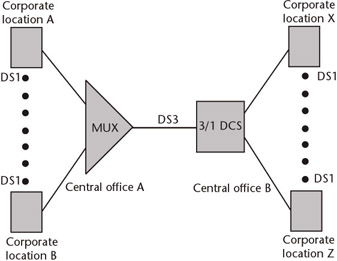
Figure 8.4: DS1 transport via a CO multiplexer and a 3/1 DCS.
Depending on the type of DCS used and the nature of the signal, the DCS may improve transmission quality by removing “jitter” from the channels. Jitter is the difference between where a pulse is and where it should be, which disrupts synchronization. Jitter is an impairment that affects the integrity of the bit stream as it moves through regenerators and switching equipment. Jitter has a variety of causes, including transmission system noise and transmission delay. A synchronous DCS regenerates and synchronizes input streams, thereby eliminating jitter. (In cases where the T1 stream itself is used to carry a synchronizing reference, however, the jitter is reproduced.) But other types of DCS based on space division switching do not have the capability of removing jitter. With these plesiochronous (nearly synchronized) systems, the transmitted signals have the same nominal digital rate but are synchronized on different clocks. This inaccuracy in timing allows the signal to be cross-connected, provided that the variation falls within strict limits.
8.9.1 Customer-Controlled Reconfiguration
Although the DCS is used in all carrier networks, these systems are used in private networks as well. In either case, the DCS groom-and-fill functions enable more efficient utilization of the available bandwidth, which helps reduce the cost of operations. But if an organization does not want to invest in infrastructure, but does want to retain control, a shared DCS can be accessed for reconfiguring bandwidth as part of a carrier service.
This arrangement is known as customer-controlled reconfiguration (CCR). Instead of waiting for service orders to be processed before they could rearrange their networks, users now have the capability to do it themselves via a terminal connected to a carrier’s central CCR control system (see Figure 8.5). Some carriers guarantee a response time to user-initiated reconfigurations, whereas other carriers make no guarantees.
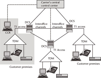
Figure 8.5: Typical CCR arrangement, whereby the corporate subscriber manages bandwidth groom-and-fill functions of the DCS network by issuing instructions to the carrier’s central control center from an on-premises terminal.
The control system is the heart of any DCS network. It communicates instructions from the user to the various cross-connect systems that will be involved in implementing the routing changes. This capability is useful for disaster recovery, for bypassing critical systems so that scheduled preventive maintenance may be performed, and for handling peak traffic demand. Each carrier’s DCS central control facility holds network routing maps for each service subscriber. With the maps held in memory, each subscriber may invoke predefined alternative configurations with only a few keystrokes from its on-premises control terminal.
The reconfiguration activity may be implemented over a dial-up connection or leased line. The changes typically take effect within 30 minutes under a basic CCR service or within 5 minutes under a premium CCR service. Although this
performance is acceptable for many scheduled applications, other methods of reconfiguring circuits, such as ISDN’s primary rate services and switching via T1 multiplexers, are better suited for implementing reconfigurations on a dynamic basis. In the case of ISDN, reconfigurations may be performed on a call-by-call basis, whereas the multiplexer may implement event-driven reconfigurations in addition to scheduled reconfigurations by time of day. A T1 multiplexer equipped with the ISDN PRI offers the highest degree of flexibility for implementing reconfigurations.
Unlike the CO switch, which sets up, supervises, and tears down communication paths every time a call is placed, the DCS allows communication paths to remain in place for continuous use over a period of months, or even years. For networks with constantly changing needs, however, circuits may be added, deleted, or rearranged as demand warrants. This capability can result in tremendous cost savings because it eliminates the tendency to overextend facilities to meet any contingency.
Further, a single cross-connect system is typically shared among many customers, allowing the telephone company to offer VPNs to small companies, many of whom appreciate the benefits of private networks but still cannot afford to implement multi-node configurations of their own. Hubbing off the CO cross-connect system makes a viable alternative to setting up a separate network because the arrangement can provide all of the control and flexibility of a private network without the huge capital investment in equipment and the risk of obsolescence.
The carrier-provided DCS service offers a high degree of configuration flexibility.-Instead of connecting all sales offices in a region via dedicated facilities, for example, a single T1 span from each site to the local CO would allow company-wide voice, data, and video communication through the telephone company’s cross-connect system, thus facilitating information flow. Via a multipoint bridge, the headquarters office can be connected to all sales offices at once for e-mail broadcasting of current price and product availability information, or for voice conferencing with branch managers. Corporate reports requiring immediate action may be batch-faxed to all locations simultaneously. Instead of gathering the regional sales force at a central location, video transmissions can relay product demonstrations and installation procedures at a fraction of the cost.
Telecommunication personnel at the company’s main office would be able to alter the circuit configurations as needed to control the cost of telecommunication. During peak hours, for example, the cross-connect may be configured to make more bandwidth available to accommodate the increase in traffic. If traffic reports indicate trends in usage by hour of day or day of week, this information can be stored in a computer. Primary, secondary, and tertiary configurations can then be uploaded to the cross-connect system with only a few keystrokes.
In addition to obtaining a suitable hub location for private networks, the DCS provides access to standby digital facilities in the event of catastrophic failure. This “bandwidth on demand” capability eliminates the need and cost for dial backup systems, which are typically configured to provide access to the public-switched network in case of deteriorating conditions or line outages. In such cases, the cross-connect enables the telephone company to bill subscribers for bandwidth actually used, providing an alternative to the uncertain line quality inherent in the public network.
For subscribers who do not have the technical expertise to put failed facilities back into service, the telephone company may access and test failed facilities to isolate the cause of the failure. For a charge, the telephone company will perform tests and verification procedures to ensure the proper operation of circuits before turning them back on for the subscriber.
Since the cross-connect system and associated services offered by carriers are typically shared among several customers, they are password protected to prevent one company from inadvertently accessing the network of another company. Passwords also protect each customer’s network from unauthorized intrusions. By being able to partition the cross-connect system in this way, carriers can provide large and small businesses with the means to control their own facilities without having to invest too heavily in a team of experts to maintain it.
Companies with expensive digital PBXs would be able to achieve even greater economies by subscribing to a telephone company’s cross-connect system. The PBX pipes all voice and data traffic directly to the CO via one or more T1 lines. Here, the cross-connect routes the individual channels to their appropriate destinations. This greatly reduces the switching burden of the PBX, especially during peak hours, while permitting its more efficient utilization for other memory-intensive call-handling features, as well as sophisticated options like voice mail.
8.9.2 Selecting a Carrier-Provided Service
To succeed in an operating environment that is steadily becoming more competitive, carriers are becoming more market-oriented, not necessarily with the idea of increasing market share, but with the idea of protecting their revenue bases against further erosion. In subscribing to a carrier-provided cross-connect service, several factors must be considered.
Any relationship with the local telephone company (or interexchange carrier) is difficult to terminate quickly when things go awry; after all, financial penalties may be exacted and potential disruption of the organization’s entire communication system may result. Therefore, companies must know the costs for both entering into and withdrawing from the arrangement. The long lead times required to plan, order, and install a cross-connect system, as well as find a suitable location for it, can make dependence on the telephone company’s service a long-term affair. To minimize risks, future problems must be anticipated by thoroughly discussing installation, maintenance, operation, and expansion issues with the telephone company.
The user should also define and agree on the telephone company’s scope and level of responsibility. For example, if the user plans to rely on the telephone company’s digital facilities as a backup link for mainframe access, some assurance must be made as to the availability of such links and what recourse is provided if a backup facility is not available when needed. Despite assurances, a telephone company or carrier cannot guarantee that it will have the capacity available to switch all of a customer’s T1 circuits to backup facilities in the event of a disaster. Even if disaster recovery swapping arrangements with other carriers over their fiber networks are in place, the company has no guarantee that it will have all the bandwidth needed when a particular customer needs it. Because the possibility exists that the telephone company’s cross-connect could suffer a catastrophic failure, potential subscribers should determine what measures have been taken to guard against that eventuality and what penalties can be invoked in case critical facilities are lost as a result of a cross-connect failure.
Some newer cross-connects used in carrier networks can automatically reconfigure around a failed link in as little as 60 ms and switch back to the restored circuit in 250 µ s. Before opting for this feature, a company must decide whether giving up this level of control is worth the risk. The risk is that the carrier may reroute to a poor-quality circuit or that some circuitous route may introduce intolerable delays that can disrupt both voice and data traffic, all of which may succeed in compounding the original problem. And when the carrier switches back to the restored circuit, the delay, however slight, may be enough to disrupt transmissions in progress.
Companies with extensive networks using the services of multiple carriers might be concerned that making direct connections to a carrier’s cross-connect system could force them to take network timing from that carrier. When using multiple carriers for dedicated circuits, each carrier may have a slightly different timing network, in which case jitter can become an issue. In most cases, however, the jitter correction features of the DCS come into play, eliminating this as a serious problem.
In subscribing to a carrier-provided DCS service, it is worthwhile to ensure that the DCS is not front-ended by a legacy M13 multiplexer at the CO. The M13 is very limited in the type of information it provides, and what it does provide is of dubious value. The M13’s best in-service measurement is a parity check, which is only 50% accurate, and can be altered as the signal is transported through the network. Fortunately, M13 change-outs have been under way for several years in favor of more intelligent cross-connects or SONET equipment, which do provide extensive and accurate performance reporting.
The carrier should provide the necessary training on the use of the management terminal. Although most cross-connect systems feature reconfiguration systems that are menu-driven, operators may take awhile getting comfortable with such systems. After all, taking responsibility for rearranging an entire network, or even a small segment, with only a few keystrokes can overwhelm anyone until they get accustomed to the idea. Determine to what extent follow-up training is available. A customer-support hotline should also be available to provide technical assistance at any time of day or night.
8.9.3 Implementing a DCS Network
Companies with large private networks might want to implement their own DCS network. To design a cross-connect network, one of the first steps is the selection of strategic nodes. It is not necessarily the physical location of the nodes that counts most but the volume of traffic and the patterns of that traffic into and out of all sites that matter most. By looking at the volume and pattern of traffic, the best decision can be made on where to locate the DCS nodes to achieve the benefits of efficiency and economy. If a large percentage of traffic is clustered around a few nodes, these will probably be the best locations for the cross-connect systems.
Some cross-connect systems have enough memory to store up to a dozen network configurations so that circuit rearrangements may be invoked automatically by time of day using an internal clock as the controlling mechanism, similar to the way large network switches activate port reconfigurations by time of day to accommodate peak loads. Some systems even have multiple levels of memory backup to protect the cross-connect maps, which typically take hours of meticulous planning to prepare. Even if power is disrupted, the map images are restored automatically from nonvolatile memory upon resumption of power.
Because of the large amount of information that the cross-connect handles at any given time, reliability is crucial. The cross-connect should have redundancy in all critical circuits, including the switching network modules, system clock and synchronization circuits, and power converters. Self-monitoring software that continually verifies system performance and facility integrity should be embedded into its design.
Cross-connect systems should have an administration terminal capable of performing a range of network management tasks including the following:
-
Facility monitoring, which enables such functions as reset slip and framing loss counters for individual connections terminated on the cross-connect (the system should monitor and automatically report the occurrence of an impending facility failure);
-
Diagnostics, to include the ability to initiate tests while circuits are in or out of service;
-
Connection service, to include the ability to set up or remove connections between individual DS0 channels or sequential groups of channels of various cross-connect modules;
-
Test access, to include defining the test ports on the cross-connect system, invoking the test-port configuration, and making or removing test connections;
-
Removal and restoration of service, which entails removing circuits from service and restoring them to service (during restoration of service, diagnostic routines should run automatically before the circuit accepts traffic);
-
Utilities, to include status reports on facility performance and system status on request;
-
System configuration, to include allowing the addition or removal of T1 interfaces and switching network modules in preparation for expanding or contracting the network or network segment.
Finally, the possibility of using smaller cross-connects in conjunction with carrier-provided DCS services should not be overlooked. This allows network elements to be organized into a two-level hierarchical arrangement, whereby several low-end cross-connects would multiplex and switch bit streams onto a backbone network controlled by only a few high-end cross-connects. This arrangement can offer greater efficiency and management control.
|
| < Day Day Up > |
|
EAN: 2147483647
Pages: 184