Parallel Ports
| Parallel ports are normally used for connecting printers to a PC. Even though that was their sole original intention, parallel ports have become much more useful over the years as a more general-purpose, relatively high-speed interface between devices (when compared to serial ports). Today, USB 1.1 compliant ports are almost as fast as parallel ports, and USB 2.0, IEEE 1394a, and IEEE 1394b ports are significantly faster. Originally, parallel ports were one way only; however, modern parallel ports can send and receive data when properly configured. Parallel ports are so named because they have eight lines for sending all the bits that comprise 1 byte of data simultaneously across eight wires. This interface is fast and traditionally has been used for printers. However, programs that transfer data between systems always have used the parallel port as an option for transmitting data because it can do so 4 bits at a time, rather than 1 bit at a time as with a serial interface. The following section looks at how these programs transfer data between parallel ports. The only problem with parallel ports is that their cables can't be extended for any great length without amplifying the signal; otherwise, errors occur in the data. Table 15.11 shows the pinout for a standard PC parallel port.
IEEE 1284 Parallel Port StandardThe IEEE 1284 standard, called Standard Signaling Method for a Bidirectional Parallel Peripheral Interface for Personal Computers, was approved for final release in March 1994. This standard defines the physical characteristics of the parallel port, including data-transfer modes and physical and electrical specifications. IEEE 1284 defines the electrical signaling behavior external to the PC for a multimodal parallel port that can support 4-bit modes of operation. Not all modes are required by the 1284 specification, and the standard makes some provision for additional modes. The IEEE 1284 specification is targeted at standardizing the behavior between a PC and an attached device, specifically attached printers. However, the specification is also of interest to vendors of parallel port peripherals (removable-media drives, scanners, and so on). IEEE 1284 pertains only to hardware and line control and does not define how software is to talk to the port. An offshoot of the original 1284 standard has been created to define the software interface. The IEEE 1284.3 committee was formed to develop a standard for software that is used with IEEE 1284compliant hardware. This standard, designed to address the disparity among providers of parallel port chips, contains a specification for supporting EPP (the Enhanced Parallel Port) mode via the PC's system BIOS. IEEE 1284 enables much higher throughput in a connection between a computer and a printer or two computers. The result is that the printer cable is no longer the standard printer cable. The IEEE 1284 printer cable uses twisted-pair technology, which results in a much more reliable and error-free connection. The IEEE 1284 standard also defines the parallel port connectors, including the two preexisting types (called Type A and Type B), as well as an additional high-density Type C connector. Type A refers to the standard DB25 connector used on most PC systems for parallel port connections, whereas Type B refers to the standard 36-pin Centronics-style connector found on most printers. Type C is a high-density 36-pin connector that can be found on some of the newer printers on the market, such as those from HP. The three connectors are shown in Figure 15.14. Figure 15.14. The three different types of IEEE 1284 parallel port connectors.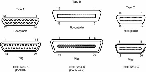 The IEEE 1284 parallel port standard defines five port-operating modes, emphasizing the higher-speed EPP and ECP modes. Some of the modes are input only, whereas others are output only. These five modes combine to create four types of ports, as shown in Table 15.12.
The 1284-defined parallel port modes are shown in Table 15.13, which also shows the approximate transfer speeds.
Each of the port types and modes is discussed in the following sections. Standard Parallel PortsOlder PCs did not have different types of parallel ports available. The only available port was the parallel port that was used to send information from the computer to a device such as a printer. The unidirectional nature of the original PC parallel port is consistent with its primary usethat is, sending data to a printer. There were times, however, when it was desirable to have a bidirectional portfor example, when it was necessary to receive feedback from a printer, which was common with PostScript printers. This could not be done easily with the original unidirectional ports. Although it was never intended to be used for input, a clever scheme was devised in which four of the signal lines can be used as a 4-bit input connection. Thus, these ports can do 8-bit (byte) output (called compatible mode) and 4-bit input (called nibble mode). This is still very common on low-end desktop systems. Systems built after 1993 are likely to have more capable parallel ports, such as bidirectional, EPP, or ECP. Standard parallel ports are capable of effective transfer rates of about 150KBps output and about 50KBps input. Bidirectional (8-bit) Parallel PortsWith the introduction of the PS/2 series of machines in 1987, IBM introduced the bidirectional parallel port. These are commonly found in PC-compatible systems today and can be designated "bidirectional," "PS/2 type," or "extended" parallel ports. This port design opened the way for true communication between the computer and the peripheral across the parallel port. This was done by defining a few of the previously unused pins in the parallel connector, and by defining a status bit to indicate in which direction information was traveling across the channel. This allowed for a true 8-bit (called byte mode) input. These ports can do both 8-bit input and output using the standard eight data lines and are considerably faster than the 4-bit ports when used with external devices. Bidirectional ports are capable of approximately 150KBps transfer rates on both output and input. Enhanced Parallel PortEPP is sometimes referred to as the Fast Mode parallel port. Intel, Xircom, and Zenith Data Systems developed and announced the EPP in October 1991. The first products to offer EPP were Zenith Data Systems laptops, Xircom Pocket LAN adapters, and the Intel 82360 SL I/O chip. Currently, almost all systems include a multimode parallel port that supports EPP mode; it's usually built into the Super I/O chip or South Bridge chip on the motherboard. EPP operates at almost ISA bus speed and offers a tenfold increase in the raw throughput capability over a conventional parallel port. EPP is especially designed for parallel port peripherals, such as LAN adapters, disk drives, and tape backups. EPP has been included in the IEEE 1284 Parallel Port standard. Transfer rates of up to 2.77MBps are possible with EPP. Since the original Intel 82360 SL I/O chip in 1992, other major chip vendors (such as National Semiconductor, SMC, Western Digital, and VLSI) have also produced I/O chipsets that offer some form of EPP capability. One problem is that the procedure for enabling EPP across the various chips differs widely from vendor to vendor, and many vendors offer more than one I/O chip. EPP version 1.7 (March 1992) identifies the first popular version of the hardware specification. With minor changes, this has since been abandoned and folded into the IEEE 1284 standard. Some technical reference materials have erroneously made reference to "EPP specification version 1.9," causing confusion about the EPP standard. Note that "EPP version 1.9" technically does not exist, and any EPP specification after the original version 1.7 is more accurately referred to as a part of the IEEE 1284 specification. Unfortunately, this has resulted in two somewhat incompatible standards for EPP parallel ports: the original EPP Standards Committee version 1.7 standard and the IEEE 1284 Committee standard, usually called EPP version 1.9. The two standards are similar enough that new peripherals can be designed to support both, but older EPP 1.7 peripherals might not operate with EPP 1284 (EPP 1.9) ports. For this reason, many multimode ports allow configuration in either EPP 1.7 or 1.9 mode, normally selected via the BIOS Setup. EPP ports are now supported in virtually all Super I/O chips that are used on modern motherboards and in South Bridge chips that integrate I/O functions. Because the EPP port is defined in the IEEE 1284 standard, it also gained software and driver support in Windows 9x/Windows NT on up. Enhanced Capabilities PortIn 1992, Microsoft and Hewlett-Packard announced the Enhanced Capabilities Port (ECP), another type of high-speed parallel port. Similar to EPP, ECP offers improved performance for the parallel port and requires special hardware logic. Since the original announcement, ECP is included in IEEE 1284just like EPP. Unlike EPP, however, ECP is not tailored to support portable PCs' parallel port peripherals; its purpose is to support an inexpensive attachment to a very high-performance printer or scanner. Furthermore, ECP mode requires the use of a DMA channel, which EPP did not define and which can cause troublesome conflicts with other devices that use DMA, such as ISA sound cards or high-performance ISA SCSI host adapters. Most PCs with newer Super I/O chips or integrated South Bridge I/O support can support either EPP or ECP mode. Most systems today that include a parallel port support ECP's high-throughput communications. In most cases, the ECP can be turned into EPP or standard parallel ports via BIOS. However, it's recommended that the port be placed in ECP mode for the best throughput. The DMA channel assignment used for ECP mode on a built-in parallel is usually performed through the BIOS setup program, but on some older systems you might need to move a jumper block on the motherboard itself. Upgrading to EPP/ECP Parallel PortsIf you want to test the parallel ports in a system, especially to determine which type they are, I highly recommend a utility called Parallel (PARA14.ZIP). This is a handy parallel port information utility that examines your system's parallel ports and reports the port type, I/O address, IRQ level, BIOS name, and an assortment of informative notes and warnings in a compact and easy-to-read display. The output can be redirected to a file for tech support purposes. Parallel uses very sophisticated techniques for port and IRQ detection, and it is aware of a broad range of quirky port features. You can get it from Parallel Technologies (www.lpt.com). If you have an older system that does not include an EPP/ECP port and you want to upgrade, several companies now offer boards with the correct Super I/O chips to implement these features. I recommend that you check with Parallel Technologies, Byterunner Technologies, Lava Computer Mfg., or SIIG; they are listed in the Vendor List on the disc accompanying this book. Although USB ports are replacing most nontraditional parallel port uses, high-speed parallel ports such as EPP and ECP are still used for supporting external peripherals, such as Zip drives, CD-ROM drives, scanners, tape drives, and even hard disks. Most of these devices attach to the parallel port using a pass-through connection. This means your local printer can still work through the port, along with the device. The device will have its own drivers that mediate both the communications with the device and the printer pass-through. Using EPP or ECP mode, communications speeds that are as high as 2.77MBps can be achieved. This can enable a relatively high-speed device to function almost as if it were connected to the system bus internally. Parallel Port ConfigurationThe configuration of parallel ports is not as complicated as it is for serial ports. Even the original IBM PC had BIOS support for three LPT ports. Table 15.14 shows the standard I/O address and interrupt settings for parallel port use.
Because the BIOS and DOS have always provided three definitions for parallel ports, problems with older systems are infrequent. Problems can arise, however, from the lack of available interrupt-driven ports for ISA/PCI bus systems. Usually, an interrupt-driven port is not absolutely required for printing operations; in fact, many programs do not use the interrupt-driven capability. However, some programs do use the interrupt, such as network print programs and other types of background or spooler-type printer programs. Also, high-speed laser-printer utility programs often use the interrupt capabilities to enable printing. If you use these types of applications on a port that is not interrupt driven, you see the printing slow to a crawlif it works at all. The only solution is to use an interrupt-driven port. MS-DOS and Windows 9x/Me/2000/XP now support up to 128 parallel ports. To configure parallel ports in ISA/PCI bus systems, you normally use the BIOS Setup program for ports that are built into the motherboard, or you might need to set jumpers and switches or use a setup program for adapter-card-based ports. Because each board on the market is different, you always should consult the OEM manual for that particular card if you need to know how the card should be configured.
Linking Systems with Serial or Parallel PortsYou can connect two systems locally using their serial or parallel ports along with specially wired cables. This form of connection has been used over the years to enable a quick and easy mini-LAN to be set up that allows for the transfer of data between two systems. This can be especially useful when you are migrating your data to a new system you have built or purchased. Even though using serial or parallel ports to connect two systems to migrate data can be useful, a much better way to connect two systems is to use Ethernet cards and what is commonly called a crossover cable. Using this type of connection, you can establish a LAN connection between the two systems and transfer data at the full speed of the Ethernet network, which is 10Mbps, 100Mbps, or 1,000Mbps (1.25MBps, 12.5MBps, or 125MBps). Using serial or parallel ports to transfer data between two systems was more prevalent when most systems did not include some form of network interface card (NIC). Several free and commercial programs can support serial or parallel-port file transfers. MS-DOS 6.0 and later include a program called Interlink, whereas Windows 95 and later include software called either Direct Cable Connection or Direct Parallel Connection. Other commercially available software includes Laplink.com's LapLink series, Smith Micro's CheckIt FastMove, and Symantec's PC Anywhere, among others. Serial Port TransfersSerial ports have always been used for communications between systems, but the ports were usually connected to modems that convert the data to be transmitted over telephone lines, enabling long-distance connections. If the systems were in the same room, you could connect the serial ports directly without using modems by instead using what is commonly referred to as a null modem cable. The name comes from the fact that there really aren't any modems presentthe cable effectively replaces the modems that would be used at either end. The only drawback is that, because serial ports evolved to support relatively low-speed modem communications, even when using a null modem cable, the connection would be slow because most ports can transmit at 115.2Kbps (14.4KBps). By using a null modem cable, serial ports can be used to transfer data between systems, although the performance is much lower than when using parallel ports. A serial null modem cable has either a 9-pin or a 25-pin female connector on both ends. The cable should be wired as shown in Table 15.15.
If both systems feature infrared serial ports, you can connect the two systems via an infrared connection that uses no cable at all. This type of connection is subject to the limitations of the infrared ports, which allow only very short (a few feet at most) distances with fairly slow data rates. Because they work so slowly, I usually recommend using serial ports to transfer data between two systems only as a last resort. If possible, you should try to use Ethernet cards and a crossover cable, a USB direct connect cable, or parallel ports with an interlink cable for faster connections. Parallel Port TransfersAlthough the original intention for the parallel port was for it to be used to connect a printer, later implementations allowed for bidirectional data transfer. Bidirectional parallel ports can be used to quickly and easily transfer data between one system and another. If both systems use an EPP/ECP port, you can actually communicate at rates of up to 2.77MBps, which is far faster than the speeds achievable with serial port or infrared (IR) data transfers. Connecting computers with parallel ports requires a special cable known as a Direct Cable Connection (DCC), Interlink, LapLink, parallel crossover, or parallel null modem cable. Many of the commercial file transfer programs provide these cables with their software, or you can purchase them separately from most computer stores or companies that sell cables. However, if you need to make one for yourself, Table 15.16 provides the wiring diagram you need.
Tip Even though cables usually are provided for data-transfer programs, notebook users might want to look for an adapter that makes the appropriate changes to a standard parallel printer cable. This can make traveling lighter by preventing the need for additional cables. A DB25 null modem adapter, such as Belkin's F4A602, can be used for this purpose. Although the prebuilt parallel cables referred to in the previous tip work for connecting two machines with ECP/EPP ports, they can't take advantage of the advanced transfer rates of these ports. Special cables are needed to communicate between ECP/EPP ports. Parallel Technologies is a company that sells ECP/EPP cables for connecting to other ECP/EPP computers, as well as a universal cable for connecting any two parallel ports to use the highest speed. Windows 9x/Me include a special program called Direct Cable Connection or Direct Parallel Connection, which enables two systems to be networked together via a parallel transfer cable. With Windows 2000 and XP, use the Network Connections dialog box to set up a direct connection. Consult the Windows documentation for information on how to establish a DCC/Direct Parallel connection. Parallel Technologies has been contracted by Microsoft to supply the special DCC cables used to connect the systems, including a special type of cable that uses active electronics to ensure a reliable high-speed interconnection. Parallel-to-SCSI ConvertersParallel ports can also be used to connect SCSI peripherals to a PC. With a parallel-to-SCSI converter, you can connect any type of SCSI devicesuch as hard disks, CD-ROM drives, tape drives, Zip drives, or scannersto your PC, all via the parallel port. To connect to a SCSI device and also continue to be able to print, most parallel-to-SCSI converters include a pass-through connection for a printer. Therefore, at one end of the converter is a connection to your parallel port, and at the other end is both SCSI and parallel-port connections. Thus, you can plug in a single SCSI device and still connect your printer as well. The drivers for the parallel-to-SCSI converter automatically pass through any information to the printer, so the printer works normally. Some of these converters handle only one SCSI device, but others can handle up to seven SCSI devices, just as normal SCSI host adapters do. SCSI devices are much slower when connected to a parallel port than when they are connected to a native SCSI host adapter. Testing Parallel PortsTesting parallel ports is, in most cases, simpler than testing serial ports. The procedures are effectively the same as those used for serial ports, except that when you use the diagnostics software, you (obviously) select choices for parallel ports rather than serial ports. Even though the software tests are similar, the hardware tests require the proper plugs for the loopback tests on the parallel port. Several loopback plugs are required, depending on what software you are using. Most use the IBM-style loopback, but some use the style that originated in the Norton Utilities diagnostics. You can purchase loopback plugs or build them yourself. The following wiring is needed to construct your own parallel loopback or wrap plugs to test a parallel port:
|
EAN: 2147483647
Pages: 283