Embedded and Integrated Components
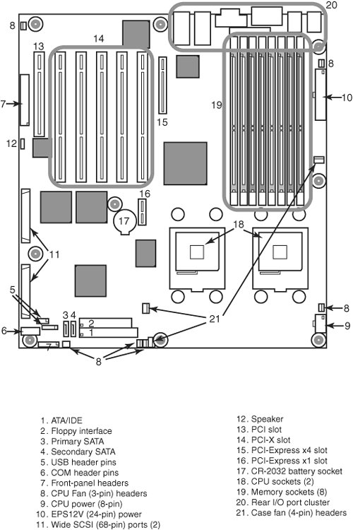
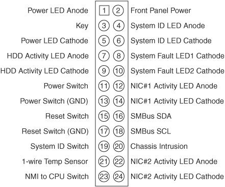
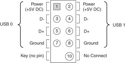
| There are a variety of connectors on a modern motherboard. Figure 4.36 shows connector locations on a typical motherboard. Note that Figure 4.36 combines features from several different motherboards; you might not see every feature on a particular motherboard. Several of these connectors, such as power supply connectors, serial and parallel ports, and keyboard/mouse connectors, are covered in other chapters. Figure 4.36. Typical motherboard connectors on a dual-processor server. This section provides figures and tables that show the configurations and pinouts of most of the other interface and I/O connectors you will find. One of the biggest problems many people overlook when building and upgrading systems is the front panel connections. Connectors that don't match between the motherboard and chassis are one of the small but frustrating things that can be problematic in an otherwise smooth upgrade or system build. Unfortunately, there is no single standard in use for front panel connectors on servers. The de facto standard for front panel connections in servers is the SSI front panel I/O connector shown in Figure 4.37. Motherboards that fully adhere to one of the current SSI standards (CEB, EEB, and TEB) use this I/O connector. Note that this I/O connector is often located on the left edge of the motherboard, as viewed from the front, rather than on the front edge, as with many desktop motherboards. Figure 4.37. Front panel connections specified by SSI server standards. This is a much larger connector than the 10-pin keyed header defined by the "Intel Front Panel I/O Connectivity Guide" first developed in 2000 and followed by Intel and some other desktop PC makers. The SSI front panel connector supports additional LEDs used for system faults, activity and fault lights for up to two onboard NICs, temperature sensor, system ID, NMI, SMBus, and chassis intrusion. These features are very important for server management. Most current Intel server motherboards use the SSI connector. Other major brands of server motherboards, however, use different connector standards, and sometimes a single brand of server uses more than one front panel connector standard on different models. See the manual for a particular server or server motherboard to determine the pinout and features supported. Tip If your server uses SATA drives connected to an add-on card rather than the motherboard's integrated host adapter, the front drive access light will not operate. This light is normally connected to pins 7 and 9 of the SSI front panel connections shown in Figure 4.37 or to the equivalent pins on servers that use a different front panel connection standard. To enable the HDD activity light to operate when SATA drives connected to an add-on card are in use, connect the HDD activity light to the SATA adapter card, if possible. See the documentation for your server's SATA host adapter card to determine whether the card has a connector for HDD activity lights. To adapt the connectors in a chassis to those on a motherboard, in some cases you might need to change the connector ends by removing the terminals and reinserting them into different positions. For example, in a chassis that uses a 3-pin power LED connection and a motherboard with only a 2-pin connection, you have to remove one of the terminals, reinsert it into the middle position on the 3-pin connector, and then plug the connector in to the motherboard so that two pins are mated and the third empty position is hanging off the end of the connector. Fortunately, the terminals are easy to remove by merely lifting a latch on the side of the connector and then sliding the terminal and wire back out. When the terminal is inserted, the latch automatically grabs the terminal and locks it into position. To minimize the need to adapt connectors, you should use a chassis recommended by your server motherboard vendor. Many server motherboards include front panel USB connectors, which are designed to be connected to front-mounted USB connectors in the chassis. The standard uses a single 10-pin keyed connector to provide two USB connections. The pinout of a standard dual USB motherboard header connector is shown in Figure 4.38 and Table 4.17. Figure 4.38. Front panel dual-USB header connector configuration.
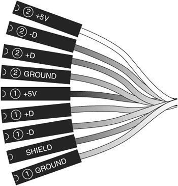
Many chassis includes multiple inline connectors for the dual-USBtofront panel connection instead of a single keyed connector. An example of this is shown in Figure 4.39. Figure 4.39. Front panel USB cable using multiple individual non-keyed connectors. Using the multiple individual connectors shown in Figure 4.39, you would have to plug each individual connector in to the proper pin. Some internal chassis USB cables use two 5-pin inline connectors, in which case you just need to ensure that you don't put them on backward. You should consult your motherboard and chassis manual for more information if you are unsure about your particular connections. Caution If your chassis uses multiple individual non-keyed connections, you must be sure to connect them properly to the connector on the motherboard. If you connect them improperly, you can cause a short circuit to occur that can damage the motherboard or any USB peripherals you plug in to the front panel connectors. Higher-quality motherboards usually have self-healing fuses on the power signals, which can prevent damage if such a situation occurs. You might want to tape the cables together before inserting them to keep them in the right sequence. Other miscellaneous connectors might appear on server motherboards as well; several are shown in Table 4.184.24.
Most modern server motherboards have five or more fan connectors for use with the processor fan(s), rear chassis fan, front chassis fan, and voltage regulator (power) fan(s) (see Tables 4.25 and 4.26). They all generally use the same 3-pin connector, with the third pin providing a tachometer signal for optional speed monitoring. If the motherboard is capable of monitoring the fan speed, it can sound an alarm when the fans begin to slow down due to bearing failure or wear. The alarm sound can vary, but it normally comes from the internal speaker and might be an ambulance sirentype sound. Some systems use both 3-pin and 4-pin fan connectors; the extra pin provides support for pulse width modulation (PWM) fan speed control via the system BIOS, enabling the fan to run faster or slower, as needed, to provide adequate system cooling.
Note that pins 1 through 3 of the 4-pin fan headers in Table 4.26 are the same as the pinouts in Table 4.25. Even though some motherboards have both types of fan headers (see Figure 4.36 for an example), you should use all the same type of fan if you enable thermal management control in the system BIOS. Caution Do not place a jumper on the fan connector; serious board damage will result if the 12V is shorted to ground. SCSI, ATA/IDE, and SATAUnlike desktop PCs, which use primarily ATA/IDE or SATA interfaces for hard disks, most servers use SCSI interfaces for hard disks, including RAID arrays. As a result, a typical server may feature one or two 68-pin SCSI connectors on the motherboard, with corresponding SCSI host adapter chips. Servers use ATA/IDE host adapters primarily for optical (CD, DVD) drives. Depending on the chipset, ATA/IDE host adapters might run at typical UDMA speeds up to UDMA-100 or UDMA-133, or they might run at much slower PIO speeds. Some recent servers use SATA ports in place of SCSI ports. In most cases, the SATA ports can be operated in a RAID 0 (striping) or RAID 1 (mirroring) configuration. If four SATA ports (and drives) can be connected to the motherboard, RAID 0+1 can be used for speed and safety. Some servers also support the new SAS (Serial Attached SCSI) standard, which supports both SAS and SATA drives. The configuration of ATA/IDE and SATA host adapters on a server motherboard is performed through the system BIOS. Depending on the motherboard, SCSI and SAS host adapters might be enabled or disabled via the system BIOS or via jumpers on the motherboard. Note that the system or option BIOS is used to configure SATA or SCSI drives in a RAID array and to configure SCSI settings. If SATA, SCSI, or SAS drives are supported by an add-on adapter, the adapter's BIOS is used to configure the interface and drives.
NICs, Modems, and Wireless NICsDepending on the server, a network adapter (NIC) might be plugged in to a PCI, PCI-X, or PCI-Express x1 slot or might be located on the motherboard. Older servers with integrated NICs usually feature a 10/100 Ethernet RJ-45 port, while current servers with integrated NICs might feature a 10/100/1000 Ethernet RJ-45 port. Servers with two NIC ports can be used as routers without the addition of an additional NIC. Although wireless networks using the IEEE 802.11 (Wi-Fi) family of standards are extremely common, there are virtually no servers with integrated wireless Ethernet NICs. Dial-up modems are also quite scarce on servers. Although servers designed for communications might feature one or more RJ-11 telephone jacks, these are normally used for connections to telephone switches rather than by analog modems. Legacy Ports (Serial, Parallel, Keyboard, and Mouse)Although legacy ports (serial, parallel, PS/2 keyboard, and PS/2 mouse) are fading away in current desktop and notebook computer designs, these ports are still virtually universal in server designs. There are several reasons for the continued popularity of legacy ports:
Note that some server systems and motherboards omit the parallel port but usually include the other legacy ports listed here. Servers that use ATX or other ATX-derived motherboard form factors provide access to legacy ports via the port cluster at the rear of the motherboard. PICMG-based single-board computers might place some legacy ports on the rear bracket, while others might be located on header cables. Although proprietary server designs vary in their legacy port locations, virtually all of them place the legacy ports at the rear of the system. USB and IEEE 1394USB ports are quite common on servers, but the level of USB support varies by server. Older servers might support USB 1.1 devices only, while most recent servers also support USB 2.0 devices. If you plan to use USB input devices (mouse and keyboard), you need to be sure to verify that USB legacy support is available and enabled in the system BIOS. See "CMOS Settings and Specifications," later in this chapter, for details. Although most recent and current servers support USB 2.0 devices, most servers do not support USB devices such as floppy or flash memory drivers as boot devices. If your system does not support USB drives as boot devices and you plan to use floppy diskbased diagnostic or testing software, you should specify a traditional floppy-controllerbased 1.44MB floppy drive as part of your server's configuration or use bootable CD-based diagnostic and testing programs. To determine whether your server can boot from a USB drive, check the server's BIOS configuration. Although USB ports are common on servers, the only servers that incorporate IEEE 1394 ports are Macintosh servers. Servers can use IEEE 1394 ports for high-speed external storage. |
EAN: 2147483647
Pages: 240