ROM BIOS
| BIOS stands for basic input/output system, and it consists of low-level software that controls the system hardware and acts as an interface between the operating system and the hardware. Most people know the term BIOS by another name: device drivers, or just drivers. In other words, the BIOS is a collection of all the drivers in a system. BIOS is essentially the link between hardware and software in a system. The system BIOS is contained in a ROM chip on the motherboard that also contains the power-on self-test (POST) program and a bootstrap loader. The BIOS directs the bootstrap loader to look for an operating system (OS) in any one of various drive locations. After the OS was loaded, the bootstrap program could call on the low-level routines (device drivers) in the BIOS to interact with the system hardware. Motherboard BIOSEvery server with an x86 or Itanium processor must have a special chip that contains software called the ROM BIOS. This ROM chip contains the startup programs and drivers used to get the system running and act as the interface to the basic hardware in the system. When you turn on a system, the POST in the BIOS also tests the major components in the system. In addition, you can run a setup program to store system configuration data in the CMOS memory, which is powered by a battery on the motherboard. This CMOS RAM is often called NVRAM because it runs on about 1 millionth of an amp of electrical current and can store data for years when powered by a tiny lithium battery. The BIOS is a collection of programs embedded in one or more chips, depending on the design of the computer. That collection of programs is the first thing loaded when you start the computer, even before the operating system. The BIOS in most x86 and Itanium servers has four main functions:
The system ROM BIOS is loaded into upper memory (that is, memory between 640KB and 1MB) when the system is started, as are BIOS chips on the video adapter and other adapter ROM BIOS chips used in the system. Figure 4.40 shows a map of the first megabyte of memory in a PC; notice that the upper memory areas are reserved for adapter card and motherboard RAM or ROM BIOS at the end of the first megabyte. Figure 4.40. PC memory map showing ROM BIOS.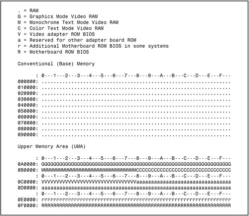 If you are working with legacy (ISA/EISA) hardware that uses RAM or ROM BIOS chips, you need to make sure each device that uses RAM or ROM uses a non-overlapping section of upper memory. PnP hardware, BIOS, and operating systems automatically place RAM and ROM chips into nonconflicting memory addresses. ROM BIOS HardwareThe main ROM BIOS is contained in a ROM chip on the motherboard, but adapter cards with ROMs contain auxiliary BIOS routines and drivers needed by the particular card, especially for cards that must be active early in the boot process, such as video cards. Cards that don't need drivers active during boot (such as sound cards) typically don't have ROM because those drivers can be loaded from the hard disk later in the boot process. Because the BIOS is the main portion of the code stored in ROM, we often call the ROM the ROM BIOS. Adapter card ROMs, such as those used for video, SCSI, add-on ATA cards, and network cards for diskless workstations, are automatically scanned and read by the motherboard ROM during the early part of the boot processduring the POST. The motherboard ROM scans a special area of RAM reserved for adapter ROMs (addresses C0000DFFFFh), looking for 55AAh signature bytes, which indicates the start of a ROM. All adapter ROMs must start with 55AAh; otherwise, the motherboard won't recognize them. The third byte indicates the size of the ROM in 512-byte units called paragraphs, and the fourth byte is the actual start of the driver programs. The motherboard ROM uses the size byte for testing purposes. The motherboard ROM adds all the bytes in the ROM and divides the sum by the number of bytes. The result should produce a remainder of 100h. Thus, when creating a ROM for an adapter, a programmer typically uses a "fill" byte at the end to get the checksum to come out right. Using this checksum, the motherboard tests each adapter ROM during the POST and flags any that appear to have been corrupted. The motherboard BIOS automatically runs the programs in any adapter ROMs it finds during the scan. You see this in most systems when you turn on the system, and during the POST you see the video card BIOS and other BIOS chips, such as SATA, ATA/SATA RAID, and SCSI, initialize and display onscreen messages. ROM ShadowingROM chips, by their nature, are very slow, with access times of 150ns (nanoseconds, or billionths of a second), compared to DRAM access times of less than 10ns on the newest systems. Because of this, in virtually all systems, the ROMs are shadowed, which means they are copied into DRAM chips at startup to allow faster access during normal operation. The shadowing procedure copies the ROM into RAM and then assigns that RAM the same address as the ROM originally used, disabling the actual ROM in the process. This makes the system seem as though it has ROM running at the same speed as RAM. The performance gain from shadowing is often very slight, and it can cause problems if it is not set up properly. Therefore, in most cases, it is wise to shadow only the motherboard (and maybe the video card BIOS) and leave the others alone. Typically, shadowing is useful only when running 16-bit operating systems, such as DOS or Windows 3.x. When running a 32-bit or 64-bit operating system, such as Windows Server 2000, Windows Server 2003, or Linux, shadowing is virtually useless because those operating systems do not use the 16-bit ROM code while running. Instead, those operating systems load 32-bit or 64-bit drivers into RAM, which replace the 16-bit BIOS code used only during system startup. Shadowing controls are found in the CMOS Setup program in the motherboard ROM, which is covered in more detail later in this chapter. EEPROM/Flash ROMFor over a decade, virtually all x86-based servers have used a BIOS chip with EEPROM or flash ROM technology. These chips can be erased and reprogrammed with software, unlike older technologies that required the chip to be removed from the motherboard for replacement or reprogramming. If your server is having problems with hardware controlled by the BIOS, such as processor or memory upgrades, onboard ports or expansion slots, check with the system or motherboard manufacturer to see if a BIOS upgrade is available and if it solves the problems the server is experiencing. Caution Even if a BIOS upgrade is available for your server, don't install it blindly. Keep in mind that BIOS upgrades can cause problems as well as solve them. If possible, test the BIOS upgrade on a non-production server before upgrading other servers of the same type. Be sure to follow the manufacturer's instructions for performing the BIOS upgrade. A failed BIOS upgrade will prevent your system from working.
Many other devices have flash ROMs; for example, you can update the flash ROM code (often called firmware) in network routers (which act as DHCP servers and frequently run Linux), wireless access points, rewritable CD and DVD drives, and even some digital cameras. Installing flash ROM or firmware upgrades is as easy as downloading a file from the device manufacturer's website and running the update program included in the file. Flash ROM updates can also be used to add new capabilities to existing peripherals, such as modems and rewriteable DVD or CD drives, to meet the latest standards; for example, you can update a modem from X2 or K56Flex to V.90 or V.92 or add support for the latest types of media to a rewriteable drive. BIOS TypesThe system ROM BIOS is not the only BIOS chip found in a typical server. The following sections briefly discuss additional BIOS chips and BIOS types and how they work. PnP BIOSTraditionally, installing and configuring devices in PCs has been a difficult process. During installation, the user is faced with the task of configuring the new card by selecting the IRQ, I/O ports, and DMA channel. In the past, users were required to move jumpers or set switches on the add-in cards to control these settings. They needed to know exactly which resources were already in use so they could find a set of resources that did not conflict with the devices already in the system. If a conflict existed, the system might not boot, and the device might fail or cause the conflicting hardware to fail. PnP technology is designed to prevent configuration problems and provide users with the capability to easily expand a PC. With PnP, the user simply plugs in the new card, and the system configures it automatically for proper operation. PnP is composed of three principal components:
The PnP BIOS initiates the configuration of the PnP cards during the bootup process. If the cards were previously installed, the BIOS reads the information from ESCD, initializes the cards, and boots the system. During the installation of new PnP cards, the BIOS consults the ESCD to determine which system resources are available and needed for the add-in card. If the BIOS is capable of finding sufficient available resources, it configures the card. However, if the BIOS is incapable of locating sufficient available resources, the PnP routines in the operating system complete the configuration process. During the configuration process, the configuration registers (in flash BIOS) on the card and the ESCD are updated with the new configuration data. PnP Device IDsEvery PnP device must contain a PnP device ID to enable the operating system to uniquely recognize the device so it can load the appropriate driver software. Each device manufacturer is responsible for assigning the PnP ID for each product and storing it in the hardware. Each manufacturer of PnP devices is assigned an industry-unique, three-character vendor ID. The device manufacturer is responsible for assigning a unique product ID to each individual product model. After an ID is assigned to a product model, it must not be assigned to any other product model manufactured by the same company (that is, one that uses the same vendor ID). ACPIACPI, which stands for Advanced Configuration and Power Interface, defines a standard method for integrating power management as well as system configuration features throughout an x86 or Itanium server, including the hardware, operating system, and application software. ACPI goes far beyond the previous standard, called Advanced Power Management (APM), which consists mainly of processor, hard disk, and display control. ACPI controls not only power but also all the PnP hardware configuration throughout the system. With ACPI, system configuration (PnP) as well as power management configuration is no longer controlled via the BIOS Setup; it is controlled entirely within the operating system instead. ACPI enables system designers to implement a range of power management features with various hardware designs while using the same operating system driver. ACPI also uses the PnP BIOS data structures and takes control over the PnP interface, providing an operating-systemindependent interface for configuration and control. ACPI is supported by Windows 2000 Server, Windows 2003 Server, and Linux. During the system setup and boot process, Windows versions that support ACPI perform a series of checks and tests to determine whether the system hardware and BIOS support ACPI. If support for ACPI is either not detected or found to be faulty, the system typically reverts to standard APM control, but problems can also cause a lockup with a blue screen with an ACPI error code. The ACPI error codes are described in Table 4.27.
Virtually all these errors are the result of partial or incomplete ACPI implementations or incompatibilities in either the BIOS or device drivers. If you encounter any of these errors, you should contact your motherboard manufacturer for an updated BIOS or the device manufacturers for updated drivers. However, ACPI problems don't always trigger error messages. If your server won't come out of standby mode, make sure the option Allow This Device to Bring the Computer Out of Standby is enabled in the Power Management tab of the Device Manager properties sheet for devices such as network adapters, keyboards, and mouse devices. With a network adapter, you should also enable the option Allow the Computer to Turnoff This Device to Save Power if the network adapter does not work properly after the server does not come out of standby mode. Do not select the Only Allow Management Stations option on a server. Enabling this option prevents the server from responding to requests from clients if the server goes into standby mode (see Figure 4.41). Figure 4.41. Configuring a network adapter so it will wake a server from standby mode.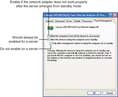 Initializing a PnP DeviceOne responsibility of a PNP BIOS during POST is to isolate and initialize all PnP cards and assign each a valid card select number (CSN). After CSNs are assigned, the system BIOS can then designate resources to the cards. The BIOS is responsible only for the configuration of boot devices; all the remaining PnP devices can be configured dynamically by the operating system software. The following steps outline a typical flow of a PnP BIOS during the POST:
If the loaded operating system is PnP compliant, it takes over management of the system resources. Any unconfigured PnP devices are configured by the appropriate system software or the PnP operating system. At this point, the operating system is loaded and takes control over PnP system resources. Using the Device Manager in the operating system, the user can control any PnP devices. Although PnP is often thought of as a Windows-specific technology, PnP configuration and device management are also performed by recent Linux distributions. Other BIOS ChipsThe PnP BIOS is built in to the system BIOS. However, other types of devices are supported by separate BIOS chips. If the device is built in to the motherboard, the BIOS chip is also located on the motherboard. If the device plugs in to a card slot, the BIOS chip is located on the card. These BIOS chips are mapped to the system's memory map at various locations between 640KB and 1MB. Typical device BIOS chips include the following:
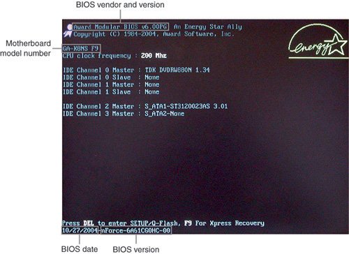
Note With Windows 2000 Server and Windows 2003 Server, you must load a driver during installation to enable most types of motherboard-based and all types of add-oncard RAID to operate. This is also required for support of SCSI host adapters. For details, see the section "ATA/SATA RAID Configurations for Server Platforms" in Chapter 6, "The ATA/IDE Interface." System Management FeaturesServers often need to be managed remotely, and IT staff need to determine when a server has problems before those problems cause a server to fail. As a result, several types of server management have been developed. Many servers support System Management Bus (SMBus) management, developed by Intel in 1995 and based on an earlier Philips standard known as I2C. SMBus uses a two-wire serial-signaling connection to transmit information about temperature, intrusion detection, and battery charge to an external monitor. SMBus version 1.x was designed to support motherboard-based devices. However, SMBus version 2.x also supports add-on cards. Many recent servers now support a newer, more advanced type of cross-platform system management standard known as the Intelligent Platform Management Interface (IPMI), which was developed by Intel, Hewlett-Packard, Dell, and NEC in 1999. IPMI enables server status and management to occur, whether a server is running or shut down. Starting with version 1.5, IPMI can use direct serial, network, or serial over network connections for management and alert messages. IPMI incorporates SMBus signaling and sensors, and it interfaces with existing SMBus host controllers to permit the existing SMBus management infrastructure to continue to be used. To learn more about SMBus, see the System Management Interface Forum, website, at www.smbus.com. To learn more about IPMI, see the Intel IPMI website, at www.intel.com/design/servers/ipmi/. Intel's Advanced Server Management Interface (ASMI) is a 120-pin motherboard connector that supports integrated KVM over IP for remote server management and other features. ASMI supports the IPMI management standard. Some server and KVM vendors such as Avocent (www.avocent.com) and Raritan (www.raritan.com) are using ASMI or proprietary daughtercards to add KVM support to existing and forthcoming servers. BIOS ManufacturersSeveral popular BIOS manufacturers in the market today supply the majority of motherboard and system manufacturers with the code for their ROM chips. This section discusses the various available versions. The leading manufacturers of server BIOS today include American Megatrends (AMI) and Phoenix Technologies. Phoenix also owns Award Software. The current Phoenix First BIOS software is based on Award BIOS version 6.x, and the current Phoenix First BIOS Pro software is based on Phoenix BIOS version 4.x. There are various ways to determine what BIOS brand and version is being used by a particular server or server motherboard:
Note that because of BIOS customization, BIOS upgrades are provided by the system or motherboard vendor or by third-party companies specializing in BIOS upgrades, not by the original BIOS vendor. If you need to troubleshoot a server, it's important to know the BIOS vendor and version number of the BIOS used by that server. Error codes and messages vary by BIOS vendor, and different versions of a BIOS for a particular server may affect compatibility. If you prefer the features and error reporting functions of a particular BIOS vendor, you may prefer to specify systems or motherboards that use your favorite BIOS. Table 4.28 lists the BIOS vendors used by a selection of current x86 and Itanium-based server motherboards made by Intel and other major vendors.
For more information about Phoenix and Award BIOS, visit www.phoenix.com. For more information about AMI BIOS, visit www.ami.com. Tip If you support servers and clients that use several BIOS types, consider adding Phil Croucher's The BIOS Companion to your bookshelf or PDF file collection. This book provides detailed BIOS options and configuration information for today's leading BIOS. You can purchase various editions from Amazon.com and other bookstores, but for the most up-to-date (and least expensive) edition, I suggest ordering the PDF (Adobe Acrobat) version of The BIOS Companion from Electrocution.com. Accessing the Motherboard BIOSIf you want to run the BIOS Setup program, you usually have to reboot the system and press a particular key or key combination during the POST. Normally, the correct key to press is displayed onscreen momentarily during the POST. If it flashes past too quickly to read, you can try pressing the Pause key on the keyboard when it appears. This freezes the system, allowing you to read the display. Pressing any other key (such as the spacebar) un-pauses the system and allows the POST to continue. The major vendors have standardized the following keystrokes to enter the BIOS Setup in recent systems:
If your system does not respond to one of these common keystroke settings, you might have to contact the manufacturer or read the system documentation to find the correct keystrokes. The following are some unique keystrokes:
When you are at the BIOS Setup main screen, you usually find a main menu that allows access to other menus and submenus of different sections or screens. The following sections cover typical BIOS menus and submenus found on typical servers running Intel or AMD processors. Even if you are familiar with the BIOS settings used on typical desktop computers, the following sections will be useful to you because servers often feature different settings than those used on desktop computers. CMOS Settings and SpecificationsAfter you enter the BIOS (CMOS) Setup menu, you can view current system settings and configuration and make changes to most settings. Some BIOS Setup listings are read-only, such as current fan RPM and motherboard/processor voltage readouts. BIOS Setup MenusMost modern BIOSs offer a menu bar at the top of the screen when you're in the BIOS Setup that controls navigation through the various primary menus. A typical menu bar offers the choices shown in Table 4.29.
Note Because most common server BIOSs use similar settings but the exact order and features vary, the following tables focus on the setup programs used by an Intel Xeon-based server and an AMD-based Opteron server. Because the BIOS is customized by the motherboard manufacturer, even the same BIOS can offer different options for different boards. The settings covered here help you get a general idea of the type of settings to expect and how the BIOS Setup settings affect your server's operation. Choosing each of these selections takes you to another menu with more choices. The following sections examine the choices available in a typical server motherboard. The Main MenuThe standard CMOS Setup menu dates back to the 286 days, when the complete BIOS Setup consisted of only one menu. In the standard menu, you can set the system clock and record hard disk and floppy drive parameters and the basic video type. Newer BIOSs have more complicated setups with more menus and submenus, so the main menu is often fairly sparse compared to those in older systems. The main menu in a modern system reports system information such as the BIOS date and version, the processor type and speed, and the amount of memory. The main menu can also be used to set the system date and time. Table 4.30 shows a typical main menu.
Some systems report a single value for installed memory, whereas others provide a separate display for extended memory. (Extended memory is the memory beyond the first megabyte in the system.) You can't change any values in the memory fields; they are only for your information because they are automatically counted up by the system. If the memory count doesn't match what you have installed, a problem has likely occurred with some of the memory: It is defective, is not fully seated or properly installed, or is a type that is incompatible with your system. Most server BIOSs have one or more beep codes that alert you to memory problems. The Advanced MenuThe Advanced menu is a doorway to submenus for setting advanced features that are available through the motherboard chipset. This part of your BIOS Setup is specific to the particular chipset the motherboard uses. Many chipsets are available on the market today, and each has unique features. The chipset setup is designed to enable the user to customize these features and control some of the chipset settings. Table 4.31 shows the typical Advanced submenus available.
The following sections discuss these options. Note that different systems might list these options in different orders or might omit or combine some submenus. The Processor and Hammer Configuration SubmenusTable 4.32 lists settings used by a typical Processor Configuration submenu used by a server running an Intel chipset and processor.
If your server uses AMD Opteron processors, you're likely to see a Hammer Configuration submenu (Table 4.33) instead of the Processor Configuration submenu.
Advanced ECC Memory Configuration SettingsServers that feature ECC memory error correction offer an option to enable or disable ECC. More advanced types of error correction require additional BIOS options. Table 4.34 lists typical ECC and advanced ECC BIOS settings. Depending on the server, these options might be found in various menus or submenus.
The I/O Device Configuration SubmenuThe I/O Device Configuration submenu is used to configure legacy I/O devices built in to the motherboard, such as serial ports, parallel ports, and sometimes others. Note that some motherboards place these options on two or more submenus. Table 4.35 shows a typical I/O Device Configuration submenu's options.
The Integrated Device Configuration SubmenuThe Integrated Device Configuration submenu is used to configure newer I/O devices built in to the motherboard, such as USB ports, SATA ports, RAID arrays, and integrated NIC boot ROMs. Note that some motherboards place these options on different menus, such as the Advanced menu or the USB Configuration submenu. Table 4.36 shows settings for typical Integrated Device Configuration submenu options.
The USB Configuration SubmenuSome systems use the USB Configuration submenu to configure USB ports and devices. When present, this submenu might also contain a submenu used to configure specific USB mass-storage devices. Table 4.37 lists typical options from a USB Configuration submenu, and Table 4.38 lists typical USB mass storage configuration settings.
The PCI Configuration SubmenusThe PCI Configuration submenus are used to configure PCI slots, to configure onboard PCI devices such as video, and to set aside hardware resources needed by legacy ISA devices. Hardly any systems have all the options shown in Table 4.39.
Table 4.40 lists typical options for setting aside resources needed by legacy ISA devices.
To make IRQs 3, 4, and 7 available, if needed, for PCI or other PnP devices you disable the serial ports (IRQs 3 and 4) and the parallel port (IRQ 7) if these ports are not used. The ATA (IDE) Hard Disk Drive Configuration SubmenuYou use the ATA Configuration submenu for configuring ATA and SATA devices, such as hard drives, CD-ROM drives, LS-120 (SuperDisk) drives, tape drives, and so on. Table 4.41 shows typical ATA Configuration submenu options for a typical modern server motherboard. Note that depending on the system, these options might be found on different menus.
The hard disk predelay function delays accessing drives that are slow to spin up. Some drives are not ready when the system begins to look for them during boot, which causes the system to display Fixed Disk Failure messages and fail to boot. Setting this delay allows time for the drive to become ready before continuing the boot. Of course, this slows down the boot process, so if your drives don't need this delay, it should be disabled. The ATA/SATA Drive Configuration SubmenusThe ATA/SATA Drive Configuration submenus are for configuring each ATA or SATA device. Of all the BIOS Setup menus, the hard disk settings are by far the most important. In fact, they are the most important of all the BIOS settings. Most modern servers have one or two ATA/IDE host adapters; each host adapter supports two drives. Many modern servers also incorporate two or more SATA host adapters; each host adapter supports one drive. Some servers include up to eight SATA host adapters. Most modern BIOSs have an autodetect feature that enables automatic configuration of ATA or SATA drives. If this is available, in most cases you should use it because it will prevent confusion in the future. With the Auto setting, the BIOS sends a special Identify Drive command to the drive, which responds with information about the correct settings. From this, the BIOS can automatically detect the specifications and optimal operating mode of almost all ATA and SATA hard drives. When you select Auto for a hard drive, the BIOS redetects the drive specifications during POST every time the system boots. You could swap drives with the power off, and the system would automatically detect the new drive the next time it was turned on. In addition to the Auto setting, most older BIOSs offered a standard table of up to 47 drive types with specifically prerecorded parameters. Each defined drive type has a specified number of cylinders, number of heads, write precompensation factor, landing zone, and number of sectors. This was often used many years ago, but it is rarely used today because virtually no drives today conform to the parameters on those drive type lists. Another option is to select a setting called User or User Defined, which is where you can enter the specific drive CHS (Cylinder, Head, and Sector) parameters into the proper fields. These parameters are saved in the CMOS RAM and reloaded every time the system is powered up. Most BIOSs today offer control over the drive translation settings if the type is set to User and not Auto. Usually, two translation settings are available: Standard and LBA. Standard, or LBA-disabled, is used only for drives of 528MB or less, where the maximum number of cylinders, heads, and sectors are 1,024, 16, and 63, respectively. Because most drives today are larger, this setting is rarely used. LBA (logical block addressing) is used for virtually all ATA drives that are larger than 528MB. Note that systems from 1997 and earlier are usually limited to a maximum drive size of 8.4GB unless they have a BIOS upgrade. Systems from 1998 and later usually support drives up to 136.9GB; systems from 2002 and beyond usually support drives beyond 137GB (48-bit LBA support), although a BIOS upgrade might be necessary. During drive access, the ATA controller transforms the data address described by sector, head, and cylinder number into a physical block address, significantly improving data transfer rates. Table 4.42 shows the ATA and SATA drive settings found in a typical modern server BIOS.
Setting the drive type to Auto causes the other values to be automatically configured correctly. You should do this for virtually all standard system configurations. When set to Auto, the BIOS sends an Identify command to the drive, causing it to report back all the options and features found on that drive. Using this information, the BIOS then automatically configures all the settings on this menu for maximum performance with that drive, including selecting the fastest possible transfer modes and other features. For hard drives, the only option available other than Auto is User. When set to User, the other choices are made available and are not automatically set. This can be useful for somebody who wants to "play" with these settings, but in most cases, all you will get by doing so is lower performance and possibly even trouble in the form of corrupted data or a nonfunctional drive. User should be used only if a drive was originally prepared with a set of values different from those recognized automatically with the default Auto configuration setting. The Boot MenuYou use the Boot menu for setting the boot features and the boot sequence (through submenus). If your operating system includes a bootable CDWindows Server 2003, for exampleyou use this menu to change the boot drive order so the BIOS checks your CD drive before your hard drive for boot files. Table 4.43 shows the functions and settings available on a typical motherboard.
By using the Boot menu, you can configure which devices your system boots from and in which order the devices are sequenced. From this menu, you can also access Hard Drive and Removable Devices submenus, which enable you to configure the ordering of these devices in the boot sequence. For example, you can set hard drives to be the first boot choice, and then in the hard drive submenu, you can decide to boot from the secondary drive first and the primary drive second. Normally, the default with two drives would be the other way around. Some recent systems also enable you to boot from external USB drives, such as Zip or LS-120 SuperDisk drives. The Boot Device Priority SubmenuYou use the Boot Device Priority submenu to select the order in which boot devices will be read to start the system. Table 4.44 shows the options found on a typical motherboard.
Depending on the system, there might be as few as three or many more boot devices available. Some systems, primarily those that use late-model Intel chipsets, feature additional submenus in which you can select boot device priority for each drive type. Some systems offer an option to boot from any bootable drive in the system at startup time. Generally, systems with this option use the F12 key to activate a boot menu. When you install an operating system for the first time, or if you need to run other CD-based diagnostics, you should set the first boot device as the CD-ROM or other optical drive. With this setting, you can boot from your operating system or diagnostics CD. The hard disk should generally be configured as the second boot device, unless you occasionally need to boot from a floppy disk to run diagnostics programs. In such cases, the floppy and CD-ROM should be listed before the hard disk. The Maintenance/Health/Fan Control and Monitor MenusThe Maintenance menu has many names, but it typically displays motherboard and processor voltage levels, processor temperature, and fan speeds. System management software can monitor this information after the system starts, and network or SMBus management programs and devices can monitor it remotely. Table 4.45 lists typical settings in the Maintenance menu.
Some systems also list temperatures for other areas inside the chassis. Power Management SettingsTable 4.46 shows the typical power settings found in a managed system.
Security SettingsMost BIOSs include two passwords for security: the supervisor and user passwords. These passwords help control who is allowed to access the BIOS Setup program and who is allowed to boot the computer. The supervisor password is also called a setup password because it controls access to the setup program. The user password is also called a system password because it controls access to the entire system. If a supervisor password is set, a password prompt is displayed when an attempt is made to enter the BIOS Setup menus. When entered correctly, the supervisor password gives unrestricted access to view and change all the setup options in the setup program. If the supervisor password is not entered or is entered incorrectly, access to view and change setup options in the setup program is restricted. If the user password is set, the password prompt is displayed before the computer boots up. The password must be entered correctly before the system is allowed to boot. Note that if only the supervisor password is set, the computer boots without asking for a password because the supervisor password controls access only to the BIOS Setup menus. If both passwords are set, the password prompt is displayed at boot time, and either the user or the supervisor password can be entered to boot the computer. In most systems, the password can be up to seven or eight characters long. If you forget the password, most systems have a jumper on the board that allows all passwords to be cleared. This means that for most systems, the password security also requires that the system case be locked to prevent users from opening the cover and accessing the password-clear jumper. This jumper is often not labeled on the board for security reasons, but it can be found in the motherboard or system documentation. If you know the password and can get into the BIOS Setup, you can also clear a password by entering the BIOS Setup and selecting the Clear Password function. If no clear function is available, you can still clear the password by selecting the Set Password function and pressing Enter (for no password) at the prompts. Table 4.47 shows the security functions in a typical server's BIOS Setup.
To clear passwords if the password is forgotten, most motherboards have a password-clear jumper or switch. If you can't find the documentation for your board and aren't sure how to clear the passwords, you can try removing the battery for a minute or so to clear the CMOS RAM. It can take that long for the CMOS RAM to clear on some systems because they have capacitors in the circuit that retain a charge. Note that this also erases all other BIOS settings, including the hard disk settings, so you should record them beforehand. Event Logging, Console Redirection, and System Management SettingsUnlike desktop PCs, servers are usually managed remotely. To enable remote management at the console level, most servers include a BIOS menu for console redirection (also called remote management). Table 4.48 lists typical console redirection menu options.
Note that all settings in the Console Redirection menu must be the same as those used by the ASCII terminal, modem, or PC terminal emulation software used to receive the redirected information. If the baud rate, flow control, or terminal type settings don't match at both ends of the connection, the terminal will see garbage onscreen. Note that console redirection will fail if the specified serial (COM) port has been disabled in the system BIOS. Many servers provide an Event Log menu in the system BIOS. The event log stores POST errors so they can be reviewed for clues to system problems. Table 4.49 lists typical Event Log menu options. In Table 4.49, DMI refers to the Desktop Management Interface standard developed by the Distributed Management Task Force (www.dmtf.org).
Some BIOSs with event logging offer additional options for specifying the types of events logged, such as ECC, PCI, PCI Express, System Bus, Hub Interface, and Memory Buffer. Events can also be viewed by a DMI-compliant management program such as Intel's LANDesk Client Manager. Note that some systems have the Console Redirection and Event Log menus as submenus under a Server menu that offers additional management options. Some servers also include a System Management menu that lists serial numbers of onboard components and MAC addresses for onboard NICs. Additional BIOS OptionsSome systems have additional features in their BIOS Setup screens that might not be found in all BIOSs. Some of the most common features you might see are listed in Table 4.50.
Default, Fail-Safe, Optimized, and Custom SettingsThe Exit menu is for exiting the setup program, saving changes, and loading and saving defaults. Table 4.51 shows the typical selections found in most motherboard BIOSs.
After you have selected an optimum set of BIOS Setup settings, you can save them by using the Save Custom Defaults option. This enables you to quickly restore your settings if they are corrupted or lost. All BIOS settings are stored in CMOS RAM memory, which is powered by a battery attached to the motherboard. Considerations for BIOS UpgradesThe following are some of the primary functions of a ROM BIOS upgrade; the exact features and benefits of a particular BIOS upgrade depend on the system:
If you install newer hardware or software and follow all the instructions properly, but you can't get it to work, specific problems might exist with the BIOS that an upgrade can fix. This is especially true with newer operating systems. Because these problems are random and vary from board to board, it pays to periodically check the board manufacturer's website to see whether any updates are posted and what problems they fix. Because new hardware and software that are not compatible with your system could cause it to fail, you should check the BIOS upgrades available for your system before you install new hardware or software, particularly processors. Where to Get a BIOS UpdateFor most BIOS upgrades, you must download the upgrade from the motherboard or system vendor's website. BIOS manufacturers do not offer BIOS upgrades because the BIOSs in motherboards do not actually come from them. In other words, although you think you have a Phoenix, AMI, or Award BIOS, you really don't. Instead, you have a custom version of one of these BIOSs that was licensed by your server motherboard or system manufacturer and uniquely customized for its board. Therefore, you must get any BIOS upgrades from the motherboard or system manufacturer or from a third-party source because they must be customized for your board or system as well. Tip If you cannot get a BIOS upgrade from your server motherboard or system vendor, you may be able to obtain one from a third-party vendor. However, before you order one, compare the cost of a BIOS upgrade to the cost of a new server motherboard. If you have a low-end server motherboard based on the ATX form factor, it might be less expensive to purchase a new motherboard than to purchase a BIOS upgrade. If you decide to buy a new motherboard, keep in mind that you will probably need to perform a repair install to enable the operating system to recognize and install drivers for the new motherboard's chipset and onboard hardware. Before you buy a new motherboard, make sure your existing operating system license will work with the new motherboard. If it will not, you will also need to purchase a new operating system license. Be sure to look at the hidden costs of purchasing a new motherboard versus purchasing a replacement BIOS if you cannot get a BIOS upgrade from the original vendor. Determining the BIOS VersionWhen seeking a BIOS upgrade for a particular motherboard (or system), you need to know the following information:
You usually can identify the BIOS you have by watching the screen when the system is first powered up. It helps to turn on the monitor first because some take a few seconds to warm up, and the BIOS information is often displayed for only a few seconds. Note Many newer PCs do not display the typical POST screen. Instead, many show a logo for the motherboard or PC manufacturer, which is usually referred to as a splash screen. To enter BIOS Setup, you must press a key or keys (specific to the BIOS manufacturer). See the section "Accessing the Motherboard BIOS," earlier in this chapter, for more information. You might hear some in the industry refer to displaying a manufacturer's logo instead of the default POST screen as a quiet boot. Tip Look for any copyright notices or part number information. Sometimes you can press the Pause key on the keyboard to freeze the POST, which allows you to take your time to write down the information. You can then press any other key to cause the POST to resume. You can often find BIOS ID information in the BIOS Setup screens. eSupport also offers the downloadable BIOS Agent, which you can use to determine this information, as well as the motherboard chipset and Super I/O chip the motherboard uses. When you have this information, you should be able to contact the motherboard manufacturer to see whether a new BIOS is available for the system. If you go to the website, check whether a version exists that is newer than the one you have. If so, you can download it and install it in your system. Backing Up Your BIOSMany BIOS upgrade programs enable you to make a backup of your current BIOS version before you install a new version. You should use this option, when available, in case the updated BIOS does not work as well as the previously installed version. Backing Up BIOS CMOS SettingsA motherboard BIOS upgrade usually wipes out the BIOS Setup settings in the CMOS RAM. Therefore, you should record these settings, especially the important ones, such as hard disk parameters. The easiest way to record your BIOS setup parameters is to use a digital camera with a close-up setting to photograph each setup screen. Don't forget to scroll if necessary to see all the settings on a particular screen and to take an additional picture of the settings not displayed on the first screen. Use your digital camera's LCD display rather than the optical viewfinder to make sure you don't cut off part of the image. Upgrading a Flash BIOSVirtually all PCs built since 1996 include flash ROM to store the BIOS. Flash ROM is a type of EEPROM chip you can erase and reprogram directly in the system without special equipment. Older EPROMs required a special UV light source and an EPROM programmer device to erase and reprogram them, whereas flash ROM can be erased and rewritten without even being removed from the system. On many recent systems, flash ROM is not a separate chip but might be incorporated into the South Bridge chip. Using flash ROM enables you to download ROM upgrades from a website or receive them on disk; you can then load the upgrade into the flash ROM chip on the motherboard without removing and replacing the chip. Depending on the server, you might need to create a bootable floppy with the new BIOS image and update program, or you might be able to install the update from within the operating system. Note that motherboard manufacturers do not notify you when they upgrade the BIOS for a particular board. You must periodically log on to their websites to check for updates. Flash updates are usually free. Before proceeding with a BIOS upgrade, you must first locate and download the updated BIOS from your motherboard or system manufacturer. Log on to its website and follow the menus to the BIOS updates page; then select and download the new BIOS for your motherboard. Note If a flash BIOS upgrade is identified as being for only certain board revisions of a particular model, you need to be sure to determine that it will work with your motherboard before you install it. You might need to open your system and look for a revision number on the motherboard or for a particular component. You can check the vendor's website for details. If the BIOS upgrade must be installed from a bootable floppy disk, the upgrade is usually contained in a self-extracting archive file that can initially be downloaded to your hard drive, but it must be extracted and copied to a floppy before the upgrade can proceed. Different motherboard manufacturers have slightly different procedures and programs to accomplish a flash ROM upgrade, so you should read the directions included with the update. If the upgrade can be installed from within Windows, see the manufacturer's instructions to learn how to extract and install the BIOS upgrade. Tip Before you start the flash BIOS upgrade process, you should disconnect all USB devices except for your keyboard and mouse. On some systems, leaving USB drives connected prevents a BIOS upgrade from working properly. If you have Byte Merge enabled in an Award BIOS or a FirstBIOS-based system, you need to disable this feature before you perform the BIOS upgrade. On some systems, leaving Byte Merge enabled during a BIOS upgrade can destroy the BIOS. You can reenable this feature after you complete the upgrade. If the BIOS Setup is performed with a bootable floppy disk, the first step in the upgrade after downloading the new BIOS file is to enter the CMOS Setup and write down or record your existing CMOS settings because they will be erased during the upgrade. Then you need to create a DOS boot floppy and uncompress or extract the BIOS upgrade files to the floppy from the file you downloaded. Next, you reboot with the newly created upgrade disk and follow the menus for the actual reflash procedure. If necessary, you can change the BIOS boot order so that the floppy disk drive is listed before the hard disk. Many servers offer different versions of the flash bootable disk and BIOS loader, depending on the operating system in use. During the actual BIOS update, you will be reminded not to shut off system power or restart the system until the update is finished. If the BIOS does not finish updating, see the section "Flash BIOS Recovery," later in this chapter, for suggestions on how to recover. After the BIOS upgrade is complete, remove the floppy disk and restart the system. Enter the BIOS setup program and reset options to the settings you used with the old BIOS. If you have questions about new or changed options in the updated BIOS, check your vendor's website for help. Note If you encounter a CMOS checksum error or other problems after rebooting, try rebooting the system again. CMOS checksum errors require that you enter Setup, check and save your settings, and exit Setup a second time. Some systems use a single downloadable executable file that contains the BIOS loader program and replacement BIOS code. If you find that the updated BIOS causes problems, you should revert to the version you used previously. Most server system and motherboard vendors permit you to download older versions, or you can reinstall your older version if the update program made a backup copy for you. Flash BIOS RecoveryWhen you performed the flash reprogramming, you should have seen a warning message onscreen similar to the following:
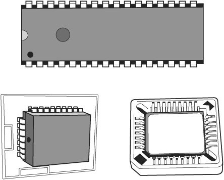
If you fail to heed this warning or something interrupts the update procedure, you will be left with a system that has a corrupted BIOS. This means you will not be able to restart the system and redo the procedure, at least not easily. Depending on the motherboard, you might have to replace the flash ROM chip with one that was preprogrammed by the motherboard manufacturer or from a vendor such as BIOSMAN (www.biosman.com), which provides replacement BIOS chips containing the same BIOS code as that provided by your motherboard vendor. This is an unfortunate necessity because your board will be nonfunctional until a valid ROM is present. In some of the latest systems, the flash ROM is soldered into the motherboard so it can't be replaced, rendering the reprogramming idea moot. Figure 4.43 illustrates typical socketed and soldered ROM chips on server motherboards. Figure 4.43. Socketed and soldered ROM BIOS chips. However, this doesn't mean that the only way out is a complete motherboard replacement. Most motherboards with soldered-in flash ROMs have a special BIOS recovery procedure that can be performed. This hinges on a special non-erasable part of the flash ROM that is reserved for this purpose. In the unlikely event that a flash upgrade is interrupted catastrophically, the BIOS might be left in an unusable state. You should check the documentation for your system to determine whether the system's BIOS supports flash recovery and how to perform a BIOS recovery. Some servers use a two-chip BIOS to enable BIOS recovery. Changes are made to the secondary BIOS chip, leaving the BIOS code in the primary section alone so it can be used as a backup in case of failure. This feature is sometimes known as the rolling BIOS. With either BIOS recovery or rolling BIOS technology, it may be necessary to adjust a chip on the motherboard to enable or configure recovery options. See your server or motherboard documentation for details. Troubleshooting BIOS and System ProblemsWhen an x86-based system is first powered on, the system runs a POST. If errors are encountered during the POST, you usually see a text error message displayed onscreen. Errors that occur very early in the POST might happen before the video card is initialized. These types of errors can't be displayed, so the system uses two other alternatives for communicating the error message. One is beepingthe system beeps the speaker in a specific pattern that indicates which error has occurred. The other alternative is to send a hexadecimal error code to I/O port address 80h, which can be read by a special card in one of the bus slots. When the ROM BIOS is performing the POST, in most systems the results of these tests are continuously sent to I/O Port 80h so they can be monitored by special diagnostics cards called POST cards (see Figure 4.44). These tests sometimes are called manufacturing tests because they were designed for testing systems on the assembly line without video displays attached. Figure 4.44. A typical POST card with two-digit hexadecimal code display (left) and a POST card in operation (right). A POST card has a two-digit hexadecimal display used to report the number of the currently executing test routine. Before executing each test, a hexadecimal numeric code is sent to the port and then the test is run. If the test fails and locks up the machine, the hexadecimal code of the last test being executed remains on the card's display. POST cards are available from vendors such as JDR (www.jdr.com), Ultra-X (www.uxd.com), eSupport (www.esupport.com), and many others. A PCI POST card will work in any system with PCI or PCI-X slots. Some ISA POST cards are still available, but you should purchase them only if you are maintaining legacy servers with ISA or EISA slots. Many tests are executed in a system before the video display card is enabled, especially if the display is EGA or VGA. Therefore, many errors can occur that would lock up the system before the system could possibly display an error code through the video system. Because not all these errors generate beep codes, to most normal troubleshooting procedures, a system with this type of problem (such as a memory failure in Bank 0) would appear completely "dead." By using one of the commercially available POST cards, however, you can often diagnose the problem. These codes are completely BIOS dependent because the card does nothing but display the codes sent to it. Some BIOSs have more detailed POST procedures and therefore send more informative codes. You can purchase POST cards from JDR Microdevices or other sources; they are available in both ISA and PCI bus versions. For simple but otherwise fatal errors that can't be displayed onscreen, most of the BIOS versions also send audio codes that can be used to help diagnose such problems. The audio codes are similar to POST codes, but they are read by listening to the speaker beep rather than by using a special card. The following sections detail the text error codes for all the popular BIOS versions and their beep codes. Error MessagesDuring the boot process on an x86 or Itanium processor, the bootstrap loader routine in the motherboard ROM BIOS reads the first physical sector of each of the bootable drives or devices, which is cylinder 0, head 0, sector 1 in CHS mode or logical block address 0 in LBA mode. The code from the first sector is loaded into RAM, and the last 2 bytes are checked to see whether they match a signature value of 55AAh. If the signature bytes match, that tells the ROM that the first sector contains a valid MBR and that the ROM can continue by transferring control to the MBR code. If the last 2 bytes of the first physical sector do not match 55AAh, the ROM continues by checking the first physical sector of the next bootable device in the boot sequence until it either finds one with a valid MBR or runs out of devices to check. If after checking all the drives or devices in the boot sequence, none are found to have the proper signature bytes indicating a valid MBR, the ROM invokes an interrupt 18h that calls a subroutine that displays an error message. The specific text or wording of the message varies according to the ROM manufacturer and version. The messages are detailed in the following section. ROM BIOS Messages Indicating Boot Failure (No Valid MBR Found)If a hard disk is not properly defined in the system BIOS, you might see an error message similar to one of the following when you start the server:
These and similar error messages indicate that the system could not locate the startup (boot) files on the default boot device. However, such a message could also mean that you left a nonbootable floppy disk in drive A: if the floppy disk is listed before the hard disk in the boot sequence for your server. Before rerunning the BIOS setup to verify that you have properly configured your hard disks, remove any floppy disk found in drive A: and restart your computer. Note For a more complete list of startup error messages, see the documentation for your server or server motherboard. Or see the following documents:
If the system was not trying to boot from a floppy drive, these error messages could indicate that the hard disk is not properly defined in the system BIOS. For example, if the hard disk is configured as user defined but incorrect values for cylinders, heads, or other settings such as LBA (required for ATA/IDE and SATA drives over 8.4GB) are not properly listed, the BIOS will not check the correct part of the hard disk for boot files and will not be able to start the operating system. Or, if the hard disk is listed as "not present" or its host adapter (particularly in the case of a SATA, an ATA RAID, or a SCSI host adapter) has been disabled in the system BIOS, the system will not be able to locate the hard disk and will not be able to start the system. If you determine that the startup hard disk and its host adapter have been properly configured in the system BIOS or by the SCSI BIOS, the hard disk may not have been prepared by the operating system. Or, if the system previously booted from the hard disk, it might indicate that the hard disk's MBR has been corrupted. You can repair a corrupt MBR by using the following programs:
Review the documentation for your operating system for details and cautions. Audio and Video CodesDifferent system BIOS chips use different types of audio (beep) and video (text) error codes to indicate serious system problems. The following sections list these error codes for the most common BIOSs. AMI BIOS POST Error Codes
If you have a POST card, you can find the AMI BIOS POST checkpoint codes in the documentation for your POST card or by downloading this file from the AMI website, at www.ami.com/support/doc/AMIBIOS-codes.pdf. Award BIOS and Phoenix FirstBIOS POST Error CodesCurrently, only one standard beep code exists in the Award BIOS (also known as the Phoenix FirstBIOS). A single long beep followed by two short beeps indicates that a video error has occurred and that the BIOS cannot initialize the video screen to display any additional information. If multiple or continuous beeps occur with an Award BIOS, this usually indicates problems with the power supply or memory.
If you have a POST card, you can find the Award BIOS and Phoenix FirstBIOS POST checkpoint codes at www.uxd.com/award.html (versions 4.x5.x PnP) and www.uxd.com/award2.html (version 6.x).
Phoenix BIOS POST Error CodesPhoenix FirstBIOS Pro is based on Phoenix BIOS 6.x. It uses different beep codes than earlier versions.
If you are using a POST card, you can find the Phoenix BIOS v4 POST codes at www.uxd.com/phoenix.html. IBM BIOS POST Error Codes
| |||||||||||||||||||||||||||||||||||||||||||||||||||||||||||||||||||||||||||||||||||||||||||||||||||||||||||||||||||||||||||||||||||||||||||||||||||||||||||||||||||||||||||||||||||||||||||||||||||||||||||||||||||||||||||||||||||||||||||||||||||||||||||||||||||||||||||||||||||||||||||||||||||||||||||||||||||||||||||||||||||||||||||||||||||||||||||||||||||||||||||||||||||||||||||||||||||||||||||||||||||||||||||||||||||||||||||||||||||||||||||||||||||||||||||||||||||||||||||||||||||||||||||||||||||||||||||||||||||||||||||||||||||||||||||||||||||||||||||||||||||||||||||||||||||||||||||||||||||||||||||||||||||||||||||||||||||||||||||||||||||||||||||||||||||||||||||||||||||||||||||||||||||||||||||||||||||||||||||||||||||||||||||||||||||||||||||||||||||||||||||||||||||||||||||||||||||||||||||||||||||||||||||||||||||||||||||||||||||||||||||||||||||||||||||||||||||||||||||||||||||||||||||||||||||||||||||||||||||||||||||||||||||||||||||||||||||||||||||||||||||||||||||||||||||||||||||||||||||||||
EAN: 2147483647
Pages: 240