Serial ATA
| With the introduction of ATA-7, it seems that the Parallel ATA standard that has been in use for more than 10 years is running out of steam. Sending data at rates faster than 133MBps down a parallel ribbon cable is fraught with all kinds of problems because of signal timing, electromagnetic interference (EMI), and other integrity problems. The solution is in a new ATA interface called Serial ATA (SATA), which is an evolutionary backward-compatible replacement for the Parallel ATA physical storage interface. Serial ATA is backward compatible in that it is compatible with existing software, which will run on the new architecture without any changes. In other words, the existing BIOS, operating systems, and utilities that work on Parallel ATA will also work on Serial ATA. This means Serial ATA supports all existing ATA and ATAPI devices, including CD-ROM and CD-RW drives, DVD drives, tape devices, SuperDisk drives, and any other storage device currently supported by Parallel ATA. Of course, they do differ physically; that is, you won't be able to plug Parallel ATA drives into Serial ATA host adapters, and vice versa. The physical changes are all for the better because Serial ATA uses much thinner cables with only seven pins that are easier to route inside the PC and easier to plug in with smaller redesigned cable connectors. The interface chip designs also are improved with fewer pins and lower voltages. These improvements are all designed to eliminate the design problems inherent in Parallel ATA. Serial ATA won't be integrated into systems overnight; however, it is clear to me that it will eventually replace Parallel ATA as the de facto standard internal storage device interface found in both desktop and portable systems. The transition from ATA to SATA is a gradual one, and during this transition Parallel ATA capabilities will continue to be available. I would also expect that with more than a 10-year history, Parallel ATA devices will continue to be available even after most PCs have gone to SATA. Development for Serial ATA started when the Serial ATA Working Group effort was announced at the Intel Developer Forum in February 2000. The initial members of the Serial ATA Working Group included APT Technologies, Dell, IBM, Intel, Maxtor, Quantum, and Seagate. The first Serial ATA 1.0 draft specification was released in November 2000 and officially published as a final specification in August 2001. The Serial ATA II extensions to this specification, which make Serial ATA suitable for network storage, were released in October 2002. Both can be downloaded from the Serial ATA Working Group website at www.serialata.org. Since forming, the group has added more than 100 Contributor and Adopter companies to the membership from all areas of industry. Systems using Serial ATA were first released in late 2002. The performance of SATA is impressive, although current hard drive designs can't fully take advantage of its bandwidth. Three proposed variations of the standard all use the same cables and connectors; they differ only in transfer rate performance. Initially, only the first version will be available, but the roadmap to doubling and quadrupling performance from there has been clearly established. Table 9.25 shows the specifications for the current and future proposed SATA versions; the next-generation 300MBps version was just introduced in 2005, whereas the 600MBps version is not expected until 2007.
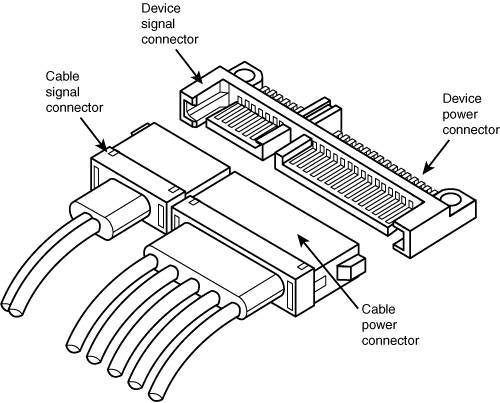
From the table, you can see that Serial ATA sends data only a single bit at a time. The cable used has only seven wires and is a very thin design, with keyed connectors only 14mm (0.55 inches) wide on each end. This eliminates problems with airflow around the wider, Parallel ATA ribbon cables. Each cable has connectors only at each end and connects the device directly to the host adapter (normally on the motherboard). There are no master/slave settings because each cable supports only a single device. The cable ends are interchangeable: The connector on the motherboard is the same as on the device, and both cable ends are identical. Maximum SATA cable length is 1 meter (39.37 inches), which is considerably longer than the 18-inch maximum for Parallel ATA. Even with this thinner, longer, and less expensive cable, transfer rates initially of 150MBps (nearly 13% greater than Parallel ATA/133), and 300MBps (25% greater than Parallel ATA/133), and even 600MBps, are possible. Serial ATA uses a special encoding scheme called 8B/10B to encode and decode data sent along the cable. The 8B/10B transmission code originally was developed (and patented) by IBM in the early 1980s for use in high-speed data communications. This encoding scheme is now used by many high-speed data-transmission standards, including Gigabit Ethernet, Fibre Channel, FireWire, and others. The main purpose of the 8B/10B encoding scheme is to guarantee that there are never more than four 0s (or 1s) transmitted consecutively. This is a form of run length limited (RLL) encoding (called RLL 0,4) in which the 0 represents the minimum and the 4 represents the maximum number of consecutive 0s in each encoded character. The 8B/10B encoding also ensures that there are never more than six or fewer than four 0s (or 1s) in a single encoded 10-bit character. Because 1s and 0s are sent as voltage changes on a wire, this ensures that the spacing between the voltage transitions sent by the transmitter will be fairly balanced, with a more regular and steady stream of pulses. This presents a more steady load on the circuits, increasing reliability. The conversion from 8-bit data to 10-bit encoded characters for transmission leaves a number of 10-bit patterns unused. Several of these additional patterns are used to provide flow control, delimit packets of data, perform error checking, or perform other special needs. The physical transmission scheme for SATA uses what is called differential NRZ (Non Return to Zero). This uses a balanced pair of wires, each carrying plus or minus 0.25V (one-quarter volt). The signals are sent differentially: If one wire in the pair is carrying +0.25V, the other wire is carrying0.25V, where the differential voltage between the two wires is always 0.5V (a half volt). This means that for a given voltage waveform, the opposite voltage waveform is sent along the adjacent wire. Differential transmission minimizes electromagnetic radiation and makes the signals easier to read on the receiving end. A 15-pin power cable and power connector are optional with SATA, providing 3.3V power in addition to the 5V and 12V provided via the industry-standard 4-pin device power connectors. Although it has 15 pins, this new power connector design is only 24mm (0.945 inches). With three pins designated for each of the 3.3V, 5V, and 12V power levels, enough capacity exists for up to 4.5 amps of current at each voltage, which is ample for even the most power-hungry drives. For compatibility with existing power supplies, SATA drives can be made with either the original, standard 4-pin device power connector or the new 15-pin SATA power connector, or both. If the drive doesn't have the type of connector you needed, adapters are available to convert from one type to the other. Figure 9.19 shows what the new SATA signal and power connectors look like. The pinouts for the Serial ATA data and optional power connectors are shown in Tables 9.26 and 9.27. Figure 9.19. SATA (Serial ATA) signal and power connectors.
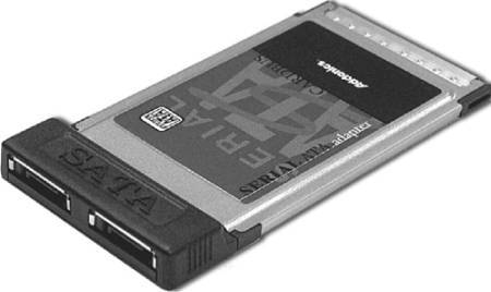
The configuration of Serial ATA devices is also much simpler because the master/slave or cable select jumper settings used with Parallel ATA are no longer necessary. Serial ATA is ideal for laptop and notebook systems, and it will eventually replace Parallel ATA in those systems as well. In late 2002, Fujitsu demonstrated a prototype 2.5-inch SATA drive. Most 2.5-inch hard drive manufacturers were waiting for mobile chipsets supporting SATA to be delivered before officially introducing mobile SATA drives. Both the chipsets and the drives began arriving in 2005, and by late 2005 the first laptops were available with SATA drives. Even if your laptop system does not support SATA internally, you can add an SATA interface externally via a PC Card, such as the Addonics CardBus Serial ATA adapter. This card adds two high-speed Serial ATA ports to any laptop or notebook computer via a PC Card slot. This enables you to connect drives with 2.5 times the data transfer rate of USB 2.0. The card plus an external cable sells for under $100. Figure 9.20 shows the Addonics CardBus Serial ATA adapter. Figure 9.20. Addonics CardBus Serial ATA adapter. Although SATA is not normally designed to be used as an external interface, Addonics has available external drive enclosures as well as a special cable that pulls power from a spare USB port. Using a special cable that's provided, you can connect external hard drives or even CD-ROM/DVD drives via a high-speed SATA connection. Figure 9.21 shows the special Addonics cable, which allows a variety of external SATA devices to be connected to any portable system. Figure 9.21. Addonics Serial ATA devices for Laptops.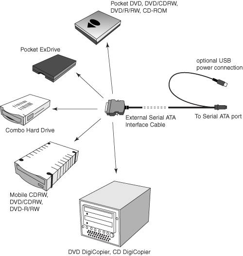 Like Parallel ATA, Serial ATA was designed to be the primary storage interface used inside a PC and was not designed to be used as an external interface. As such, SATA is not designed to compete with high-speed external device interfaces, such as SCSI, USB 2.0, or IEEE 1394 (FireWire). | |||||||||||||||||||||||||||||||||||||||||||||||||||||||||||||||||||||||||||||||||||||||||||||||||||||||||||||||
EAN: 2147483647
Pages: 180
- Chapter I e-Search: A Conceptual Framework of Online Consumer Behavior
- Chapter III Two Models of Online Patronage: Why Do Consumers Shop on the Internet?
- Chapter IV How Consumers Think About Interactive Aspects of Web Advertising
- Chapter IX Extrinsic Plus Intrinsic Human Factors Influencing the Web Usage
- Chapter XI User Satisfaction with Web Portals: An Empirical Study