IO Processing
| < Day Day Up > |
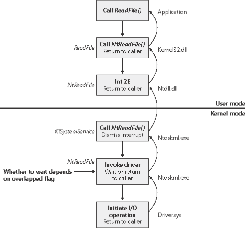
I/O ProcessingNow that we've covered the structure and types of drivers and the data structures that support them, let's look at how I/O requests flow through the system. I/O requests pass through several predictable stages of processing. The stages vary depending on whether the request is destined for a device operated by a single-layered driver or for a device reached through a multilayered driver. Processing varies further depending on whether the caller specified synchronous or asynchronous I/O, so we'll begin our discussion of I/O types with these two then move on to others. Types of I/OApplications have several options for the I/O requests they issue. For example, they can specify synchronous or asynchronous I/O, I/O that maps a device's data into the application's address space for access via application virtual memory rather than I/O APIs, and I/O that transfers data between a device and noncontiguous application buffers in a single request. Furthermore, the I/O manager gives the drivers the choice of implementing a shortcut I/O interface that can often mitigate IRP allocation for I/O processing. In this section, we'll explain each of these I/O variations. Synchronous I/O and Asynchronous I/OMost I/O operations that applications issue are synchronous; that is, the application waits while the device performs the data transfer and returns a status code when the I/O is complete. The program can then continue and access the transferred data immediately. When used in their simplest form, the Windows ReadFile and WriteFile functions are executed synchronously. They complete an I/O operation before returning control to the caller. Asynchronous I/O allows an application to issue an I/O request and then continue executing while the device transfers the data. This type of I/O can improve an application's throughput because it allows the application thread to continue with other work while an I/O operation is in progress. To use asynchronous I/O, you must specify the FILE_FLAG_OVERLAPPED flag when you call the Windows CreateFile function. Of course, after issuing an asynchronous I/O operation, the thread must be careful not to access any data from the I/O operation until the device driver has finished the data transfer. The thread must synchronize its execution with the completion of the I/O request by monitoring a handle of a synchronization object (whether that's an event object, an I/O completion port, or the file object itself) that will be signaled when the I/O is complete. Regardless of the type of I/O request, internally, I/O operations issued to a driver on behalf of the application are performed asynchronously; that is, once an I/O request has been initiated, the device driver returns to the I/O system. Whether or not the I/O system returns immediately to the caller depends on whether the file was opened for synchronous or asynchronous I/O. Figure 9-8 illustrates the flow of control when a read operation is initiated. Notice that if a wait is done, which depends on the overlapped flag in the file object, it is done in kernel mode by the NtReadFile function. Figure 9-8. Control flow for an I/O operation
You can test the status of a pending asynchronous I/O with the Windows HasOverlappedIo- Completed function. If you're using I/O completion ports (described in the "I/O Completion Ports" section later in this chapter), you can use the GetQueuedCompletionStatus function. Fast I/OFast I/O is a special mechanism that allows the I/O system to bypass generating an IRP and instead go directly to the file system driver or cache manager to complete an I/O request. (Fast I/O is described in detail in chapters 11 and 12.) A driver registers its fast I/O entry points by entering them in a structure pointed to by the PFAST_IO_DISPATCH pointer in its driver object.
Mapped File I/O and File CachingMapped file I/O is an important feature of the I/O system, one that the I/O system and the memory manager produce jointly. (See Chapter 7 for details on how mapped files are implemented.) Mapped file I/O refers to the ability to view a file residing on disk as part of a process's virtual memory. A program can access the file as a large array without buffering data or performing disk I/O. The program accesses memory, and the memory manager uses its paging mechanism to load the correct page from the disk file. If the application writes to its virtual address space, the memory manager writes the changes back to the file as part of normal paging. Mapped file I/O is available in user mode through the Windows CreateFileMapping and Map- ViewOfFile functions. Within the operating system, mapped file I/O is used for important operations such as file caching and image activation (loading and running executable programs). The other major consumer of mapped file I/O is the cache manager. File systems use the cache manager to map file data in virtual memory to provide better response time for I/O- bound programs. As the caller uses the file, the memory manager brings accessed pages into memory. Whereas most caching systems allocate a fixed number of bytes for caching files in memory, the Windows cache grows or shrinks depending on how much memory is available. This size variability is possible because the cache manager relies on the memory manager to automatically expand (or shrink) the size of the cache, using the normal working set mechanisms explained in Chapter 7. By taking advantage of the memory manager's paging system, the cache manager avoids duplicating the work that the memory manager already performs. (The workings of the cache manager are explained in detail in Chapter 11.) Scatter/Gather I/OWindows also supports a special kind of high-performance I/O that is called scatter/gather, available via the Windows ReadFileScatter and WriteFileGather functions. These functions allow an application to issue a single read or write from more than one buffer in virtual memory to a contiguous area of a file on disk instead of issuing a separate I/O request for each buffer. To use scatter/gather I/O, the file must be opened for noncached I/O, the user buffers being used have to be page-aligned, and the I/Os must be asynchronous (overlapped). Furthermore, if the I/O is directed at a mass storage device, the I/O must be aligned on a device sector boundary and have a length that is a multiple of the sector size. I/O Request PacketsThe I/O request packet (IRP) is where the I/O system stores information it needs to process an I/O request. When a thread calls an I/O service, the I/O manager constructs an IRP to represent the operation as it progresses through the I/O system. If possible, the I/O manager allocates IRPs from one of two per-processor IRP nonpaged look-aside lists: the small-IRP lookaside list stores IRPs with one stack location (IRP stack locations are described shortly), and the large-IRP look-aside list contains IRPs with multiple stack locations. By default, the system stores IRPs with eight stack locations on the large-IRP look-aside list, but once per minute the system adjusts the number of stack locations allocated based on how many stack locations have been required. If an IRP requires more stack locations than are contained in the IRPs on the large-IRP look-aside list, the I/O manager allocates IRPs from nonpaged pool. After allocating and initializing an IRP, the I/O manager stores a pointer to the caller's file object in the IRP. Note
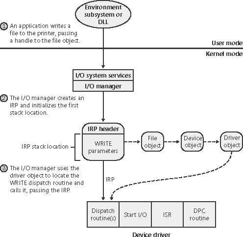
Figure 9-9 shows a sample I/O request that demonstrates the relationship between an IRP and the file, device, and driver objects described in the preceding sections. Although this example shows an I/O request to a single-layered device driver, most I/O operations aren't this direct; they involve one or more layered drivers. (This case will be shown later in this section.) Figure 9-9. Data structures involved in a single-layered driver I/O request
IRP Stack LocationsAn IRP consists of two parts: a fixed header (often referred to as the IRP's body) and one or more stack locations. The fixed portion contains information such as the type and size of the request, whether the request is synchronous or asynchronous, a pointer to a buffer for buffered I/O, and state information that changes as the request progresses. An IRP stack location contains a function code (consisting of a major code and a minor code), function-specific parameters, and a pointer to the caller's file object. The major function code identifies which of a driver's dispatch routines the I/O manager invokes when passing an IRP to a driver. An optional minor function code sometimes serves as a modifier of the major function code. Power and Plug and Play commands always have minor function codes. Most drivers specify dispatch routines to handle only a subset of possible major function codes, including create (open), read, write, device I/O control, power, Plug and Play, System (for WMI commands), and close. (See the following experiment for a complete listing of major function codes.) File system drivers are an example of a driver type that often fills in most or all of its dispatch entry points with functions. The I/O manager sets any dispatch entry points that a driver doesn't fill to point to its own IopInvalidDeviceRequest, which returns an error code to the caller indicating that the function specified for the device is invalid.
While active, each IRP is usually stored in an IRP list associated with the thread that requested the I/O. This arrangement allows the I/O system to find and cancel any outstanding IRPs if a thread terminates or is terminated with outstanding I/O requests.
IRP Buffer ManagementWhen an application or a device driver indirectly creates an IRP by using the NtReadFile, NtWriteFile, or NtDeviceIoControlFile system services (or the Windows API functions corresponding to these services, which are ReadFile, WriteFile, and DeviceIoControl), the I/O manager determines whether it needs to participate in the management of the caller's input or output buffers. The I/O manager performs three types of buffer management:
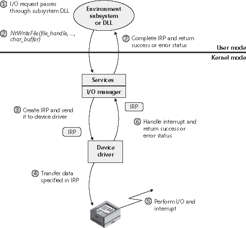
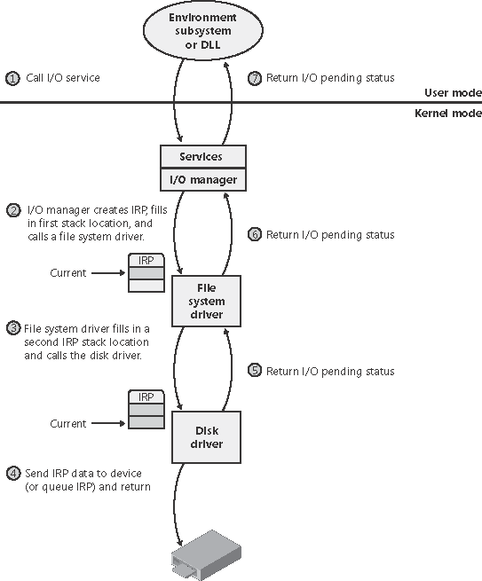
For each type of buffer management, the I/O manager places applicable references in the IRP to the locations of the input and output buffers. The type of buffer management the I/O manager performs depends on the type of buffer management a driver requests for each type of operation. A driver registers the type of buffer management it desires for read and write operations in the device object that represents the device. Device I/O control operations (those performed by NtDeviceIoControlFile) are specified with driver-defined I/O control codes, and a control code includes a description of the buffer management the I/O manager should use when issuing IRPs that contain that code. Drivers commonly use buffered I/O when callers transfer requests smaller than one page (4 KB on x86 processors) and use direct I/O for larger requests. A page is approximately the buffer size at which the trade-off between the copy operation of buffered I/O matches the overhead of the memory lock performed by direct I/O. File system drivers commonly use neither I/O because no buffer management overhead is incurred when data can be copied from the file system cache into the caller's original buffer. The reason that most drivers don't use either I/O is that a pointer to a caller's buffer is valid only while a thread of the caller's process is executing. If a driver must transfer data from or to a device in an ISR or a DPC routine, it must ensure that the caller's data is accessible from any process context, which means that the buffer must have a system virtual address. Drivers that use neither I/O to access buffers that might be located in user-space must take special care to ensure that buffer addresses are both valid and do not reference kernel-mode memory. Failure to do so could result in crashes or in security vulnerabilities, where applications have access to kernel-mode memory or can inject code into the kernel. The ProbeForRead and ProbeForWrite functions that the kernel makes available to drivers verify that a buffer resides entirely in the user-mode portion of the address space. To avoid a crash from referencing an invalid user-mode address, drivers can access user-mode buffers from within exception- handling code (called try/except blocks) that catch any invalid memory faults and translate them into error codes to return to the application. I/O Request to a Single-Layered DriverThis section traces a synchronous I/O request to a single-layered kernel-mode device driver. Handling a synchronous I/O to a single-layered driver consists of seven steps:
These seven steps are illustrated in Figure 9-10. Figure 9-10. Queuing and completing a synchronous request
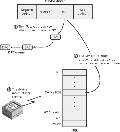
Now that we've seen how an I/O is initiated, let's take a closer look at interrupt processing and I/O completion. Servicing an InterruptAfter an I/O device completes a data transfer, it interrupts for service and the Windows kernel, I/O manager, and device driver are called into action. Figure 9-11 illustrates the first phase of the process. (Chapter 3 describes the interrupt dispatching mechanism, including DPCs. We've included a brief recap here because DPCs are key to I/O processing.) Figure 9-11. Servicing a device interrupt (phase 1)
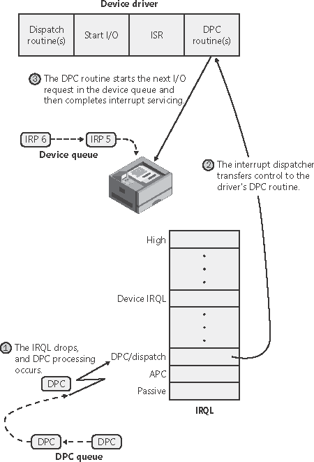
When a device interrupt occurs, the processor transfers control to the kernel trap handler, which indexes into its interrupt dispatch table to locate the ISR for the device. ISRs in Windows typically handle device interrupts in two steps. When an ISR is first invoked, it usually remains at device IRQL only long enough to capture the device status and then stop the device's interrupt. It then queues a DPC and exits, dismissing the interrupt. Later, when the DPC routine is called, the device finishes processing the interrupt. When that's done, the device calls the I/O manager to complete the I/O and dispose of the IRP. It might also start the next I/O request that is waiting in the device queue. The advantage of using a DPC to perform most of the device servicing is that any blocked interrupt whose priority lies between the device IRQL and the DPC/dispatch IRQL is allowed to occur before the lower-priority DPC processing occurs. Intermediate-level interrupts are thus serviced more promptly than they otherwise would be. This second phase of an I/O (the DPC processing) is illustrated in Figure 9-12. Figure 9-12. Servicing a device interrupt (phase 2)
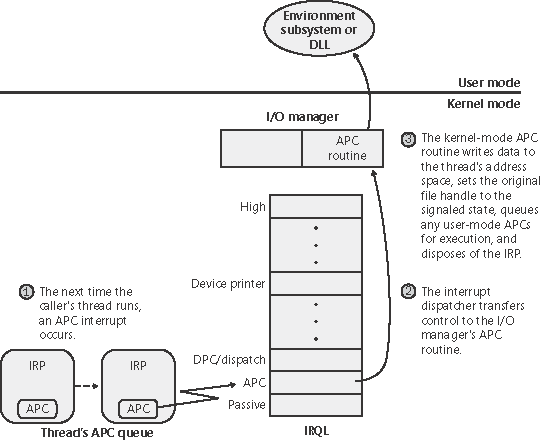
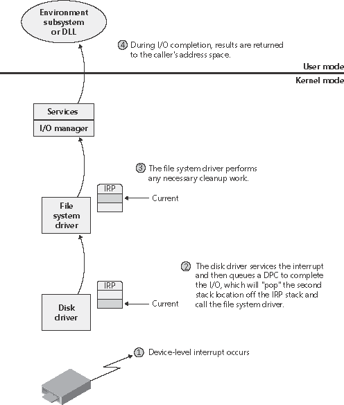
Completing an I/O RequestAfter a device driver's DPC routine has executed, some work still remains before the I/O request can be considered finished. This third stage of I/O processing is called I/O completion and is initiated when a driver calls IoCompleteRequest to inform the I/O manager that it has completed processing the request specified in the IRP (and the stack location that it owns). The steps I/O completion entails vary with different I/O operations. For example, all the I/O services record the outcome of the operation in an I/O status block, a data structure the caller supplies. Similarly, some services that perform buffered I/O require the I/O system to return data to the calling thread. In both cases, the I/O system must copy some data that is stored in system memory into the caller's virtual address space. If the IRP completed synchronously, the caller's address space is current and directly accessible, but if the IRP completed asynchronously, the I/O manager must delay IRP completion until it can access the caller's address space. To gain access to the caller's virtual address space, the I/O manager must transfer the data "in the context of the caller's thread" that is, while the caller's thread is executing (which means that caller's process is the current process and has its address space active on the processor). It does so by queuing a kernel-mode asynchronous procedure call (APC) to the thread. This process is illustrated in Figure 9-13. Figure 9-13. Completing an I/O request (phase 1)
As explained in Chapter 3, APCs execute in the context of a particular thread, whereas a DPC executes in arbitrary thread context, meaning that the DPC routine can't touch the user-mode process address space. Remember too that DPCs have a higher software interrupt priority than APCs. The next time that thread begins to execute at low IRQL, the pending APC is delivered. The kernel transfers control to the I/O manager's APC routine, which copies the data (if any) and the return status into the original caller's address space, frees the IRP representing the I/O operation, and sets the caller's file handle (and any caller-supplied event or I/O completion port) to the signaled state. The I/O is now considered complete. The original caller or any other threads that are waiting on the file (or other object) handle are released from their waiting state and readied for execution. Figure 9-14 illustrates the second stage of I/O completion. Figure 9-14. Completing an I/O request (phase 2)
A final note about I/O completion: the asynchronous I/O functions ReadFileEx and WriteFileEx allow a caller to supply a user-mode APC as a parameter. If the caller does so, the I/O manager queues this APC to the caller's thread APC queue as the last step of I/O completion. This feature allows a caller to specify a subroutine to be called when an I/O request is completed or canceled. User-mode APC completion routines execute in the context of the requesting thread and are delivered only when the thread enters an alertable wait state (such as calling the Windows SleepEx, WaitForSingleObjectEx, or WaitForMultipleObjectsEx function). SynchronizationDrivers must synchronize their access to global driver data and hardware registers for two reasons:
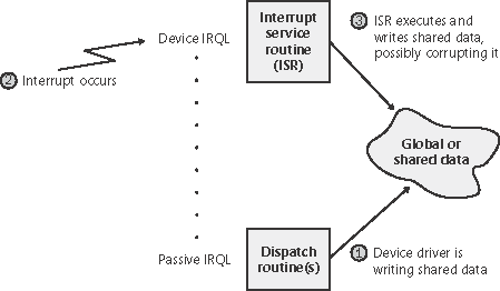
Without synchronization, corruption could occur for example, because device driver code running at a passive IRQL when a caller initiates an I/O operation can be interrupted by a device interrupt, causing the device driver's ISR to execute while its own device driver is already running. If the device driver was modifying data that its ISR also modifies, such as device registers, heap storage, or static data, the data can become corrupted when the ISR executes. Figure 9-15 illustrates this problem. Figure 9-15. Queuing an asynchronous request to layered drivers
To avoid this situation, a device driver written for Windows must synchronize its access to any data that the device driver shares with its ISR. Before attempting to update shared data, the device driver must lock out all other threads (or CPUs, in the case of a multiprocessor system) to prevent them from updating the same data structure. The Windows kernel provides a special synchronization routine called KeSynchronizeExecution that device drivers call when they access data that their ISRs also access. This kernel-synchronization routine keeps the ISR from executing while the shared data is being accessed. On a single CPU system, this routine raises the IRQL to the level associated with the ISR before updating a structure. On a multiprocessor system, however, because a driver can execute on two or more processors at once, this technique isn't enough to block other accessors. Therefore, another mechanism, a spinlock, is used to lock a structure for exclusive access from a particular CPU. (Spinlocks are explained in the section "Synchronization" in Chapter 3.) A driver can also use KeAcquireInterruptSpinLock to access an interrupt object's spin lock directly, although it's generally faster to rely on KeSynchronizeExecution for synchronization with an ISR. By now, you should realize that although ISRs require special attention, any data that a device driver uses is subject to being accessed by the same device driver running on another processor. Therefore, it's critical for device driver code to synchronize its use of any global or shared data (or any accesses to the physical device itself). If the ISR uses that data, the device driver must use KeSynchronizeExecution; otherwise, the device driver can use standard kernel spinlocks. I/O Requests to Layered DriversThe preceding section showed how an I/O request to a simple device controlled by a single device driver is handled. I/O processing for file-based devices or for requests to other layered drivers happens in much the same way. The major difference is, obviously, that one or more additional layers of processing are added to the model. Figure 9-16 shows how an asynchronous I/O request travels through layered drivers. It uses as an example a disk controlled by a file system. Figure 9-16. Queuing an asynchronous request to layered drivers
Once again, the I/O manager receives the request and creates an I/O request packet to represent it. This time, however, it delivers the packet to a file system driver. The file system driver exercises great control over the I/O operation at that point. Depending on the type of request the caller made, the file system can send the same IRP to the disk driver or it can generate additional IRPs and send them separately to the disk driver.
The file system is most likely to reuse an IRP if the request it receives translates into a single straightforward request to a device. For example, if an application issues a read request for the first 512 bytes in a file stored on a floppy disk, the FAT file system would simply call the disk driver, asking it to read one sector from the floppy disk, beginning at the file's starting location. To accommodate its reuse by multiple drivers in a request to layered drivers, an IRP contains a series of IRP stack locations (not to be confused with the stack used by threads to store function parameters and return addresses). These data areas, one for every driver that will be called, contain the information that each driver needs to execute its part of the request for example, function code, parameters, and driver context information. As Figure 9-16 illustrates, additional stack locations are filled in as the IRP passes from one driver to the next. You can think of an IRP as being similar to a stack in the way data is added to it and removed from it during its lifetime. However, an IRP isn't associated with any particular process, and its allocated size doesn't grow and shrink. The I/O manager allocates an IRP from one if its IRP lookaside lists or nonpaged system memory at the beginning of the I/O operation.
After the disk driver finishes a data transfer, the disk interrupts and the I/O completes, as shown in Figure 9-17. Figure 9-17. Completing a layered I/O request
As an alternative to reusing a single IRP, a file system can establish a group of associated IRPs that work in parallel on a single I/O request. For example, if the data to be read from a file is dispersed across the disk, the file system driver might create several IRPs, each of which reads some portion of the request from a different sector. This queuing is illustrated in Figure 9-18. Figure 9-18. Queuing associated IRPs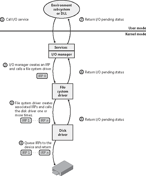 The file system driver delivers the associated IRPs to the device driver, which queues them to the device. They are processed one at a time, and the file system driver keeps track of the returned data. When all the associated IRPs complete, the I/O system completes the original IRP and returns to the caller, as shown in Figure 9-19. Figure 9-19. Completing associated IRPs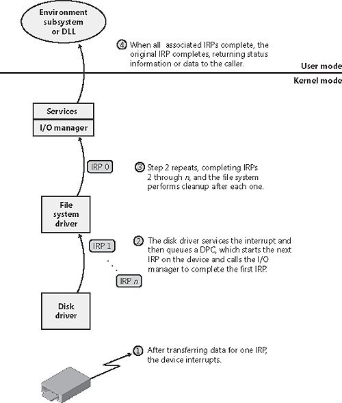 Note
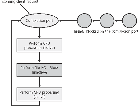
I/O Completion PortsWriting a high-performance server application requires implementing an efficient threading model. Having either too few or too many server threads to process client requests can lead to performance problems. For example, if a server creates a single thread to handle all requests, clients can become starved because the server will be tied up processing one request at a time. A single thread could simultaneously process multiple requests, switching from one to another as I/O operations are started, but this architecture introduces significant complexity and can't take advantage of multiprocessor systems. At the other extreme, a server could create a big pool of threads so that virtually every client request is processed by a dedicated thread. This scenario usually leads to thread-thrashing, in which lots of threads wake up, perform some CPU processing, block while waiting for I/O, and then, after request processing is completed, block again waiting for a new request. If nothing else, having too many threads results in excessive context switching, caused by the scheduler having to divide processor time among multiple active threads. The goal of a server is to incur as few context switches as possible by having its threads avoid unnecessary blocking, while at the same time maximizing parallelism by using multiple threads. The ideal is for there to be a thread actively servicing a client request on every processor and for those threads not to block when they complete a request if additional requests are waiting. For this optimal process to work correctly, however, the application must have a way to activate another thread when a thread processing a client request blocks on I/O (such as when it reads from a file as part of the processing). The IoCompletion ObjectApplications use the IoCompletion executive object, which is exported to Windows as a completion port, as the focal point for the completion of I/O associated with multiple file handles. Once a file is associated with a completion port, any asynchronous I/O operations that complete on the file result in a completion packet being queued to the completion port. A thread can wait for any outstanding I/Os to complete on multiple files simply by waiting for a completion packet to be queued to the completion port. The Windows API provides similar functionality with the WaitForMultipleObjects API function, but the advantage that completion ports have is that concurrency, or the number of threads that an application has actively servicing client requests, is controlled with the aid of the system. When an application creates a completion port, it specifies a concurrency value. This value indicates the maximum number of threads associated with the port that should be running at any given time. As stated earlier, the ideal is to have one thread active at any given time for every processor in the system. Windows uses the concurrency value associated with a port to control how many threads an application has active. If the number of active threads associated with a port equals the concurrency value, a thread that is waiting on the completion port won't be allowed to run. Instead, it is expected that one of the active threads will finish processing its current request and check to see whether another packet is waiting at the port. If one is, the thread simply grabs the packet and goes off to process it. When this happens, there is no context switch, and the CPUs are utilized nearly to their full capacity. Using Completion PortsFigure 9-20 shows a high-level illustration of completion port operation. A completion port is created with a call to the Windows API function CreateIoCompletionPort. Threads that block on a completion port become associated with the port and are awakened in last in, first out (LIFO) order so that the thread that blocked most recently is the one that is given the next packet. Threads that block for long periods of time can have their stacks swapped out to disk, so if there are more threads associated with a port than there is work to process, the in-memory footprints of threads blocked the longest are minimized. Figure 9-20. I/O completion port operation
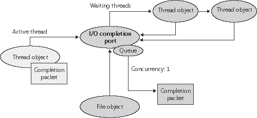
A server application will usually receive client requests via network endpoints that are represented as file handles. Examples include Windows Sockets 2 (Winsock2) sockets or named pipes. As the server creates its communications endpoints, it associates them with a completion port and its threads wait for incoming requests by calling GetQueuedCompletionStatus on the port. When a thread is given a packet from the completion port, it will go off and start processing the request, becoming an active thread. A thread will block many times during its processing, such as when it needs to read or write data to a file on disk or when it synchronizes with other threads. Windows detects this activity and recognizes that the completion port has one less active thread. Therefore, when a thread becomes inactive because it blocks, a thread waiting on the completion port will be awakened if there is a packet in the queue. Microsoft's guidelines are to set the concurrency value roughly equal to the number of processors in a system. Keep in mind that it's possible for the number of active threads for a completion port to exceed the concurrency limit. Consider a case in which the limit is specified as 1. A client request comes in, and a thread is dispatched to process the request, becoming active. A second request arrives, but a second thread waiting on the port isn't allowed to proceed because the concurrency limit has been reached. Then the first thread blocks waiting for a file I/O, so it becomes inactive. The second thread is then released, and while it's still active, the first thread's file I/O is completed, making it active again. At that point and until one of the threads blocks the concurrency value is 2, which is higher than the limit of 1. Most of the time, the active count will remain at or just above the concurrency limit. The completion port API also makes it possible for a server application to queue privately defined completion packets to a completion port by using the PostQueuedCompletionStatus function. A server typically uses this function to inform its threads of external events, such as the need to shut down gracefully. I/O Completion Port OperationWindows applications create completion ports by calling the Windows API CreateIoCompletionPort and specifying a NULL completion port handle. This results in the execution of the NtCreateIoCompletion system service. The executive's IoCompletion object is based on the kernel synchronization object called a queue. Thus, the system service creates a completion port object and initializes a queue object in the port's allocated memory. (A pointer to the port also points to the queue object because the queue is at the start of the port memory.) A queue object has a concurrency value that is specified when a thread initializes one, and in this case the value that is used is the one that was passed to CreateIoCompletionPort. KeInitializeQueue is the function that NtCreateIoCompletion calls to initialize a port's queue object. When an application calls CreateIoCompletionPort to associate a file handle with a port, the NtSetInformationFile system service is executed with the file handle as the primary parameter. The information class that is set is FileCompletionInformation, and the completion port's handle and the CompletionKey parameter from CreateIoCompletionPort are the data values. NtSet- InformationFile dereferences the file handle to obtain the file object and allocates a completion context data structure. Finally, NtSetInformationFile sets the CompletionContext field in the file object to point at the context structure. When an asynchronous I/O operation completes on a file object, the I/O manager checks to see whether the CompletionContext field in the file object is non-NULL. If it is, the I/O manager allocates a completion packet and queues it to the completion port by calling KeInsertQueue with the port as the queue on which to insert the packet. (Remember that the completion port object and queue object are synonymous.) When a server thread invokes GetQueuedCompletionStatus, the system service NtRemoveIo- Completion is executed. After validating parameters and translating the completion port handle to a pointer to the port, NtRemoveIoCompletion calls KeRemoveQueue. As you can see, KeRemoveQueue and KeInsertQueue are the engines behind completion ports. They are the functions that determine whether a thread waiting for an I/O completion packet should be activated. Internally, a queue object maintains a count of the current number of active threads and the maximum number of active threads. If the current number equals or exceeds the maximum when a thread calls KeRemoveQueue, the thread will be put (in LIFO order) onto a list of threads waiting for a turn to process a completion packet. The list of threads hangs off the queue object. A thread's control block data structure has a pointer in it that references the queue object of a queue that it's associated with; if the pointer is NULL, the thread isn't associated with a queue. Windows keeps track of threads that become inactive because they block on something other than the completion port by relying on the queue pointer in a thread's control block. The scheduler routines that possibly result in a thread blocking (such as KeWaitForSingleObject, KeDelayExecutionThread, and so on) check the thread's queue pointer. If the pointer isn't NULL, the functions call KiActivateWaiterQueue, a queue-related function that decrements the count of active threads associated with the queue. If the resultant number is less than the maximum and at least one completion packet is in the queue, the thread at the front of the queue's thread list is awakened and given the oldest packet. Conversely, whenever a thread that is associated with a queue wakes up after blocking, the scheduler executes the function KiUnwaitThread, which increments the queue's active count. Finally, the PostQueuedCompletionStatus Windows API function results in the execution of the NtSetIoCompletion system service. This function simply inserts the specified packet onto the completion port's queue by using KeInsertQueue. Figure 9-21 shows an example of a completion port object in operation. Even though two threads are ready to process completion packets, the concurrency value of 1 allows only one thread associated with the completion port to be active, and so the two threads are blocked on the completion port. Figure 9-21. I/O completion port operation
Driver VerifierThe Driver Verifier, which was introduced in Chapter 7, includes several options that check the correctness of I/O-related operations. Figure 9-22 shows the Windows Server 2003 Driver Verifier Manager with these options selected. Figure 9-22. Driver Verifier I/O-related options Even when you don't select any options, the Verifier monitors drivers selected for verification, looking for a number of illegal operations including calling kernel-memory pool functions at invalid IRQL, double-freeing memory, and requesting a zero-sized memory allocation. Additional checks enabled by checking I/O-related options include:
The Driver Verifier serves primarily as a tool to help device driver developers discover bugs in their code, but it can also be a powerful tool for systems administrators experiencing crashes. Chapter 14 describes its role in crash analysis troubleshooting. |

| < Day Day Up > |
EAN: 2147483647
Pages: 158