Chapter 11 - IP Telephony
| Chapter 11 IP Telephony | ||
| This chapter provides an overview of IP telephony and the protocols developed for signaling within IP telephony networks. Because many of the standards are still under development, I have chosen not to provide the details of these protocols. They continue to change on a regular basis. As the standards evolve, those that are specific to SS7 will be documented in later editions. | ||||
| What started as a fad has suddenly redefined traditional networks around the world. Although experts agree that TCP/IP networks are not favorable for telephony applications because of latency issues, companies are eagerly finding ways to circumvent the issues and take advantage of the Internet as a means for transporting voice and data around the world. Although TCP/IP may not be the ideal transport for real-time applications, it is certainly more efficient and much more economical than conventional networks used today. | ||||
| One of the drivers is the cost of TCP/IP-based switches. Although they currently do not provide the capacities of traditional circuit-switching platforms, they are much cheaper, allowing small startups to deploy networks much quicker for a fraction of the cost. This has caused existing carriers to review their network plans and implement new deployments of IP-based equipment, in many cases replacing their existing legacy switches. | ||||
| This of course introduces new challenges to the industry. The TCP/IP protocols must be modified to support telephony applications. The Internet Engineering Task Force (IETF), as well as the ITU, is actively modifying these standards today. Although voice transmission over IP networks is of primary concern, much is also to be done in the area of signaling. | ||||
| This book will only focus on the work being done for signaling. The voice and data transmission is really outside the scope of this book and is best served in other publications. We will review the architecture, however, because this is vital to understanding how signaling works in IP-based networks. | ||
| The timeframe for these networks is now. Already companies are deploying systems and transmitting voice traffic through the public Internet, as well as specially engineered IP networks (the preferred approach). Many of the RBOCs have taken advantage of some of these IP carriers, although they would never admit that their traffic is being sent through the public Internet. In the next few years, we will continue to see widespread deployment of IP-based telephony networks with both old and new carriers. This is especially true of the wireless carriers, who are eager to explore the possibilities of IP-based services. | ||||
| What Is IP Telephony? | ||||
| IP telephony encompasses the use of IP-based networks for the purpose of transporting both data and voice. They depend on server-based systems as switches (sometimes referred to as ''softswitches"). The general concept is to eliminate the intelligence found in many legacy switches today in the edge of the network and rely on more centralized servers to provide call control to the edge devices. | ||||
| The subscriber is served by an IP-based device, which replaces the end office switch used in conventional networks. The purpose of this device is to provide connections (via IP, ATM, or whatever medium is required) to the subscriber. Ideally, this medium is IP. The voice is packetized using Customer Provided Equipment (CPE). All of the switching intelligence is provided by a controller, which sits in a more regional location. The controller supports all of the devices within its defined zone. | ||||
| The controller provides call control functions, instructing the devices on how to handle a specific call. Controllers use a signaling protocol to communicate with these devices, as well as a signaling protocol to communicate with one another. All of these protocols are based on IP as the transport. | ||||
| In order for these devices to communicate with devices in another network, there must be some device that provides a bridge. This requires yet another level of signaling. If calls are to be sent to the PSTN, SS7 is the only accepted form of signaling. A signaling gateway provides the bridge between IP networks and the PSTN. | ||||
| What is different in these networks from conventional telephony networks is the ability to connect to an IP "cloud," rather than dedicated circuits between each of the entities. This is of course the primary advantage of using packet switching technology rather than circuit-switched. While signaling system #7 is a packet-switched protocol, some adaptations are necessary to work in this environment. SS7 uses many timers at levels 2 and 3 to maintain the integrity of each "link," network element and to guarantee delivery of all messages. We will discuss this more later in this chapter. | ||||
| By eliminating the direct connections between all entities, and by utilizing IP as the transport, carriers can now realize substantial savings in their network infrastructures. The devices used in these networks are substantially cheaper than circuit-switched equipment, and carriers can eliminate other expensive equipment such as multiplexers and TDM-based transmission equipment. | ||||
| Still, there is a need to connect to traditional telephony networks. This will be the case for many years to come because there is a huge investment in networks of this type, and IP telephony networks are still far too immature in design to replace TDM networks. As previously mentioned, in order to connect into the TDM networks, signaling system #7 (SS7) is required. | ||||
| It is important to understand that SS7 is not necessarily being replaced by new IP signaling protocols. Rather, SS7 is being modified to meet the requirements of IP networks. When one looks at the ISUP and TCAP protocols, it becomes obvious that the services brought by these two protocols are not easily duplicated by any other protocols. They have been developed over many years to support telephony services. TCP/IP does not have any comparable protocols to support these functions. Creating new IP-based protocols to replace ISUP and TCAP would be far too complex and time-consuming. It makes far more sense to modify SS7 to support IP networks than to create new replacement protocols. | ||||
| This is not to say that SS7 may not someday be replaced entirely. The telephony network as we know it today is undergoing dramatic changes. These changes may render SS7 obsolete some years from now. In the meantime, work continues on modifying SS7 network to interoperate with IP telephony networks. | ||||
| Support of SS7 transport over IP facilities is being addressed through both the ITU and the IETF. In the meantime, vendors are deploying proprietary solutions to get their products to market. | ||||
| Perhaps the only vendor who has had any level of success with this is Tekelec. This company has developed a protocol interface called Transport Adaption Layer Interface (TALI) that is designed to transport SS7 over pure IP networks. To date, more than 140 vendors have downloaded this software (www.tekelec.com) and registered with Tekelec to implement this interface on their solutions. | ||||
| Although I may be a little biased as an employee of Tekelec, I believe the TALI interface deserves discussion here because of its already wide-spread industry support. Although many vendors have tried solutions of their own, TALI is the only protocol in use today in live networks transporting SS7 over IP facilities. | ||
| Although TALI is receiving widespread acceptance, it is not meant to replace the work of the IETF. In order for vendors to interoperate with one another, they must be compliant with whatever industry standard is adopted. TALI is viewed as an enabler to allow vendors and carriers to begin their deployment of SS7 over IP today, rather than wait on the standard committees to complete their work. | ||||
| The Signaling Challenge in IP | ||||
| The challenge in SS7 is replacing or emulating the procedures found in MTP in an IP network. TCP/IP does not provide the same functions as MTP; specifically, link management, traffic management, and route management. These functions must be emulated in the IP world to allow SS7 to work. They are vital to maintaining the quality of service we have become accustomed to here in the US. | ||||
| Standards are now focusing on emulating the services of SS7 levels 2 and 3 so these three functions can be provided seamlessly regardless if signaling messages come from the PSTN or IP networks. | ||||
| To understand the roles of the standards being developed, let's first look at the architecture of IP telephony networks and the elements providing call functions. | ||||
| IP Telephony Network Architectures | ||||
| IP telephony networks are not as complicated as they may seem. If you look at the basic functions of a legacy switching system, you will find three basic functions: call control, the switching matrix, and the physical transmission interface. The idea in IP telephony is to break these different functions out and distribute them through the network using inexpensive servers. | ||||
| In Figure 11.1, the physical transmission interface resides at the edge of the network. The switching matrix is really a series of routers and hubs, providing input and output ports. Depending on the address of the call (determined by the call control function), the packetized voice is routed through these devices to the destination point. | ||||
| The call control function is deployed in zones. Each call controller (sometimes referred to as call agent) manages the devices within its own zone. This is depicted in Figure 11.1. | ||||
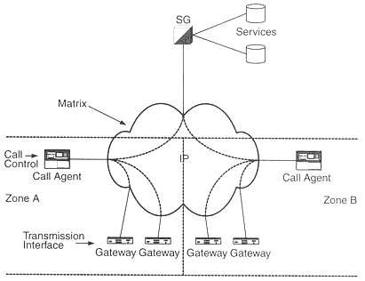 | ||
| Figure 11.1 The basic functions of a circuit switching system can be found in an IP telephony network, the difference being the functions have been distributed around the network using low cost computer equipment rather than expensive switching equipment. | ||||
| The SS7 interface is more centralized in most networks. There are a couple of different thoughts about how SS7 is deployed in these networks. Some vendors use software stacks enabling SS7 in their solutions (such as controllers). Many have found out that these software stacks (implemented on PCs and servers) are not dependable and often result in failures. When these elements fail, calls do not pass through the network. | ||||
| For this reason, many vendors have begun to migrate away from software stacks and partner with vendors to provide more telco-hardened platforms for SS7. Signal Transfer Points (STPs) that support the function of signaling gateways can now be found. These are also being used as front ends to controllers and other entities in the IP network. | ||||
| Figure 11.2 depicts an ideal network architecture. By centralizing the signaling gateway (or deploying in regions), carriers can control their most precious network resources more closely. As depicted in Figure 11.2, the intelligence of the network is provided by the signaling gateway, which acts as an interface to these resources. | ||||
.gif) | |||
| Figure 11.2 A more ideal IP telephony network architecture is illustrated here using ITU architecture. The same approach can be taken with IETF architecture. By centralizing the network intelligence, the carrier has much more control and flexibility over their network. | ||||
| Another concept still in its infancy is billing through SS7, rather than creating billing records at the edge of the network. In legacy networks, this practice is already gaining popularity. SS7 provides a much more efficient method for collecting call data used for billing purposes and eliminates the need for generating this data in switching equipment, collecting the data from these switches, and processing the data at some central billing center. | ||||
| The same advantages exist in IP telephony networks. By centralizing this process using SS7, the edge devices responsible for actually generating phone calls and routing them through the network do not need software to generate call detail records. | ||||
| Monitoring of the entire network is critical, and several approaches can be used. One is to deploy "probes" throughout the network that then report back to a central monitoring system. Another is to actually connect to the signaling gateway and monitor the signaling messages as they pass through the signaling gateway. | ||||
| Regardless of the architecture used, there is one critical factor to consider when designing signaling over IP networks. Latency is a critical issue in IP networks and the round trip time for messages to traverse the network must be closely engineered. An SS7 message should experience no more than 100ms round trip time to prevent expiration of level 2 and level 3 timers. | ||
| Standardization | ||||
| The biggest issue with IP telephony in the year 2000 is lack of standardization. Both the ITU and the IETF are working diligently to develop the necessary standards to ensure interoperability between vendors systems, as well as address the many QoS issues brought about by latency factors in TCP/IP networks. There is no clear indication when these standards will be completed, but suffice it to say that it won't happen quickly. | ||||
| In the meantime, vendors are finding ways to deploy solutions using existing technologies as a work-around to the lack of standards. Q.9231 (also known as broadband ISDN), ATM, Frame Relay, and other older technologies are being used to take the place of non-existent standards. ATM has been the biggest success story because carriers can use this as the network backbone and ATM provides QoS as part of the protocol. | ||||
| Signaling, however, is another issue. Although there are some preliminary standards being adopted and deployed in IP networks, there still is not a standard for SS7 transport through an IP network. The signaling protocols currently being used allow carriers to communicate within their own networks, but when connections to the PSTN must be made, they are left with no solution. | ||||
| There are basically two functions that have been defined for signaling protocol work, adaptation, and transport. Adaptation functions act like APIs interfacing between telephony and IP protocols. This is where Tekelec's TALI plays a major role, as well as the protocols currently under development in the ITU and IETF. | ||||
| The purpose of the adaptation protocols is to emulate the services provided by the MTP, maintaining link management, traffic management, and route management. | ||||
| The transport function provides a reliable transfer of signaling traffic across the network. The IETF is currently defining a new protocol that will be a peer to IP called Simple Control Transmission Protocol (SCTP). | ||||
| To better understand the role the standards being developed play in IP telephony, we need to look at the architecture of IP telephony networks and the elements defined in these networks. | ||
| ITU H.323 | ||||
| The ITU is expanding on their H.323 Recommendations, which originally were to cover facsimile and video conferencing, but have since been expanded to include IP telephony. | ||||
| The purpose of H.323 is to allow users to run multimedia applications such as voice and video, using existing LAN infrastructures, without concern for latency factors. | ||||
| The original specification for H.323 was for visual telephone systems as well as LAN equipment that provided a non-guaranteed QoS. Version 1 of this standard was accepted in October of 1996. | ||||
| Version 2 was modified to accommodate packet-based multimedia communications, specifically Voice over IP (VoIP) and Voice over ATM (VoATM). Security was added in this version. Version 2 was accepted in January of 1998. Version 3 is now under development. | ||||
| Figure 11.3 shows the functions defined in H.323 for IP telephony networks. This is where some confusion sets in because the ITU uses different terminology than the IETF. I have adopted the IETF terminology for simplicity, but also defined the ITU terminology here for clarity. It should also be noted that there is no one-for-one mapping between the functions defined by the ITU and those defined by the IETF. | ||||
| The function at the customer premise is referred to as a terminal. This could be a computer, telephone, or any other device capable of supporting voice, data, and possibly video. As seen in Figure 11.4, terminals use H.245 to negotiate channel usage and capabilities (call control). The terminals communicate with gatekeepers for call control. | ||||
| Call signaling (call setup and teardown) is provided by H.225. This is communicated from terminal to terminal (through the gatekeeper). | ||||
| Gatekeepers are the central points for call control. They are deployed in "zones," controlling all terminals and gateways within their zone. Gatekeepers provide call control signaling, call authorization (based on the Q.921 specification), bandwidth management, and call management. | ||||
| Figure 11.5 shows the functions provided by the gatekeeper. Many of the functions shown in Figure 11.5 can be moved to a more central point, such as a signaling gateway, or they can be distributed throughout the network at the gatekeepers (as depicted in Figure 11.5). | ||||
.gif) | ||
| Figure 11.3 The ITU has defined a different set of functions than the IETF. The entities shown in this illustration are functions defined by the ITU. The connections shown between each function are not meant to be interpreted as point-to-point physical connections, but as logical connections. | ||||
| |||||||||||||||||||||||||||||||||||||||||||||||||||||||
| Figure 11.4 H.323 Terminal-side protocol stack. The shaded areas represent terminal resident standards. | ||||
.gif) | ||
| Figure 11.5 H.323 Gatekeeper protocol stack. The shaded areas represented gatekeeper resident standards. | ||||
| Call signaling is accomplished using Q.921 signaling between endpoints. These signaling messages can be sent directly to the endpoint (provided they are within the same zone/network) or sent to the gatekeeper. The gatekeeper can either process the signaling message, or simply pass it on to the appropriate endpoint. | ||||
| Terminals register with their gatekeeper using Registration Admission/Status (RAS). This protocol allows the gatekeeper to maintain a status of all terminals within its zone. The gatekeeper also provides address resolution from LAN aliases to IP addresses. Three functions are provided by RAS. Registration is the announcing by an endpoint of its presence and providing its LAN address. Admission controls LAN access based on call authorization, available bandwidth (and the bandwidth required for the call), and other criteria. | ||||
| The gatekeeper can also provide call routing. The advantage of allowing the gatekeeper to provide this function is once again centralization of intelligence within each zone. This also makes billing simpler within each zone. | ||||
| Call management uses a state machine to maintain status of all active calls within the gatekeepers' zone. | ||||
| In the case of bandwidth management, the gatekeeper can reject call connections based on bandwidth availability. This provides additional flexibility to network administrators who can set thresholds in the gatekeepers, preventing multimedia applications from "hogging" all the bandwidth in networks shared by data applications. Call management maintains status of all calls in progress through a state machine. | ||||
| The gateway is an optional function in ITU networks. They are used when connecting to another network. Gateways provide protocol conversion, as well as establish links between the PSTN and ISDN networks. | ||
| Protocol conversion may be necessary when connecting to unlike networks. For example, in the case of international networks, each country may be using its own version of SS7, as well as call signaling. In addition, the voice is encoded differently than here in the U.S. The gateway provides conversion of the signaling as well as the voice. | ||||
| Figure 11.7 shows the protocol stack by application, as defined in H.323. | ||||
.gif) | ||||
| Figure 11.6 H.323 Gateway protocol stack. The shaded areas represent gateway resident standards. | ||||
.gif) | ||||
| Figure 11.7 The ITU protocol stack for data, voice, audio, and video applications. | ||||
| IETF Sigtran | ||
| This working group within the IETF has been commissioned with defining a set of protocols to be used for signaling within IP telephony networks. Each of these protocols has distinct functions, performed in different segments of the network. Figure 11.8 illustrates a typical IP telephony network (high-level view) and where these protocols are being used. | ||||
| Media Gateway (MG) | ||||
| The media gateway (MG) shown in Figure 11.8 supports packetized voice and the interface to whatever medium the voice is to be transported on. The media gateway performs the task of packetizing voice and providing connections from switched circuits (TDM) to packetized circuits (IP, frame relay, or ATM). The MG does not necessarily reside at a subscriber premise, but interfaces to equipment located at the subscriber premise. | ||||
| The MG is responsible for media conversion, resource allocation and resource management, and event notifications. It is responsible for reporting events to the media gateway controller (MGC) within its zone. | ||||
.gif) | ||||
| Figure 11.8 A high level view of what a IETF network might look like, and what protocol standards would be used in this network. | ||||
| Media Conversion | ||||
| The MG must be able to provide conversion from TDM circuit switched connections to ATM, IP, or frame relay connections. This includes the packetization of the voice itself. Media processing includes transcoding, conferencing, interactive voice recognition, and other audio resource functions. | ||||
| Resource Allocation | ||||
| Resource allocation includes the reservation and release of all resources. It is important to understand that although the MG is responsible for resource allocation and management, it does so under the direction of the media gateway controller. The MGC holds the ultimate responsibility of defining what resources are to be allocated for any one call. | ||||
| The MG is capable of providing either point-to-point connections or point-to-multipoint connections (such as in a conference call). The MG must also support voice, data, video, and facsimile. | ||||
| Event Notification | ||||
| The MG must also maintain the state of all resources and report the state to the media gateway controller. If a particular resource fails, the MG reports the failure to the MGC. The MGC maintains a state table for all resources within the MGs in its zone. | ||||
| Media Gateway Controller (MGC) | ||||
| The media gateway is responsible for controlling all of the media gateways within its zone. As previously mentioned in the description of the media gateway, the media gateway controller performs a number of call control functions that are typically found in the call control portion of a legacy switch. | ||||
| This includes determining and controlling signals used on specific circuits, such as ringing and busy tone. The MGC also determines the QoS required for any one connection at the MG. | ||||
| In short, the call handling is performed at the MGC, rather than at the MG itself. This allows carriers to deploy less expensive equipment at the edge of their networks. | ||
| Signaling Gateway (SG) | ||||
| The IETF defines the signaling gateway as being the bridge to the PSTN. But is also supports the function of the SG at the MG level. When the SG function is part of the MG, the role is somewhat diluted from that of a signaling gateway providing STP functions to the network. | ||||
| Keep in mind that global title translation and gateway screening are best accomplished at a different level than the MG. These STP functions should be more centralized, as depicted in Figure 11.8. | ||||
| The signaling gateway should also be capable of providing conversion between SS7 addresses (point codes) to IP addresses. One method of address resolution utilizes the point code of an incoming message from the PSTN, as well as the CIC to determine the appropriate IP address of the receiving MG. If a message is TCAP, the address resolution is provided using the point code and subsystem number. | ||||
| Using IP in signaling networks rather than TDM point-to-point connections has a number of advantages. One of the most significant advantages is more efficient (and less expensive) use of bandwidth. With TDM circuits, a lot of ancillary equipment is required to maintain the circuit. With IP networks, the equipment is much less expensive. | ||||
| The addressing in IP signaling networks provides far more flexibility than in conventional SS7 networks. All entities in the SS7 environment are addressed through the use of point codes. The point code administrator in each country (in the U.S., SAIC) issues point codes. In some countries, point codes are difficult to come by (due to rationing by the ITU). | ||||
| When a carrier uses an IP network, the entities in the IP network are addressed by IP addresses rather than point codes. This requires the use of a signaling gateway to resolve the addresses from the SS7 network to the addresses in the IP network. The routing is based usually on a destination point code, and in the case of ISUP messages, the CIC range. | ||||
| This means that media gateways and media gateway controllers can be added into the network and assigned IP addresses. The routing in the signaling gateway changed to provide routes to the new entities. The connection to other networks is through the signaling gateway, so any network additions do not necessarily have to be advertised to other networks. The carrier can maintain transparency to outside networks. | ||||
| This is accomplished by assigning ranges of unique CIC codes to the gateways within the network. The signaling gateway uses one point code assignment for all of the gateways and uses the unique CIC ranges to route the messages to the appropriate gateways. | ||||
| If a carrier wishes to maintain even more flexibility in their network routing, a point code can be assigned (again within the signaling gateway) to regions, with unique CIC combinations within each region (allowing for CIC duplication in different regions). | ||||
| When TALI is used, automatic CIC registration is supported. This allows carriers to deploy additional gateways without the need to change the routing tables in the signaling gateway. The gateways advertise (register) their CIC ranges to the signaling gateway automatically. | ||||
| The same scheme is used when routing TCAP messages. The routing is based on a point code and subsystem number. If a carrier is deploying a number of services, each service is assigned a unique subsystem number. The outside networks need only to know the one point code and subsystem number (or the point code alone when GTT is provided). | ||||
| When a database requires additional servers to increase capacity, an additional point code is not required (as is the case in conventional SS7 networks). The new server can be added using IP addressing, and the routing assignments can be made in the signaling gateway to ensure load sharing and subsystem management. | ||||
| One of the biggest advantages to launching services in IP networks is the flexibility provided to the carrier. Rather than depend on expensive legacy SCP solutions, carriers can develop their own applications deployed on carrier grade servers. Already many carriers have begun developing creative new services themselves, rather than depend on vendors to provide ''canned" applications. | ||||
| This factor alone will greatly enhance the concept of IP networking and provide great benefits to new carriers looking to differentiate themselves from the competition. Of course, as is the case with traditional signaling networks, the signaling network should be deployed first, providing an infrastructure that will allow the carrier to expand into new markets quickly and launch exciting new services to address the needs of their customers. Figure 11.9 depicts an example (the addresses are purely for example) of how IP provides additional flexibility in routing for signaling networks and valuable resources. | ||||
.gif) | ||
| Figure 11.9 SS7 point codes are used within the signaling gateway for routing purposes, but the true routing keys are the CIC for ISUP and the subsystem number for TCAP. A wide variety of combinations can be mixed and matched though, using OPC, DPC, CIC, and SSN combinations. | ||||
| Three protocols are under development by the IETF for SS7 transport in IP signaling networks. These are described later in this chapter. The purpose of these protocols is to provide transport of ISUP and TCAP messages across IP networks, without the use of the MTP protocols. | ||||
| MTP is not eliminated entirely in IP networks. Parts of MTP are still required for routing purposes and for the destination entities to properly process the message. In these cases, the MTP portions are "tunneled" in IP or encapsulated into a TCP header for transmission to the destination. | ||||
| Before we discuss these three new protocols, we must first look at the other signaling protocols within the IP telephony network and understand how they are used. | ||||
| IP Telephony Signaling | ||||
| Figure 11.10 shows the typical IP telephony network and the protocols used for signaling (or proposed for signaling) between the various entities. The ITU architecture or the IETF architecture has basically three entities: a gateway, a call agent responsible for call control, and a signaling gateway. The ITU network actually adds a third device for providing gateway functions between networks. | ||||
| The signaling for these architectures varies depending on whether you are looking at IETF or ITU. This chapter focuses on IETF solutions, although ITU standards are shown here as well (in overview form). | ||||
| Signaling between the various entities is not necessarily SS7. Several protocols are being developed for this function. Figure 11.10 shows the IETF protocols proposed for IP telephony networks and where they are used within the network. | ||||
.gif) | ||||
| Figure 11.10 The signaling protocols proposed for IP telephony networks, and where they are used in the network. | ||||
| Between gateways and gateway controllers (call agents) are two competing protocols: media gateway controller protocol (MGCP) and Megaco. The Megaco protocol began as MGCP and later evolved into an entirely separate protocol under the working group Megaco. | ||||
| MGCP also continues to evolve with the endorsement of the International Softswitch Consortium and the MSF. Either one may eventually become the finalized IETF standard after development has been completed. In the interim, vendors continue to implement both protocols in their solutions, selecting one over the other depending on their own opinions. The ITU has endorsed the Megaco protocol and are using it as the base for their H.245 protocol. | ||||
| The purpose of either one of these protocols is to provide communications for the MG back to the MGC, and vice versa, for call control and call signaling. In some cases, even Q.931 can be used as an interim solution (as is the case with many vendor solutions). Keep in mind that these are for the purpose of signaling only. The packetized bearer traffic (voice, data, and so on) uses the IP protocol Real Time Protocol (RTP). | ||||
| The Session Initiation Protocol (SIP) was designed for communications between two MGCs. This is somewhat analogous to SS7 in a conventional telephony network. For SS7 transport within an IP telephony network, three new protocols are under development by the IETF: Simple Control Transmission Protocol (SCTP), MTP2 User Adaptation (M2UA), and MTP3 User Adaptation (M3UA). | ||||
| Simple Control Transmission Protocol (SCTP) | ||||
| A number of limitations within TCP impede the performance of SS7 messaging. The nature of TCP and how messages are prioritized requires unnecessary delays in processing of TCP packets. To ensure that a complete packet is received, the push function of TCP must be used. | ||||
| These limitations were taken into consideration when SCTP was developed. Initially, SCTP was to use the services of UDP for delivery. This was soon changed, however, when it was determined that UDP was not reliable enough a transport and in itself created problems. SCTP was then changed to a peer protocol to TCP and UDP. | ||||
| SCTP is a connection-oriented protocol providing a number of functions. Besides segmentation and reassembly, SCTP also provides path management. When SCTP determines that a particular path to an endpoint is unreachable, SCTP reports to the application (ISUP, TCAP, and so on) the change in the state of the path. | ||||
.gif) | ||
| Figure 11.11 The protocol stack used for SS7 transport in an IP telephony network involves quite a few more protocols than in a conventinal SS7 network, as shown in comparison here. | ||||
| Likewise, if for some reason a number of retransmissions occur for any given session, SCTP considers the destination as unreachable and reports the fault to the application. A counter is used by SCTP to determine the threshold of retransmissions allowed. Periodic heartbeats are sent to all established sessions to ensure their reachability. | ||||
| SCTP is capable of releasing a session gracefully in the event of a fault, reporting the cause of the release to the application using cause codes. This helps in troubleshooting network trouble. | ||||
| Both IPv4 addressing (32 bit) and IPv6 (128 bit) are supported. | ||||
| MTP3 User Adaptation Layer (M3UA) | ||||
| As shown in Figure 11.12, M3UA uses the services of SCTP for delivery and provides services to the application level (ISUP, TCAP, and so on). When compared with conventional SS7, the combination of SCTP and M3UA is equivalent to the services provided by MTP. | ||||
| Although Figure 11.12 shows IP and Ethernet, both SCTP and M3UA are designed to be transport-independent. ATM or frame relay can be used just as easily. The purpose of M3UA is to provide the same services as MTP3, with some exceptions. | ||||
| Conventional SS7 has a boundary limitation of 256 octets (MTP3 limitation). This limitation does not exist with M3UA. However, although M3UA does not have the same boundary limitation, signaling gateways must still follow the 256 octet boundary to prevent fragmentation of messages being delivered to the PSTN. | ||||
| Another role of M3UA is mapping of point codes to IP addresses. As discussed earlier, the routing is based on four parameters; DPC, OPC, SIO, and CIC range (ISUP messages). For TCAP, the routing is based on DPC, OPC, SIO, and SSN. | ||||
.gif) | ||
| Figure 11.12 The full protocol stack for ISUP or TCAP transport using IETF standards. | ||||
| MTP2 User Adaptation Layer (M2UA) | ||||
| M2UA provides the same services as MTP2, including link management. M2UA maintains link states and has the ability to perform changeovers and link management functions related to processor outages. | ||||
| One difference between MTP2 and M2UA is the absence of forward and backward sequence numbers. Instead, SCTP provides transmit sequence numbers (TSNs) in their place. Figure 11.12 shows the protocol stack including M3UA. | ||||
| When M3UA is added, there are several layers of protocol, yet the use of IP is still far more efficient than MTP over TDM circuits. | ||||
Signaling System #7, Fifth Edition (McGraw-Hill Computer Communications Series)
ISBN: 007146879X
EAN: 2147483647
EAN: 2147483647
Year: 2000
Pages: 23
Pages: 23
Authors: Travis Russell