4.10 AES42 Digital Microphone Interface
| | ||
| | ||
| | ||
4.10 AES42 Digital Microphone Interface
This digital microphone interface is based on the AES3 two-channel interface and includes options for powering and synchronization of microphones. Most digital microphones currently in existence employ conventional capsule technology with A/D conversion very close to the microphone capsule rather than direct digital transduction of the acoustic waveform. There are nonetheless some advantages to be had in using digital transmission of audio signals from microphones, principally the potential for higher quality and lower noise as a result of conversion close to the capsule and the avoidance of long cable runs in the analog domain at low signal level. A microphone that conforms to this standard is typically referred to as an AES3-MIC.
The AES42 standard 33 notes that some patent rights may relate to the interface in question and that licensing of some elements may be required.
4.10.1 Principles
The AES42 (AES3-MIC) interface is a standard AES3 interface that also carries power for the microphone. There is also a proposal to adopt a slightly different XLR connector to the normal one, termed the XLD connector, intended to avoid the possibility of damaging equipment not designed for the power supplying capacity of this interface. The XLD connector is identified with a striped 'zebra' ring to distinguish it, but this is not mandatory and there is some disagreement about the need for it (some say that studio practice has managed adequately for years with some XLR connectors carrying phantom power and others not). A combination of coded grooves and keys enables XLD connectors to be used in a variety of combinations with ordinary XLR connectors, or in the fully coded form may prevent one connector from being inserted into a socket of the other type.
If the microphone is monophonic both subframes of the digital interface carry identical information, except in single-channel-double- sampling-frequency modes where they carry successive samples of the one channel.
4.10.2 Powering
The form of phantom powering in this standard is not the same as the 48 volt system used with analog microphones. In this standard the so-called 'digital phantom power' (DPP) is 10 volts applied to both legs of the balanced AES3 cable via a centre tap on the cable side of the transformer. Maximum continuous load is specified as 250 mA, with a peak load of 300 mA when charging additional load capacitance .
4.10.3 Remote Control and Status Reporting
An AES3-MIC may be remote controlled using pulsed modulation of the power supply voltage (see below), with positive-going pulses of 2 0.2 volts that carry data at a rate of 750 bits per second (at 48 kHz sampling frequency or multiples) or proportionally lower for 44.1 kHz and multiples . The remote control information can indicate changes of microphone settings such as directivity pattern (omni, cardioid, etc.), attenuation, limiting, gain, muting and high-pass filtering. There is also the option for manufacturer-specific settings and extended instructions involving changes of more sophisticated features such as dither type, sampling frequency and so forth.
The microphone's status can be reported back to the receiver by means of the user bit channel of the AES3 interface. In this application the user bits are assembled into a 24-byte structure, in the same way as channel status information, synchronized by the same Z preamble that indicates the start of a 192-bit channel status block.
4.10.4 Synchronization
There are two modes of operation of an AES3-MIC. In Mode 1 the microphone is self-clocking and generates its own sampling frequency reference. As a consequence of this all mics in a studio would be unsynchronized and each would have a slightly different sampling frequency. Any mixing console dealing with their digital signals would have to apply sampling frequency conversion. In Mode 2, microphones can be synchronized to a common reference signal and this is achieved by transmitting additional data in the remote control information to the microphone. As shown in Figure 4.24 it is intended that a phase comparator be present in each AES3-MIC receiver (say a mixing console input) that compares the relative phase of the word clock extracted from the incoming microphone signal to a reference signal. A binary value is returned to the microphone in the remote control data that adjusts the frequency of its internal clock accordingly , using a D/A convertor to convert the remote control data into a DC voltage and a voltage-controlled crystal oscillator to generate the word clock.
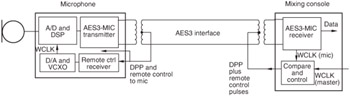
Figure 4.24: Conceptual example of AES42 digital microphone interface.
The resolution of the sync information can be extended from eight to 13 bits for use in high resolution applications where clock accuracy and low jitter are crucial.
| | ||
| | ||
| | ||
EAN: 2147483647
Pages: 120