3.16 The Galois Field
| | ||
| | ||
| | ||
3.16 The Galois Field
Figure 3.26 shows a simple circuit consisting of three D-type latches which are clocked simultaneously . They are connected in series to form a shift register. At (a) a feedback connection has been taken from the output to the input and the result is a ring counter where the bits contained will recirculate endlessly. At (b) one XOR gate is added so that the output is fed back to more than one stage. The result is known as a twisted-ring counter and it has some interesting properties. Whenever the circuit is clocked, the left-hand bit moves to the right-hand latch, the centre bit moves to the left-hand latch and the centre latch becomes the XOR of the two outer latches. The figure shows that whatever the starting condition of the three bits in the latches, the same state will always be reached again after seven clocks, except if zero is used. The states of the latches form an endless ring of non-sequential numbers called a Galois field after the French mathematical prodigy Evariste Galois who discovered them. The states of the circuit form a maximum length sequence because there are as many states as are permitted by the word length. As the states of the sequence have many of the characteristics of random numbers, yet are repeatable, the result can also be called a pseudo-random sequence (prs). As the all-zeros case is disallowed , the length of a maximum length sequence generated by a register of m bits cannot exceed (2 m -1 ) states. The Galois field, however, includes the zero term . It is useful to explore the bizarre mathematics of Galois fields which use modulo-2 arithmetic. Familiarity with such manipulations is helpful when studying the error correction, particularly the Reed-Solomon codes used in recorders . They will also be found in processes which require pseudo-random numbers such as digital dither and randomized channel codes used in, for example, DVB.
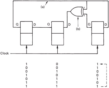
Figure 3.26: The circuit shown is a twisted-ring counter which has an unusual feedback arrangement. Clocking the counter causes it to pass through a series of non-sequential values. See text for details.
The circuit of Figure 3.26 can be considered as a counter and the four points shown will then be representing different powers of 2 from the MSB on the left to the LSB on the right. The feedback connection from the MSB to the other stages means that whenever the MSB becomes 1, two other powers are also forced to one so that the code of 1011 is generated.
Each state of the circuit can be described by combinations of powers of x , such as
x 2 = 100
x = 010
x 2 + x = 110, etc.
This fact that three bits have the same state because they are connected together is represented by the modulo-2 equation:
x 3 + x + 1 = 0
Let x = a , which is a primitive element. Now
| (3.1) | |
In modulo-2
a + a = a 2 + a 2 = 0
a = x = 010
a 2 = x 2 = 100
a 3 = a + 1 = 011 from (3.1)
a 4 = a — a 3 = a ( a + 1) a 2 + a = 110
| a 5 | = a 2 + a + 1 = 111 |
| a 6 | = a — a 5 = a ( a 2 + a + 1) |
| = a 3 + a 2 + a = a + 1 + a 2 + a | |
| = a 2 + 1 = 101 | |
| a 7 | = a ( a 2 + 1) = a 3 + a |
| = a + 1 + a = 1 = 001 |
In this way it can be seen that the complete set of elements of the Galois field can be expressed by successive powers of the primitive element. Note that the twisted-ring circuit of Figure 3.26 simply raises a to higher and higher powers as it is clocked. Thus the seemingly complex multi-bit changes caused by a single clock of the register become simple to calculate using the correct primitive and the appropriate power.
The numbers produced by the twisted-ring counter are not random; they are completely predictable if the equation is known. However, the sequences produced are sufficiently similar to random numbers that in many cases they will be useful. They are thus referred to as pseudo-random sequences. The feedback connection is chosen such that the expression it implements will not factorize. Otherwise a maximum-length sequence could not be generated because the circuit might sequence around one or other of the factors depending on the initial condition. A useful analogy is to compare the operation of a pair of meshed gears. If the gears have a number of teeth which is relatively prime, many revolutions are necessary to make the same pair of teeth touch again. If the number of teeth have a common multiple, far fewer turns are needed.
| | ||
| | ||
| | ||
EAN: 2147483647
Pages: 120