3.15 Cyclic Codes
| | ||
| | ||
| | ||
3.15 Cyclic Codes
In digital audio and video, relatively large quantities of data are involved and it is desirable to use relatively large data blocks to reduce the amount of bandwidth devoted to preambles, addressing and synchronizing. The principle of codewords having a special characteristic will still be employed, but they will be generated and checked algorithmically by equations. The syndrome will then be converted to the bit(s) in error by solving equations.
Where data can be accessed serially , simple circuitry can be used because the same gate will be used for many XOR operations. The circuit of Figure 3.22 is a kind of shift register, but with a particular feedback arrangement which leads it to be known as a twisted-ring counter. If seven message bits AG are applied serially to this circuit, and each one of them is clocked, the outcome can be followed in the diagram. As bit A is presented and the system is clocked, bit A will enter the left-hand latch. When bits B and C are presented, A moves across to the right. Both XOR gates will have A on the upper input from the right-hand latch, the left one has D on the lower input and the right one has B on the lower input. When clocked, the left latch will thus be loaded with the XOR of A and D, and the right one with the XOR of A and B. The remainder of the sequence can be followed, bearing in mind that when the same term appears on both inputs of an XOR gate, it goes out, as the exclusive-OR of something with itself is nothing. At the end of the process, the latches contain three different expressions. Essentially, the circuit makes three parity checks through the message, leaving the result of each in the three stages of the register. In the figure, these expressions have been used to draw up a check matrix. The significance of these steps can now be explained.
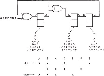
Figure 3.22: When seven successive bits AG are clocked into this circuit, the contents of the three latches are shown for each clock. The final result is a parity-check matrix.
The bits A B C and D are four data bits, and the bits E F and G are redundancy. When the redundancy is calculated, bit E is chosen so that there are an even number of ones in bits A B C and E; bit F is chosen such that the same applies to bits B C D and F, and similarly for bit G. Thus the four data bits and the three check bits form a seven-bit codeword. If there is no error in the codeword, when it is fed into the circuit shown, the result of each of the three parity checks will be zero and every stage of the shift register will be cleared. As the register has eight possible states, and one of them is the error-free condition, then there are seven remaining states, hence the seven-bit codeword. If a bit in the codeword is corrupted, there will be a non-zero result. For example, if bit D fails, the check on bits A B D and G will fail, and a one will appear in the left-hand latch. The check on bits B C D F will also fail, and the centre latch will set. The check on bits A B C E will not fail, because D is not involved in it, making the right-hand bit zero. There will be a syndrome of 110 in the register, and this will be seen from the check matrix to correspond to an error in bit D. Whichever bit fails, there will be a different three-bit syndrome that uniquely identifies the failed bit. As there are only three latches, there can be eight different syndromes. One of these is zero, which is the error-free condition, and so there are seven remaining error syndromes. The length of the codeword cannot exceed seven bits, or there would not be enough syndromes to correct all the bits. This can also be made to tie in with the generation of the check matrix. If 14 bits, A to N, were fed into the circuit shown, the result would be that the check matrix repeated twice, and if a syndrome of 101 were to result, it could not be determined whether bit D or bit K failed. Because the check repeats every seven bits, the code is said to be a cyclic redundancy check (CRC) code.
It has been seen that the circuit shown makes a matrix check on a received word to determine if there has been an error, but the same circuit can also be used to generate the check bits. To visualize how this is done, examine what happens if only the data bits A B C and D are known, and the check bits E F and G are set to zero. If this message, ABCD000, is fed into the circuit, the left-hand latch will afterwards contain the XOR of A B C and zero, which is, of course, what E should be. The centre latch will contain the XOR of B C D and zero, which is what F should be and so on. This process is not quite ideal, however, because it is necessary to wait for three clock periods after entering the data before the check bits are available. Where the data are simultaneously being recorded and fed into the encoder, the delay would prevent the check bits being easily added to the end of the data stream. This problem can be overcome by slightly modifying the encoder circuit as shown in Figure 3.23. By moving the position of the input to the right, the operation of the circuit is advanced so that the check bits are ready after only four clocks. The process can be followed in the diagram for the four data bits A B C and D. On the first clock, bit A enters the left two latches, whereas on the second clock, bit B will appear on the upper input of the left XOR gate, with bit A on the lower input, causing the centre latch to load the XOR of A and B and so on.
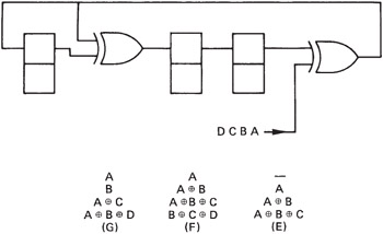
Figure 3.23: By moving the insertion point three places to the right, the calculation of the check bits is completed in only four clock periods and they can follow the data immediately. This is equivalent to premultiplying the data by x 3 .
The way in which the cyclic codes work has been described in engineering terms, but it can be described mathematically if analysis is contemplated.
Just as the position of a decimal digit in a number determines the power of ten (whether that digit means one, ten or 100), the position of a binary digit determines the power of two (whether it means one, two or four). It is possible to rewrite a binary number so that it is expressed as a list of powers of two. For example, the binary number 1101 means 8 + 4 + 1, and can be written:
2 3 + 2 2 + 2
In fact, much of the theory of error correction applies to symbols in number bases other than 2, so that the number can also be written more generally as
x 3 + x 2 + 1 (2 = 1)
and which also looks much more impressive. This expression, containing as it does various powers, is, of course, a polynomial. The circuit of Figure 3.22, which has been seen to construct a parity-check matrix on a codeword, can also be described as calculating the remainder due to dividing the input by a polynomial using modulo-2 arithmetic. In modulo-2 there are no borrows or carries, and addition and subtraction are replaced by the XOR function, which makes hardware implementation very easy. In Figure 3.24 it will be seen that the circuit of Figure 3.22 actually divides the codeword by the polynomial
x 3 + x + 1 or 1011
This can be deduced from the fact that the right-hand bit is fed into two lower-order stages of the register at once. Once all the bits of the message have been clocked in, the circuit contains the remainder. In mathematical terms, the special property of a codeword is that it is a polynomial yielding a remainder of zero when divided by the generating polynomial. The receiver will make this division, and the result should be zero in the error-free case. Thus the codeword itself disappears from the division. If an error has occurred it is considered that this is due to an error polynomial added to the codeword polynomial. If a codeword divided by the check polynomial is zero, a non-zero syndrome must represent the error polynomial divided by the check polynomial. Thus if the syndrome is multiplied by the check polynomial, the latter will be cancelled out and the result will be the error polynomial. If this is added modulo-2 to the received word, it will cancel out the error and leave the corrected data.
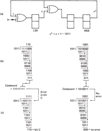
Figure 3.24: Circuit of Figure 3.22 divides by x 3 + x + 1 to find remainder. At (b) this is used to calculate check bits. At (c) right, zero syndrome, no error.
Some examples of modulo-2 division are given in Figure 3.24, which can be compared with the parallel computation of parity checks according to the matrix of Figure 3.22.
The process of generating the codeword from the original data can also be described mathematically. If a codeword has to give zero remainder when divided, it follows that the data can be converted to a codeword by adding the remainder when the data are divided. Generally speaking, the remainder would have to be subtracted, but in modulo-2 there is no distinction. This process is also illustrated in Figure 3.24. The four data bits have three zeros placed on the right-hand end, to make the word length equal to that of a codeword, and this word is then divided by the polynomial to calculate the remainder. The remainder is added to the zeroextended data to form a codeword. The modified circuit of Figure 3.23 can be described as premultiplying the data by x 3 before dividing.
CRC codes are of primary importance for detecting errors, and several have been standardized for use in digital communications. The most common of these are:
x 16 + x 15 + x 2 + 1 (CRC-16)
x 16 + x 12 + x 5 + 1 (CRC-CCITT)
The 16-bit cyclic codes have codewords of length 2 16 -1 or 65 535 bits long. This may be too long for the application. Another problem with very long codes is that with a given raw BER, the longer the code, the more errors will occur in it. There may be enough errors to exceed the power of the code. The solution in both cases is to shorten or puncture the code. Figure 3.25 shows that in a punctured code, only the end of the codeword is used, and the data and redundancy are preceded by a string of zeros. It is not necessary to transmit these zeros, and, of course, errors cannot occur in them. Implementing a punctured code is easy. If a CRC generator starts with the register cleared and is fed with serial zeros, it will not change its state. Thus it is not necessary to provide the zeros, encoding can begin with the first data bit. In the same way, the leading zeros need not be provided during reception . The only precaution needed is that if a syndrome calculates the location of an error, this will be from the beginning of the codeword not from the beginning of the data. Where codes are used for detection only, this is of no consequence.
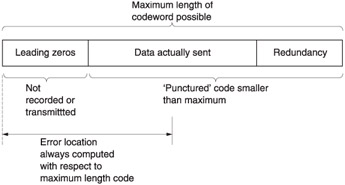
Figure 3.25: Codewords are often shortened , or punctured, which means that only the end of the codeword is actually transmitted. The only precaution to be taken when puncturing codes is that the computed position of an error will be from the beginning of the codeword, not from the beginning of the message.
CRCs are in common use in digital interfaces. The channel status data of the AES/EBU interface, video frames in SD EDH and active lines in HD-SDI are all checked with CRCs.
| | ||
| | ||
| | ||
EAN: 2147483647
Pages: 120