3.17 Introduction to the Reed-Solomon Codes
| | ||
| | ||
| | ||
3.17 Introduction to the Reed-Solomon Codes
The Reed-Solomon codes (Irving Reed and Gustave Solomon) are inherently burst correcting 4 because they work on multi-bit symbols rather than individual bits. The RS codes are also extremely flexible in use. One code may be used both to detect and correct errors. The number of bursts to be corrected can be chosen at the design stage by the amount of redundancy. A further advantage of the RS codes is that they can be used in conjunction with a separate error-detection mechanism in which case they perform the correction only by erasure. RS codes operate at the theoretical limit of correcting efficiency. In other words, no more efficient code can be found.
In the simple CRC system described in section 3.15, the effect of the error is detected by ensuring that the codeword can be divided by a polynomial. The CRC codeword was created by addition of a redundant symbol to the data. In the Reed-Solomon codes, several errors can be isolated if the codeword is divisible by a number of polynomials. Clearly, if the codeword must divide by, say, two polynomials , it must have two redundant symbols. This is the minimum case of an RS code. On receiving an RS-coded message there will be two syndromes following the division. In the error-free case, these will both be zero. If both are not zero, there is an error.
It has been stated that the effect of an error is to add an error polynomial to the message polynomial. The number of terms in the error polynomial is the same as the number of errors in the codeword. The codeword divides to zero and the syndromes are a function of the error only. There are two syndromes and two equations. By solving these simultaneous equations it is possible to obtain two unknowns. One of these is the position of the error, known as the locator, and the other is the error bit pattern, known as the corrector . As the locator is the same size as the code symbol, the length of the codeword is determined by the size of the symbol. A symbol size of eight bits is commonly used because it fits in conveniently with both 16-bit audio samples and byte-oriented computers. An eight-bit syndrome results in a locator of the same word length. Eight bits have 2 8 combinations, but one of these is the error-free condition, and so the locator can specify one of only 255 symbols. As each symbol contains eight bits, the codeword will be 255 — 8 = 2040 bits long.
As further examples, five-bit symbols could be used to form a codeword 31 symbols long, and three-bit symbols would form a codeword seven symbols long. This latter size is small enough to permit some worked examples, and will be used further here. Figure 3.27 shows that in the seven-symbol codeword, five symbols of three bits each, AE, are the data, and P and Q are the two redundant symbols. This simple example will locate and correct a single symbol in error. It does not matter, however, how many bits in the symbol are in error.
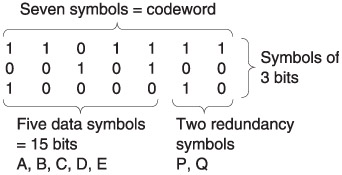
Figure 3.27: A Reed-Solomon codeword. As the symbols are of three bits, there can only be eight possible syndrome values. One of these is all zeros, the error-free case, and so it is only possible to point to seven errors hence the codeword length of seven symbols. Two of these are redundant, leaving five data symbols.
The two check symbols are solutions to the following equations:
A • B • C • D • E • P • Q = 0 ( • =XOR symbol)
a 7 A • a 6 B • a 5 C • a 4 D • a 3 E • a 2 P • a Q = 0
where a is a constant. The original data AE followed by the redundancy P and Q pass through the channel.
The receiver makes two checks on the message to see if it is a codeword. This is done by calculating syndromes using the following expressions, where the (') implies the received symbol which is not necessarily correct:
S = A' • B' • C' • D' • E' P' • Q'
(This is in fact a simple parity check.)
S 1 = a 7 A' • a 6 B' • a 5 C' • a 4 D' • a 3 E' • a 2 P' • a Q'
If two syndromes of all zeros are not obtained, there has been an error. The information carried in the syndromes will be used to correct the error. For the purpose of illustration, let it be considered that D has been corrupted before moving to the general case. D' can be considered to be the result of adding an error of value E to the original value D such that D' = D • E .
As A • B • C • D • E • P • Q = 0
then A • B • C • (D • E ) • E • P • Q = E = S
As D' = D • E
then D = D' • E = D' • S
Thus the value of the corrector is known immediately because it is the same as the parity syndrome S . The corrected data symbol is obtained simply by adding S to the incorrect symbol.
At this stage, however, the corrupted symbol has not yet been identified, but this is equally straightforward:
As a 7 A • a 6 B • a 5 C • a 4 D • a 3 E • a 2 P • a Q = 0
then:
a 7 A • a 6 B • a 5 C • a 4 (D • E ) • a 3 E • a 2 P • a Q = a 4 E = S 1
Thus the syndrome S 1 is the error bit pattern E , but it has been raised to a power of a that is a function of the position of the error symbol in the block. If the position of the error is in symbol k , then k is the locator value and:
S — a k = S 1
Hence:
The value of k can be found by multiplying S by various powers of a until the product is the same as S 1 . Then the power of a necessary is equal to k . The use of the descending powers of a in the codeword calculation is now clear because the error is then multiplied by a different power of a dependent upon its position, known as the locator, because it gives the position of the error. The process of finding the error position by experiment is known as a Chien search.
Whilst the expressions above show that the values of P and Q are such that the two syndrome expressions sum to zero, it is not yet clear how P and Q are calculated from the data. Expressions for P and Q can be found by solving the two RS equations simultaneously . This has been done in Appendix 3.1. The following expressions must be used to calculate P and Q from the data in order to satisfy the codeword equations. These are:
P = a 6 A • a B • a 2 C • a 5 D • a 3 E
Q = a 2 A • a 3 B • a 6 C • a 4 D • a E
In both the calculation of the redundancy shown here and the calculation of the corrector and the locator it is necessary to perform numerous multiplications and raising to powers. This appears to present a formidable calculation problem at both the encoder and the decoder. This would be the case if the calculations involved were conventionally executed. However, the calculations can be simplified by using logarithms. Instead of multiplying two numbers , their logarithms are added. In order to find the cube of a number, its logarithm is added three times. Division is performed by subtraction of the logarithms. Thus all the manipulations necessary can be achieved with addition or subtraction, which is straightforward in logic circuits.
The success of this approach depends upon simple implementation of log tables. Raising a constant, a , known as the primitive element , to successively higher powers in modulo-2 gives rise to a Galois field. Each element of the field represents a different power n of a . It is a fundamental of the RS codes that all the symbols used for data, redundancy and syndromes are considered to be elements of a Galois field. The number of bits in the symbol determines the size of the Galois field, and hence the number of symbols in the codeword.
In Figure 3.28, the binary values of the elements are shown alongside the power of a they represent. In the RS codes, symbols are no longer considered simply as binary numbers, but also as equivalent powers of a . In Reed-Solomon coding and decoding, each symbol will be multiplied by some power of a . Thus if the symbol is also known as a power of a it is only necessary to add the two powers. For example, if it is necessary to multiply the data symbol 100 by a 3 , the calculation proceeds as follows , referring to Figure 3.28:
100 = a 2 so 100 — a 3 = a (2 + 3) = a 5 = 111
Note that the results of a Galois multiplication are quite different from binary multiplication. Because all products must be elements of the field, sums of powers that exceed seven wrap around by having seven subtracted. For example:
a 5 — a 6 = a 11 = a 4 = 110
Figure 3.29 gives an example of the Reed-Solomon encoding process.
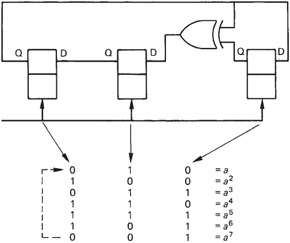
Figure 3.28: The bit patterns of a Galois field expressed as powers of the primitive element a . This diagram can be used as a form of log table in order to multiply binary numbers. Instead of an actual multiplication, the appropriate powers of a are simply added.
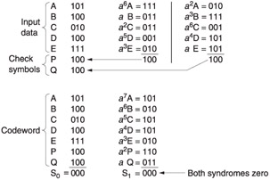
Figure 3.29: Five data symbols AE are used as terms in the generator polynomials derived in Appendix 3.1 to calculate two redundant symbols P and Q. An example is shown at the top. Below is the result of using the codeword symbols AQ as terms in the checking polynomials. As there is no error, both syndromes are zero.
The Galois field shown in Figure 3.28 has been used, having the primitive element a = 010. At the beginning of the calculation of P, the symbol A is multiplied by a 6 . This is done by converting A to a power of a . According to Figure 3.28, 101 a 6 and so the product will be a (6 + 6) = a 12 = a 5 = 111. In the same way, B is multiplied by a , and so on, and the products are added modulo-2. A similar process is used to calculate Q.
Figure 3.29 also demonstrates that the codeword satisfies the checking equations. The modulo-2 sum of the seven symbols, S , is 000 because each column has an even number of ones. The calculation of S 1 requires multiplication by descending powers of a . The modulo-2 sum of the products is again zero. These calculations confirm that the redundancy calculation was properly carried out.
Figure 3.30 gives three examples of error correction based on this codeword. The erroneous symbol is marked with a dash. As there has been an error, the syndromes S and S 1 will not be zero.
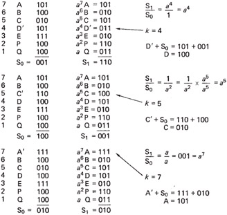
Figure 3.30: Three examples of error location and correction. The number of bits in error in a symbol is irrelevant; if all three were wrong, S would be 111, but correction is still possible.
| | ||
| | ||
| | ||
EAN: 2147483647
Pages: 120
- Chapter I e-Search: A Conceptual Framework of Online Consumer Behavior
- Chapter II Information Search on the Internet: A Causal Model
- Chapter III Two Models of Online Patronage: Why Do Consumers Shop on the Internet?
- Chapter XI User Satisfaction with Web Portals: An Empirical Study
- Chapter XVI Turning Web Surfers into Loyal Customers: Cognitive Lock-In Through Interface Design and Web Site Usability