The Basics
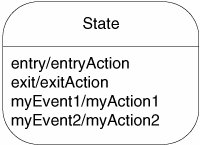
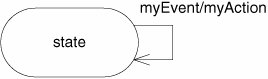
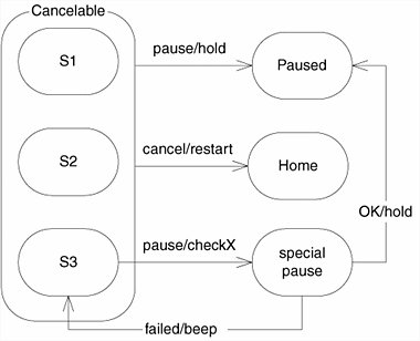
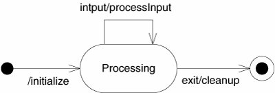
| Figure 15-1 shows a simple state transition diagram (STD) that describes an FSM that controls the way a user logs in to a system. The rounded rectangles represent states. The name of each state is in its upper compartment. In the lower compartment are special actions that tell us what to do when the state is entered or exited. For example, as we enter the Prompting for Login state, we invoke the showLoginScreen action. When we exit that state, we invoke the hideLoginScreen action. Figure 15-1. Simple login state machine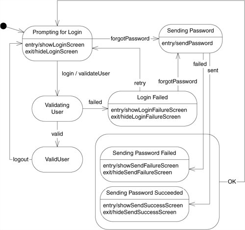 The arrows between the states are called transitions. Each is labeled with the name of the event that triggers the transition. Some are also labeled with an action to be performed when the transition is triggered. For example, if we are in the Prompting for Login state and get a login event, we transition to the Validating User state and invoke the validateUser action. The black circle in the upper left of the diagram is called an initial pseudostate. An FSM begins its life following the transition out of this pseudostate. Thus, our state machine starts out transitioning into the Prompting for Login state. I drew a superstate around the Sending Password Failed and Sending Password Succeeded states because both states react to the OK event by transitioning to the Prompting for Login state. I didn't want to draw two identical arrows, so I used the convenience of a superstate. This FSM makes it clear how the login process works and breaks the process down into nice little functions. If we implement all the action functions such as showLoginScreen, validateUser, and sendPassword, and wire them up with the logic shown in the diagram, we can be sure that the login process will work. Special EventsThe lower compartment of a state contains event/action pairs. The enTRy and exit events are standard, but as you can see from Figure 15-2, you can supply your own events, if you like. If one of these special events occurs while the FSM is in that state, then the corresponding action is invoked. Figure 15-2. States and special events in UML Before UML, I used to represent a special event as a transition arrow that looped around back to the same state, as in Figure 15-3. However, this has a slightly different meaning in UML. Any transition that exits a state will invoke the exit action, if any. Likewise, any transition that enters a state will invoke the enTRy action, if any. Thus, in UML, a reflexive transition, such as that in Figure 15-3, invokes not only myAction but also the exit and enTRy actions. Figure 15-3. Reflexive transition SuperstatesAs you saw in the login FSM in Figure 15-1, superstates are convenient when you have many states that respond to some of the same events in the same way. You can draw a superstate around those similar states and simply draw the transition arrows leaving the superstate instead of leaving the individual states. Thus, the two diagrams in Figure 15-4 are equivalent. Figure 15-4. Transition: multiple states and superstate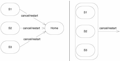 Superstate transitions can be overridden by drawing explicit transition from the substates. Thus, in Figure 15-5, the pause TRansition for S3 overrides the default pause transition for the Cancelable superstate. In this sense, a superstate is rather like a base class. Substates can override their superstate transitions the same way that derived classes can override their base class methods. However, it is inadvisable to push this metaphor too far. The relationship between superstates and substates is not really equivalent to inheritance. Figure 15-5. Overriding superstate transitions Superstates can have entry, exit, and special events the same way that normal states can have them. Figure 15-6 shows an FSM in which both superstates and substates have exit and entry actions. As it transitions from Some State into Sub, the FSM first invokes the enterSuper action, followed by the enterSub action. Likewise, if it transitions out of Sub2 back to Some State, the FSM first invokes exitSub2 and then exitSuper. However, since it does not exit the superstate, the e2 transition from Sub to Sub2 simply invokes exitSub and enterSub2. Figure 15-6. Hierarchical invocation of entry and exit actions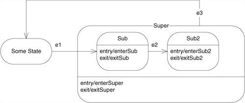 Initial and Final PseudostatesFigure 15-7 shows two pseudostates that are commonly used in UML. FSMs come into existence in the process of transitioning out of the initial pseudostate. The transition leading out of the initial pseudostate cannot have an event, since the event is the creation of the state machine. The transition can, however, have an action. This action will be the first action invoked after the creation of the FSM. Figure 15-7. Initial and final pseudostates Similarly, an FSM dies in the process of transitioning into the final pseudostate. The final pseudostate is never actually reached. Any action on the transition into the final pseudostate will be the last action invoked by the FSM. |

EAN: 2147483647
Pages: 272