Chapter 16. Cameras and Rendering
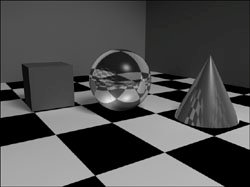
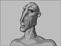
Creating images in Maya, whether for print or video, depends on
rendering
. When you render a scene, you create a two-dimensional image based on a specified three-dimensional view of your scene. Maya does
Figure 16.1. Even these simple primitives look more like real objects when they're rendered.
Figure 16.2. Maya 7's new toon rendering features allow you to create the illusion of hand-drawn, cel-shaded images and animations.
Maya comes with four different renderers: Maya Software, Maya Hardware, Maya Vector, and Mental Ray. Each of these renderers uses a different method to generate an image from a Maya scene. Because certain effects can only be created with a specific renderer, it's important to know the capabilities of each one. Each renderer has its own settings, which you can view and change in the Render Settings window, along with the common render settings. |
About
|
|
1. |
Choose Create > Cameras > Camera.
Figure 16.4. When a new camera is created, it appears at the origin.
|
|
2. |
Use the Move and Rotate tools to adjust the camera's position and angle.
|
|
3. |
From the Panels menu in the Perspective view, select Look Through Selected.
Figure 16.5. The camera has been moved and
|
|
4. |
Dolly, track, and tumble to further adjust the camera's placement.
|
Tips
To create and adjust a camera and aim:
|
1. |
Choose Create > Cameras > Camera and Aim.
Figure 16.7. A camera and aim has been created. The aim is represented by a small circle with a dot in the middle.
|
|
2. |
|
|
3. |
In the Outliner, select the
Figure 16.8. Click to select the camera group in the Outliner.
|
|
4. |
Move the camera group.
|
|
5. |
In the Perspective view, select and then move the aim.
|
|
6. |
In the Perspective view, select and then move the camera.
|
The camera moves, but it continues to point at the aim ( Figure 16.9 ).
Tip
You can change whether the camera has an aim or aim and up control after the camera has been created. Select the camera and open the Attribute Editor, and then expand the Camera Attributes section if necessary. You can choose among the three types of cameras from the Controls drop-down menu ( Figure 16.10 ).
By animating a camera, you can simulate the camera motion used in real-world film or create fly-throughs and other shots that would be
Animating a camera is, in essence, the same as animating anything else: You select it, keyframe it, change the current time, move it, and keyframe it again. It's often
One point you need to understand before you begin animating is that the selected camera isn't
To animate the camera using tumble, track, and dolly:
|
1. |
Create some objects, and arrange them in the scene so you have something to look at.
|
|
2. |
From the View menu in the Perspective view, choose Select Camera (
Figure 16.12
).
Figure 16.12. You can select a view's camera from its View menu.
|
|
3. |
Press
|
|
4. |
In the Time Slider, change the current frame to 30 by clicking the number 30 (
Figure 16.13
).
Figure 16.13. Click 30 in the Time Slider to move to frame 30.
|
|
5. |
Tumble, track, and dolly the camera to change the point of view.
|
|
6. |
Press
|
|
7. |
Play the animation by clicking the play button in the timeline
Figure 16.14. When you click play, the view changes over time, reflecting the camera's animation.
|
To make the aim of the camera follow an object:
|
1. |
Choose Create > NURBS Primitives > Sphere.
|
|
2. |
Choose Create > Cameras > Camera and Aim.
|
|
3. |
While the camera and aim are still selected, move them so that the aim control is at the center of the sphere (
Figure 16.15
).
Figure 16.15. When a camera and aim is created, both the camera and its aim are selected, so you can move them together.
|
|
4. |
Select the sphere, and then
|
|
5. |
From the Constrain menu in the Animation menu set, choose Point.
|
|
6. |
Select and move the sphere.
Figure 16.16. Once the camera's aim is point constrained to the sphere, the camera automatically aims at it.
|
To animate a camera along a
|
1. |
Create a row of cones.
|
|
2. |
In the Top view, create a NURBS curve that
Figure 16.17. It's
|
|
3. |
Choose Create > Cameras > Camera.
|
|
4. |
With the camera still selected,
|
|
5. |
Choose Animate > Motion Paths > Attach to Motion Path.
Figure 16.18. The camera is attached to this motion path, so it jumps to the beginning of the curve. However, it's
|
|
6. |
With the camera still selected, click motionPath1 in the Inputs section of the Channel Box.
|
|
7. |
Click Up Twist in the Channel Box, and then click and drag with the middle mouse button in the Perspective view until the camera is pointing down the path correctly.
|
|
8. |
Click the play button
Figure 16.19. The camera, now oriented correctly,
|
The
frustum
is the volume of space that can be
Depending on its aspect ratio (which is the ratio between width and height), a view may display a larger area than is encompassed by the camera's frustum. If you want to know what portion of a view will be visible when the scene is rendered, you can
To adjust the clipping planes:
|
1. |
Select the camera.
|
|
2. |
Press
|
|
3. |
Under Camera Attributes, enter a new value for Near Clip Plane or Far Clip Plane.
|
To display the resolution gate:
Adjusting a camera's Focal Length attribute creates a zoom effect, making objects in the view appear larger or smaller. This is different from dollying in and out, because the camera doesn't actually move. Instead, the camera's angle of view gets wider or narrower ( Figure 16.23 ). When the focal length is decreased, the angle gets wider, so more of the scene is visible in the view. Increasing the focal length makes the angle of view narrower so that less of the scene is displayed in the view. Decreasing the focal length also has the effect of exaggerating distances, whereas increasing it flattens them.
To adjust a camera's focal length:
|
1. |
Create a cube at the origin (
Figure 16.24
).
Figure 16.24. This cube appears as usual in the Perspective view, which has a default focal length of 35.
|
|
2. |
From the View menu in the Perspective view, choose Select Camera.
|
|
3. |
In the Channel Box, change Focal Length to 10.
Figure 16.25. With the focal length set to 10, the cube seems much further away, even though the camera hasn't moved.
|
|
4. |
Dolly the camera in toward the object.
Figure 16.26. The camera has been moved close to the cube, with the focal length still set to 10. The effect is similar to that of a fisheye lens.
|
A real camera can only focus within a specific range, referred to as its depth of field . Objects that are in focus appear sharp. Objects that are out of focus, either because they're too close to the camera or too far away from it, are blurred. You can re-create this effect in Maya. Depth of field can be useful when you want your rendered image to look like a photograph, or when you're trying to focus the viewer's attention on a specific area of your scene.
To use depth of field:
|
1. |
Create a scene with three spheres and a plane. Move the spheres so that one is close to the camera, one is at the origin of the scene, and one is far away (
Figure 16.27
).
Figure 16.27. These spheres are positioned to display a depth of field effect when rendered.
|
|
2. |
Assign a checkerboard material to the spheres.(See Chapter 14, "Shaders, Materials, and Mapping" for more information.)
|
|
3. |
From the View menu in the Perspective view, choose Select Camera.
|
|
4. |
Open the Channel Box.
|
|
5. |
Set FStop to 32.
|
|
6. |
Set Focus Distance to approximately the same value as Center Of Interest (
Figure 16.28
).
Figure 16.28. The Focus Distance setting allows you to determine where the depth of field effect is centered.
Focus Distance determines the |
|
7. |
Open the Attribute Editor. In the Depth of Field section, select the Depth Of Field check box (
Figure 16.29
).
Figure 16.29. You must enable depth of field for a camera to use the effect.
This option enables depth of field for the camera. |
|
8. |
Choose Render > Render Current Frame.
Figure 16.30. Depth of field causes the sphere
|
An image plane is a component of the camera that remains in the background of the view regardless of how the camera is moved. An image plane can come in handy when you want to use an image as a template for modeling a character. Because image planes are rendered with the scene, you can also use an image plane as a backdrop.
To create an image plane:
|
1. |
From the View menu of the Perspective view, select Image Plane > Import Image.
|
|
2. |
Browse for your image, and click Open.
Figure 16.31. A sky image has been added to the background of this scene. This image plane will stay in the same place relative to the camera even if you tumble, track, or dolly.
|
To position an image plane:
|
1. |
Change the selection mask to Select by Component Type
|
|
2. |
Click the image plane to select it.
|
|
3. |
Open the Channel Box, and adjust the image plane's Offset X and Offset Y attributes (
Figure 16.32
).
Figure 16.32. Increasing the image plane's Offset Y causes it to appear higher in the view.
The image plane is now correctly positioned for your scene ( Figure 16.33 ). Figure 16.33. The sky image is now positioned correctly.
|
Tips
To delete an image plane, select it by following steps 1-2 above, and then press
.
A quick way to hide an image plane is to uncheck Cameras on the view's Show menu. Because the image plane is a component of the camera, the image plane is also hidden.