| Automatic mapping doesn't always produce adequate UVs. Usually you'll need to adjust the UVs by hand before you can shade your model. The UV Texture Editor is a special window for unwrapping, or laying out, your UVs. Using this window, you can translate, scale, rotate, and use a variety of special tools to manipulate the UVs of your model. You navigate the UV Texture Editor just as you would any other panel. Any adjustments made to UVs don't affect the geometry of your model. The image that is mapped to the surface is tiled in the background of the UV Texture Editor. This lets you move different portions of the surface onto the part of the image you want without a lot of messy overlapping. To use the UV Texture Editor: 1. | Continue using the phone from the previous task.
| 2. | With your object selected, choose Window > UV Texture Editor.
The UV Texture Editor opens. You can see the image that was assigned to the surface; on top of it is the wireframe of the different parts of the surface (shells) that have been separated.
| 3. | Right-click the surface, and select UV from the marking menu.
| 4. | Choose one UV point from the center of the earpiece of the telephone (Figure 14.84).
Figure 14.84. One UV point has been selected from the center of the earpiece of the phone. 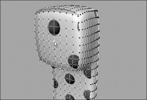
The UV shows up as selected both in the UV Texture Editor and in your normal view panels. UVs are always green when selected.
| 5. | Right-click the shell, and choose Select > Select Shell from the marking menu (Figure 14.85).
Figure 14.85. Rather than having to carefully select each UV of the shell, you can select the whole shell at once by right-clicking and choosing Select > Select Shell from the marking menu. 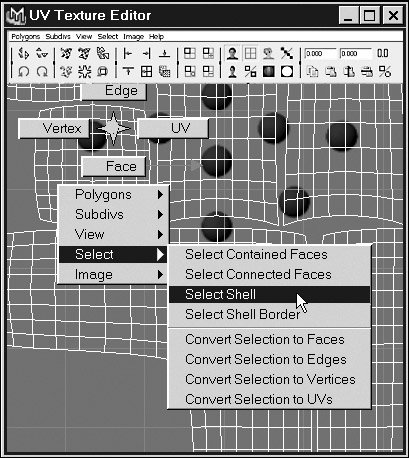
All the UVs of the shell are selected.
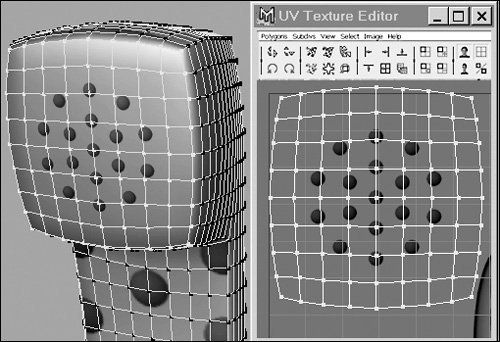
| | | 6. | Move, scale, and rotate the shell over a recognizable part of the image (Figure 14.86).
Figure 14.86. In the UV Texture Editor, you can see how the different parts of the surface have been laid out over the image map. The UV point that was selected in the Perspective view is also selected here and displays move manipulators. This makes it easy to recognize which shell is the phone's earpiece. 
You can watch the image on the selected area of the phone change interactively in the Perspective view.
| 7. | Repeat steps 3-6 for other parts of the phone.
|
 Tip Tip
Because the surface is in many separate pieces (shells) in the UV Texture View, there are seams on the surface (Figure 14.88). You can combine two shells and get rid of the seam by using Move and Sew UVs. Figure 14.88. A seam in the texture is apparent along the side of the phone. 
To eliminate a seam in a texture using Move and Sew UVs: 1. | Continue using the phone from the previous tasks.
| 2. | From the Display menu, choose the box next to Custom Polygon Display.
| | | 3. | Next to Objects Affected, select All, and select Highlight Texture Borders (Figure 14.89).
Figure 14.89. Highlight the texture borders to show your UV shells as thick lines. 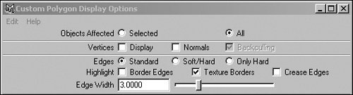
This option displays the seams on your object as thick lines, making them easy to see.
| 4. | In the Perspective view, use the Select Edge Loop tool to select all the edges along the seam (Figure 14.90).
Figure 14.90. All of the polygon edges along the edge of the seam have been carefully selected. 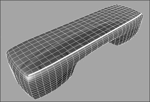
The corresponding edges are automatically selected in the UV Texture Editor when you select them on the object (Figure 14.91).
Figure 14.91. The edges of two shells are selected because they are, in fact, one edge shared by both shells. 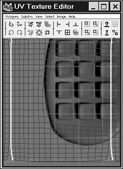
| 5. | Choose Edit Polygons > Texture > Move and Sew UVs.
The seam on the object disappears in the Perspective view (Figure 14.92). In the UV Texture Editor, two shells have been combined along that edge (Figure 14.93).
Figure 14.92. The seam is gone because the edges of the two shells have been sewn together, allowing the texture image to extend across both. 
Figure 14.93. Two separate shells have been joined into one bigger shell covering a larger portion of the phone. 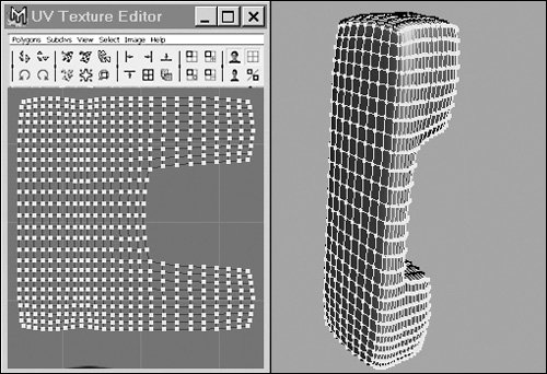
|
Automatic mapping is often a good starting point for laying out your UVs, but it can create many shells. Use Maya's new Unfold option when you want to preserve part of a surface as a single shell (Figure 14.94). Figure 14.94. This face was laid out using the Unfold tool. To minimize seams, it's useful for detailed and visible areas like faces to be one shell. 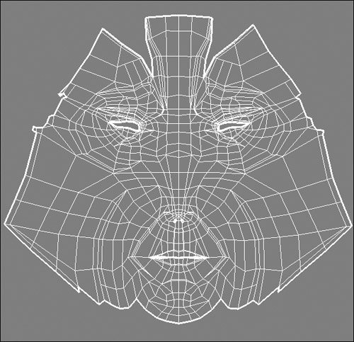
Unfold attempts to unwrap and flatten the UVs of an object, but it requires a bit of preparation in the form of strategically placed seams. To use the unfold tool to map UVs: 1. | Start with the unmapped phone from the previous tasks. You want the seams to be highlighted, so make sure the Highlight Texture Borders option is selected.
| 2. | Choose Polygon UVs > Automatic Mapping, and press  . .
| 3. | Select all the UVs, and click the Sew UVs button  . .
This removes all the seams from your layout so you can insert your own.
| 4. | Use the Select Edge Loop tool to select the edges along the edge of the front of the phone (Figure 14.95).
Figure 14.95. To split the phone into two sections (a front and a back), select all the edges around the front. 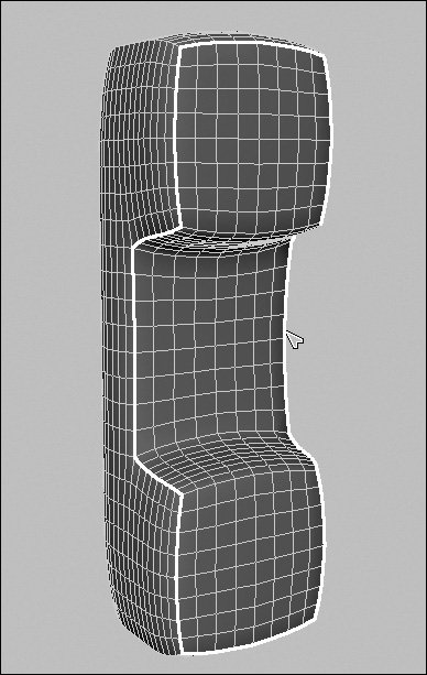
| 5. | Click the button to insert seams at these edges.
| | | 6. | Choose Polygon UVs > Unfold UVs. The UVs are flattened and laid out, but one piece is distorted (Figure 14.96).
Figure 14.96. The back is distorted because it's a concave shape with no seams to fold. It needs to be cut free to unfold properly. 
You may need to reposition and scale your UVs after an unfold.
| 7. | Select the edges on the phone corners, and click (Figure 14.97).
Figure 14.97. Select all four corners of the phone from front to back. 
Now the shape can unfold like a piece of paper with tabs.
| 8. | Choose Polygon UVs > Unfold UVs.
The UVs are now unfolded with less distortion, and they can be scaled and rotated into place (Figure 14.98).
Figure 14.98. The phone now unfolds evenly, as one piece. 
|
Tips Select Pin Selected in the Unfold option if you want to retain the layout of certain UVs. This prevents selected UVs from moving during the unfold operation. You can pin an object's corners or lines of symmetry to force the object to unfold a certain way. For example, aligning the center of a character's face and then pinning it, or pinning the corners of a flag in a square, forces the shape into a logical arrangement.
Using the UV Texture Editor toolbar The UV Texture Editor toolbar holds shortcuts to many of the actions in the UV Texture Editor menus. The toolbar is divided into four main sections: UV Position buttons, Isolate Selection buttons, View buttons, and UV Edit buttons. They provide the following functions: UV Position buttons This section holds shortcuts to many of the UV position tools, including flipping, rotating, sewing, and aligning UVs (Figure 14.99). Figure 14.99. The UV Position buttons section of the UV Texture Editor toolbar. 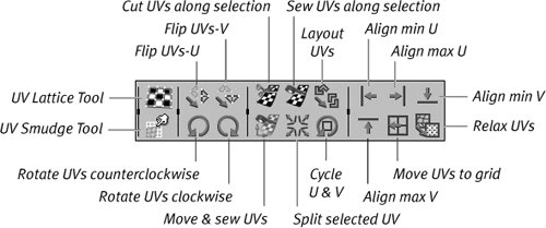 Isolate Selection buttons This section holds shortcuts to adding, removing, and toggling isolation tools (Figure 14.100). Figure 14.100. The Isolate Selection buttons section of the UV Texture Editor toolbar. 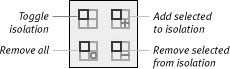 View buttons This section holds snaps, toggles, and border menu shortcuts (Figure 14.101). Figure 14.101. The View buttons section of the UV Texture Editor toolbar. 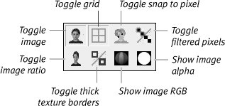 UV Edit buttons This section holds UV coordinate input fields as well as UV copying and pasting features (Figure 14.102). Figure 14.102. The UV Edit buttons section of the UV Texture Editor toolbar. 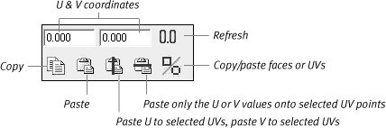
About projecting UV maps Earlier in this chapter, you were shown how to project a texture; you can also project UV maps. One main difference is that a projected UV map sticks to the object even if it deforms, whereas a deforming object will "swim" through a projected texture. To create a planar UV map for a polygon object: 1. | Open the model of the polygon telephone you made in the first step of the task "To create automatic mapping for a polygon texture" earlier in this chapter.
| 2. | Open the Hypershade, create a blinn material, and assign it to the surface.
| 3. | Double-click the blinn material in the Hypershade.
The Attribute Editor for the blinn material opens.
| 4. | Click the Map button  next to the Color slider. next to the Color slider.
The Create Render Node window appears.
| 5. | Make sure that Normal is selected, and then click Checker.
| 6. | Select the phone surface, and, from the Polygon UVs menu, select the box next to Planar Mapping.
The Polygon Planar Projection Options dialog box opens (Figure 14.103).
Figure 14.103. Use the Polygon Planar Projection Options dialog box to control how the object is mapped. 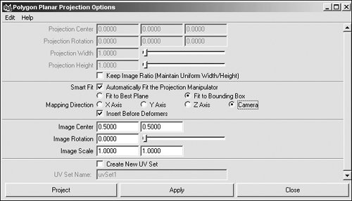
| 7. | For Mapping Direction, click Camera, and click Apply.
A projected mapping manipulator appears around the object (Figure 14.104).
Figure 14.104. The projected mapping manipulator appears around the object. 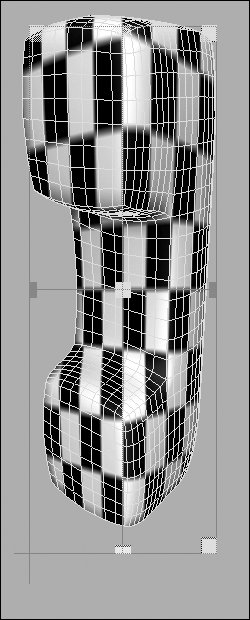
| | | 8. | Rotate the camera by pressing  while you click and drag in the 3D view. while you click and drag in the 3D view.
The texture stretches across the object from the camera's previous position (Figure 14.105).
Figure 14.105. Rotating the camera reveals that the texture was projected from the camera's previous point of view (POV). 
| 9. | In the Polygon Planar Projection Options dialog box, click Apply again.
The projected mapping manipulator changes position to match the camera's current direction (Figure 14.106).
Figure 14.106. The projected mapping manipulator updates to match the current camera POV. 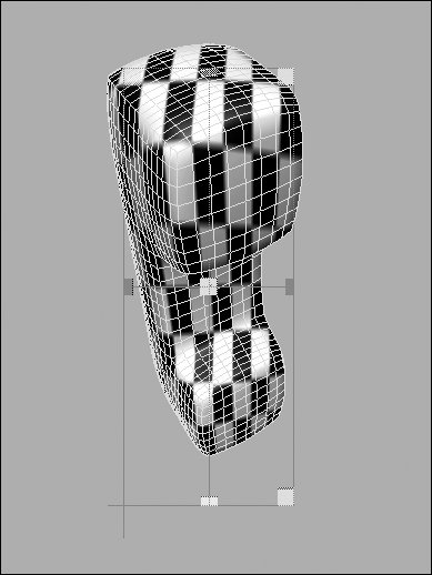
Using the camera option forces the projection to be created from the camera's current view.
| 10. | In the Mapping Direction section of the Polygon Planar Projection Options dialog box, click Y Axis, and click Apply.
The projected mapping manipulator changes position so that it projects directly down the y. axis (Figure 14.107).
Figure 14.107. The projected mapping manipulator projects down the y axis. 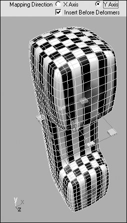
| | | 11. | Repeat step 10, but click the Z Axis button to project down the z axis (Figure 14.108) or click the X Axis button to project down the x axis (Figure 14.109).
Figure 14.108. Projecting down the z axis. 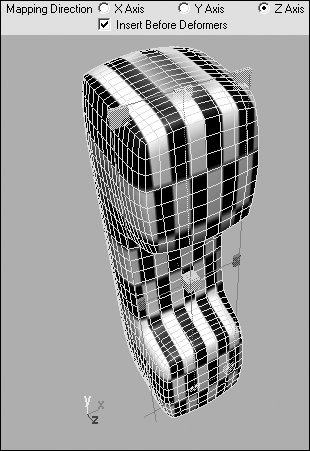
Figure 14.109. Projecting down the x axis. 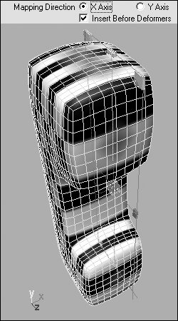
| 12. | Click and drag the green box on the texture projection manipulator.
This scales the manipulator and allows additional control over the placement of a UV projection (Figure 14.110).
Figure 14.110. Drag the handles on the projected mapping manipulator to change its scale and position. 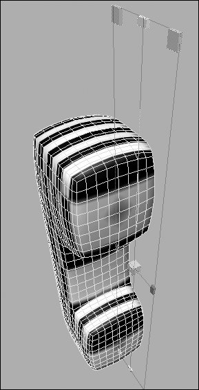
| 13. | Switch to selection-by-hierarchy mode  , and select the phone. , and select the phone.
| 14. | Choose Deform > Create Nonlinear > Bend.
This applies a bend deformer to the object.
| | | 15. | In the Inputs section of the Channel Box, click bend1 to reveal the bend controls (Figure 14.111).
Figure 14.111. Apply a bend deformer, and then expand the bend1 options under the Inputs section of the Channel Box. 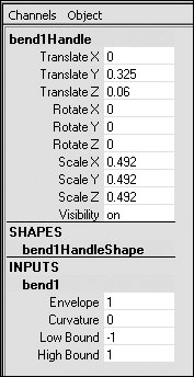
| 16. | Using the middle mouse button, click and drag Curvature back and forth in the 3D view to set the value to .5.
or
In the numeric entry field, set Curvature to .5.
The texture sticks to the object as the object deforms (Figure 14.112).
Figure 14.112. The object deforms, and the texture sticks to it. 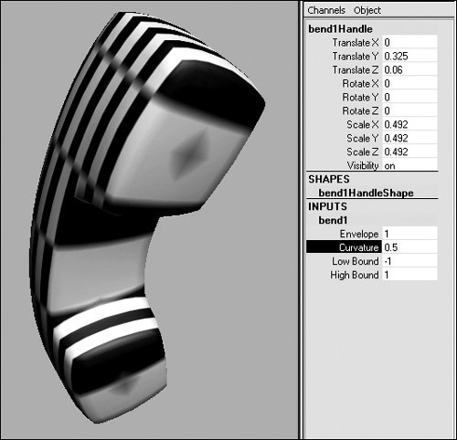
| 17. | Deselect Insert Before Deformers, and click Apply again.
The mapping changes to reflect the deformation of the object (Figure 14.113).
Figure 14.113. Deselect Insert Before Deformers to allow the mapping to be applied to the object in its current deformed shape. 
|
To create a cylindrical UV map for a polygon object: 1. | Repeat steps 1-5 from the previous task, "To create a planar UV map for a polygon object."
| 2. | Select the phone surface, choose Edit Polygons > Texture, and select the box next to Cylindrical Mapping.
The Polygon Cylindrical Projection Options dialog box opens (Figure 14.114).
Figure 14.114. The Polygon Cylindrical Projection Options dialog box. 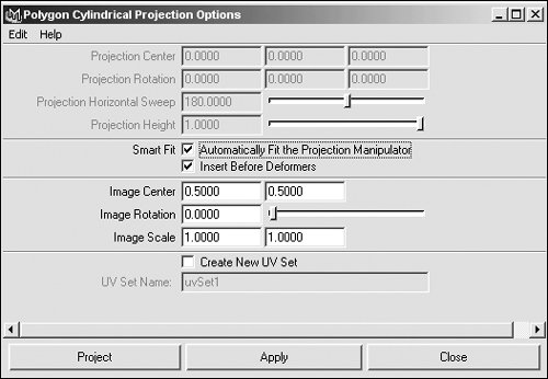
| 3. | Click Apply to accept the default values and update mapping on the surface (Figure 14.115).
Figure 14.115. The mapping on the object updates, and the projected mapping manipulator appears. 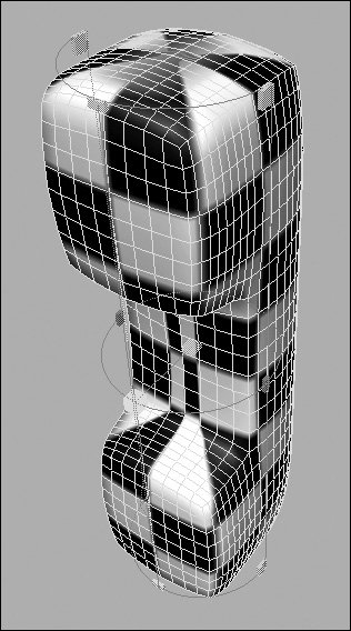
| | | 4. | In the first numeric entry field, set Image Scale to .5; then, click Apply (Figure 14.116).
Figure 14.116. Type a lower value into the Image Scale field to force the texture to be larger in relationship to the object. 
The mapping updates so that the texture around the object is larger.
| 5. | Click and drag the red box on the texture projection manipulator to make the texture around the object larger or smaller (Figure 14.117).
Figure 14.117. Drag the handles on the projected mapping manipulator to control the position and scale of the projection in relationship to the object. 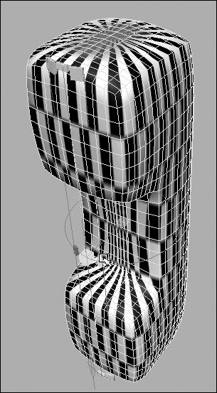
|
To create a spherical UV map for a polygon object: 1. | Repeat steps 1-5 from the task "To create a planar UV map for a polygon object," earlier in this chapter.
| 2. | Select the phone surface, choose Edit Polygons > Texture, and select the box next to Spherical Mapping.
The Polygon Spherical Projection Options dialog box opens (Figure 14.118).
Figure 14.118. The Polygon Spherical Projection Options dialog box. 
| | | 3. | Click Apply to accept the default values and update mapping on the surface (Figure 14.119).
Figure 14.119. The mapping on the object updates, and the projected mapping manipulator appears. 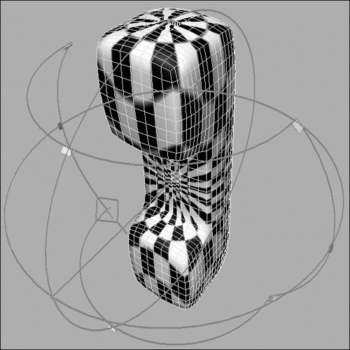
| 4. | Click and drag the blue box on the texture projection manipulator to make the texture around the object smaller (Figure 14.120) or larger (Figure 14.121).
Figure 14.120. Drag the handles on the projected mapping manipulator to scale the projection and make it smaller... 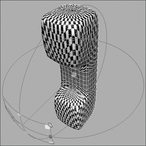
Figure 14.121. ...or larger. 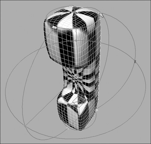
|
Texturing Subdivs Texturing subdiv surfaces is very similar to texturing polygons; and, under some circumstances, it can be done exactly the same way. For instance, several of the UV commands can be found in the Subdiv Surfaces > Texture menu option, and these commands function like their poly equivalents. However, in subdiv mode, the UVs correspond directly to the CVsnot the surface points. Additionally, you can't edit the UV mapping of a subdiv by switching to polygon mode. If you do, you'll lose any UV data adjusted in Subdiv mode. Instead, choose Modify > Convert > Convert to Subdiv Options to open the Convert to Subdiv Options dialog box. Then, select Proxy Object Subdivision Surface Mode. When you edit the UV mapping on the polygon cage, it will update UV mapping on the subdiv surface. |
|