| A cluster provides a means of controlling a set of points as a group. The points can be NURBS control vertices (CVs), polygon vertices, or lattice points. (For more information on these elements, see Chapter 4, "Selection Modes, Hiding, and Templating.") Points that are members of a cluster have weight. As mentioned earlier, weight represents the amount of influence the cluster has over the points it contains. Weight is generally set between 0 and 1. A point with a weight of 0 will not move with the cluster. A point with a weight of 1 will move exactly as much as the cluster itself. Anything in between will make the point move a fraction of how much the cluster moves. For example, suppose a CV in a cluster had a weight of 0.5. If the cluster was moved up two grid units in the Y direction, the CV would move only one unit (Figure 11.7). Simply multiply the weight by the distance the cluster moves, and you'll get the distance the point moves. Figure 11.7. A cluster is made with one CV whose weight is set to 0.5which means the point moves only half the distance of the cluster (right). 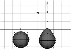
Clusters represent a convenient way of animating portions of a surface. For example, if you wanted to animate the movement of a character's fat belly, you could make a cluster out of the points that form his belly, add different weights to the points on his belly, and then animate that cluster (Figure 11.8). Figure 11.8. The points that make up the belly are included in a cluster. That cluster is parented to the belly and animated to make it bouncy. 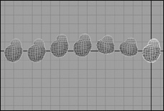
Understanding clusters is also the key to understanding binding. What binding does, in the background, is create clusters of portions of your surface and then parent those clusters to the joints. Once the surface has been bound, you can adjust the weight of the points to get the surface to deform the way you desire. When you understand parenting, clusters, and weight, binding will no longer seem mysterious. To create a cluster: 1. | From the Create menu, select NURBS Primitives > Plane.
| 2. | Select makeNurbPlane1 from the Inputs section of the Channel Box (Figure 11.9).
Figure 11.9. When you click makeNurbPlane1 in the Channel Box, it will expand these options. 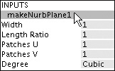
| 3. | Increase Patches U and Patches V to 30.
The plane becomes more dense (Figure 11.10).
Figure 11.10. At the bottom is the plane before the patches were increased. At the top is the plane after the patches have been increased. 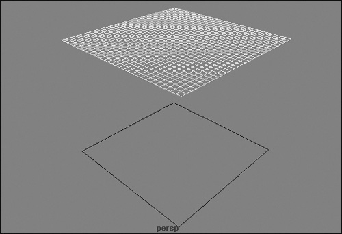
| 4. | Press  to switch to component mode. to switch to component mode.
| 5. | Select some points in the center of the plane (Figure 11.11).
Figure 11.11. The plane is dense, so it has many points. The CVs in the center have been selected so that they can be made into a cluster. 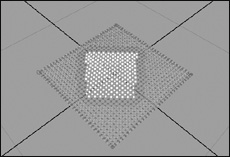
| 6. | From the Deform menu, select Create Cluster.
A C appears in the middle of the selected points.
| 7. | Press  to activate the Move tool and then click and drag to move the cluster. to activate the Move tool and then click and drag to move the cluster.
The CVs move with it (Figure 11.12).
Figure 11.12. The cluster, which is represented by a C, has been moved up. The CVs, which are members of the cluster, move with it, forming a plateau. 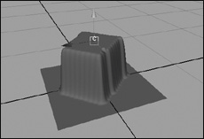
|
To weight the points of a cluster using the Component Editor: 1. | Using the cluster created in the previous task, "To create a cluster," select some of the CVs that are included in the cluster (Figure 11.13).
Figure 11.13. Some of the CVs on the side of the cluster have been selected so that their weights can be changed. 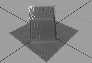
| 2. | From the Window menu, select General Editors > Component Editor.
The Component Editor dialog box appears.
| 3. | Select the Weighted Deformers Tab in the Component Editor (Figure 11.14).
Figure 11.14. In the Component Editor, a cluster is referred to as a Weighted Deformer. The weights of the selected points show up when this tab is selected. 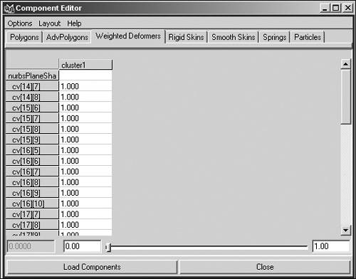
| 4. | Click the top numeric field and drag down to highlight all of the weights.
| 5. | Type .5 in the field, and press  . .
All of the weights in that column become 0.5 (Figure 11.15).
Figure 11.15. On the right, the Component Editor shows that the weights of the selected points have been reduced to 0.5. On the left, the selected points are only moved up half the distance of the cluster because of their lower weight. 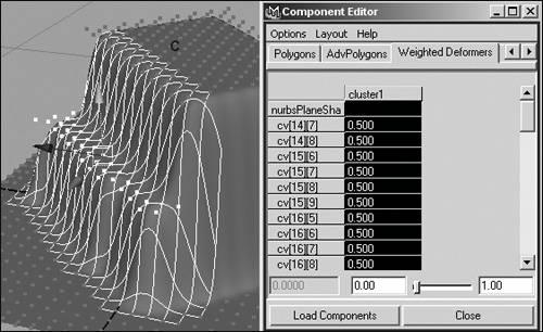
or
Click and drag a range of CVs and use the slider at the bottom of the Component Editor to change the weights interactively.
|
About the Paint Attributes tool Another way of adjusting the weights of a cluster is by using the Paint Attributes tool. Especially handy for working with dense surfaces, this tool includes several options for interactively changing the weight of points (Figure 11.16). Figure 11.16. The Paint Attributes tool can be used to interactively change the weights of points. The options shown here control how the weight is changed. 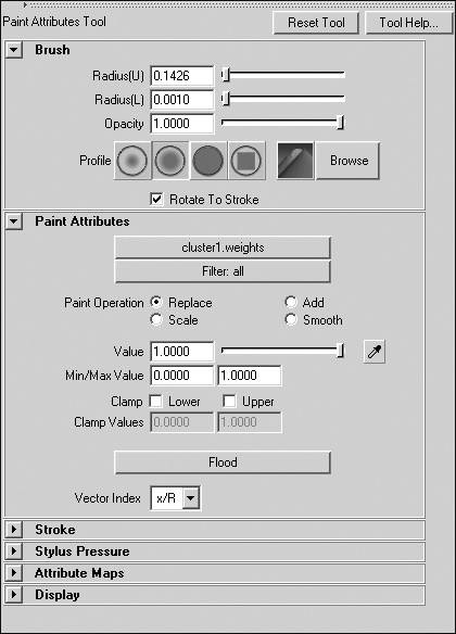
There are four settings for Paint Operations: Replace When Paint Operation is set to Replace, the current weight of the painted points will change to whatever number is set in the Value field. Add When Paint Operation is set to Add, the value will be added to the weight of the painted points. This is useful for incrementally increasing the weights of points. Scale When Paint Operation is set to Scale, the current weight of a point will be multiplied by the value when it is painted. If you have a value of 0.9, you can incrementally decrease the weight of a point. Smooth This averages the weights of the adjacent points to make the area smoother. The Flood button can speed work considerably, because rather than have to paint on an effect, you can have the Paint Attributes tool's settings affect all of the points simultaneously by pressing Flood. This is useful when you're setting all points to the same weight or smoothing all points.
To edit cluster weights using the Paint Attributes tool: 1. | Create a cluster and move it up, as in the previous tasks.
| 2. | Select the surface.
| 3. | Right-click the surface, and select Paint > cluster > cluster1-weights from the Marketing menu (Figure 11.17).
Figure 11.17. Using the Marking Menu, which pops up when you right-click the surface, is the most convenient way to access the Paint Attributes tool. 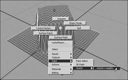
This activates the Paint Attributes tool, which should provide color feedback in shaded mode. The area of the surface that includes CVs in the cluster turns white; the rest appears black.
| 4. | Hold down  and drag the mouse from right to left to shrink the brush size (Figure 11.18). and drag the mouse from right to left to shrink the brush size (Figure 11.18).
Figure 11.18. The brush size started out much too big for this small surface. Here we see the progression as the brush size gets smaller. 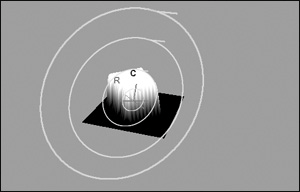
| 5. | Double-click the Paint Attributes tool in the toolbox.
The Tool Settings dialog box for the Paint Attributes tool appears.
| 6. | Change Value to 0.5.
Paint Operation should already be set to Replace (Figure 11.19).
Figure 11.19. Using Replace with a value of 0.5 will bring about the same result as if you had typed it in as the weight in the Component Editor. 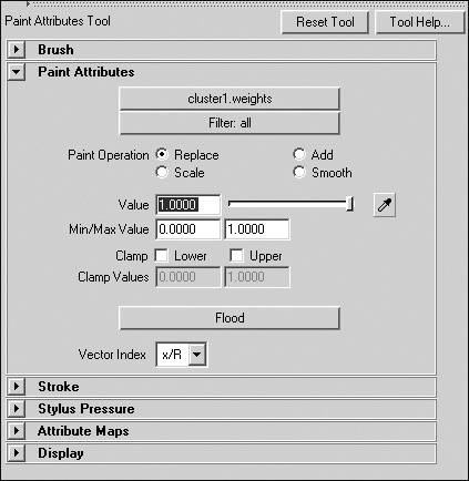
| 7. | Click and drag on the surface.
The painted portion moves down because the weight of the points has been changed to 0.5.
| 8. | Change Paint Operation to Smooth.
| 9. | Click Flood several times.
The lump becomes smooth (Figure 11.20).
Figure 11.20. Flood will apply the current Paint Operation setting to all members of the cluster. In this case, it's set to Smooth so that all the points are smoothed simultaneously when you click Flood, which is quicker than having to paint the surface. 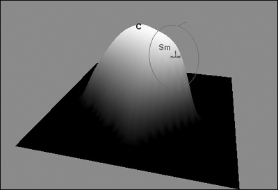
|
|


