| By learning how to create and edit curves, you'll gain a better understanding of how to take full advantage of Maya's modeling tools. Multiple edit points give you precise control over the shape and placement of NURBS curves. Curves are often used to create a wire representation of a surface. Once you've done this, you can place a skin over the curves to create the final surface (Figure 7.6). You can create this final surface using a number of Maya commands, including lofting, extruding, and revolvingall of which we'll examine in depth in this chapter. Figure 7.6. Curves used to create a framework for the surface (top), and the same curves with a surface laid over them (bottom). 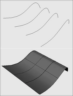
Anatomy of a curve Each NURBS curve has an associated direction, derived from the order in which the CVs were created. A curve's direction is important in determining the look of the final surface. If you don't pay attention to the direction in which a curve is created, you will often get undesirable results when you go to create the final surface. Curves that are oriented in opposite directions can twist and fold the final surface. The direction of a curve is determined by the first and second CVs created for the curve. The first CV, or start point, is represented by a small square. The second CV is represented by the letter U. The start point followed by the U shows the user the direction in which the curve is headed; this determines the U direction of any surface created from the curve (Figure 7.7). Figure 7.7. The U direction of a curve is determined by the first and second CVs created. 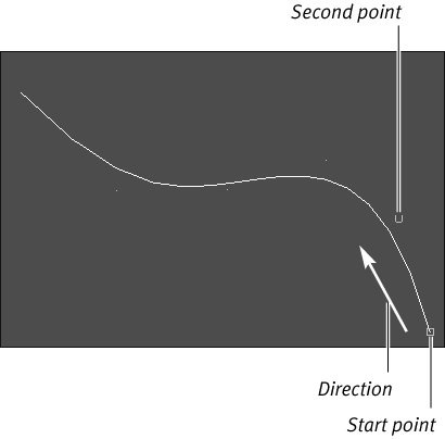
Because NURBS curves are used mainly as modeling aids, they don't appear when the scene is rendered. Each curve has the following components (Figure 7.8): Control vertices CVs are points placed slightly away from the curve and are the components most often used to edit a curve's shape. Edit points (knots) Edit points, placed directly on the curve and indicated by a small x, represent another way of editing a curve's shape. Hulls Hulls are straight lines connecting each CV. Showing the hulls can help clarify which row of CVs each CV is connected to. By clicking a hull, you select the entire row of CVs along the hull. Spans A span is the area between two edit points. Each time an edit point is added, a span is added as well. You can't edit spans directly (like edit points); instead, they represent the results of your edits. You use spans to create and rebuild curves and surfaces. The more spans you add when rebuilding a surface, the more edit points you're addingwhich means the more spans you have, the more detailed, and heavy, your surface becomes. Curve point A curve point is an arbitrary point on a curveoften used as a point to detach a curve from or to align it with. A curve point can be located anywhere along a curve. Start point The start of a curve is the first CV created for the curve, represented by a small square. Curve direction The direction of a curve is determined by the first and second CVs created for the curve. Figure 7.8. This image shows NURBS curve components. 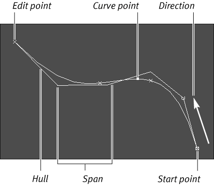
Creating curves of various degrees Every curve has a certain degree; the higher the degree, the smoother the curve. A curve can have a degree of 1, 2, 3, 5, or 7. A curve with a degree of 1 is a linear curve and only requires two points to define it (Figure 7.9). Linear curves and surfaces are characterized by straight lines and sharp corners. A curve degree of 3 will produce a smooth curve without using an excessive number of CVs to describe it (Figure 7.10). A curve with a degree of 3 is the most common and versatile curve because it only requires four points and is smooth enough to create a high-quality surface. Because of the accuracy needed for manufacturing, car designers often use degrees higher than 5. For animation, however, a degree of 3 is usually high enough. Figure 7.9. A curve degree of 1 creates a linear curve and a linear surface (if a surface is created from the curve). 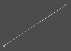
Figure 7.10. A curve degree of 3 produces a smooth curve without using an excessive number of CVs. 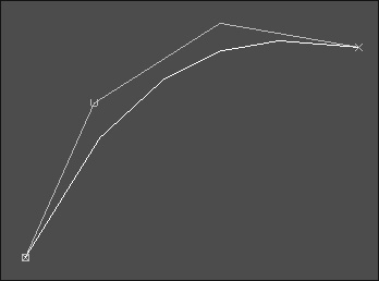
Each curve requires CVs that total one more than its degree to create it. For example, a curve with a degree of 3 requires four CVs (Figure 7.10), and a 7-degree curve requires eight CVs, thereby creating a heavier surface (Figure 7.11). It is for this reason that a degree of 3 or 5 is usually most ideal. Figure 7.11. This is a 7-degree curve, which means it requires eight CVs. 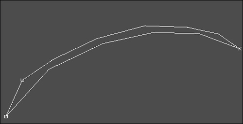
Creating profile curves You can create many objects by drawing an outline curve in the shape of the object's profile. This profile curve can then be revolved to complete the final surface (Figure 7.12). In addition, you can alter the profile curve to tweak the object's shape after the final surface has been created. You can do this because the profile curve and final surface are connected through the object's construction history (Figure 7.13). Figure 7.12. This surface was created with one revolved curve. 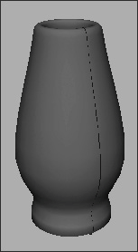
Figure 7.13. By tweaking a point of the curvewhich is how this revolved surface was createdyou can interactively sculpt the object. 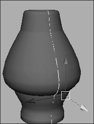
If you're drawing a profile curve for a vase, glass, pot, or any other object that has thickness to it, you should draw the profile of the inside as well as of the outside (Figure 7.14). If you don't draw both profiles, your object will be paper-thin: Since most real objects have some depth or dimension, you need to re-create that thickness in Maya to keep your objects looking realistic. The thickness of the glass is defined by the way you draw the profile curve. Figure 7.14. When drawing a profile curve, make sure you add the inside of the surface to add thickness to the final object. 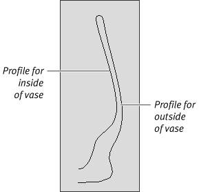
Typically, you create a curve in one of three ways: with the CV Curve tool, the EP Curve tool, or the Pencil Curve tool. To create a curve with the CV Curve tool: 1. | From the Create menu, select CV Curve Tool.
| 2. | In the Top view, click in several places.
A CV will appear with each mouse click, and a curve will appear on the fourth click (Figure 7.15).
Figure 7.15. This curve was created by placing points using the CV Curve tool. 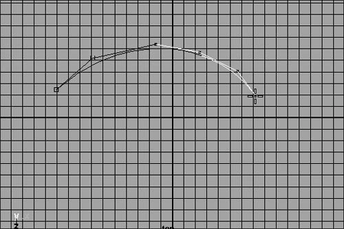
| 3. | Press  to complete the creation of the curve. to complete the creation of the curve.
The curve becomes highlighted to indicate that it's selected.
|
To create a curve with the EP Curve tool: 1. | From the Create menu, select EP Curve Tool.
| 2. | In the Top view, click in several places.
A curve is created once the second edit point is placed, and it continues to take shape with each subsequent point (Figure 7.16).
Figure 7.16. This curve was created using the EP Curve tool. 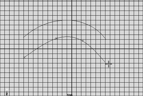
| 3. | Press  to finish creating the curve. to finish creating the curve.
|
To create a curve with the Pencil Curve tool: 1. | From the Create menu, select Pencil Curve Tool.
| 2. | Click and drag in the Top view to draw a line.
The curve is completed once you release the mouse. The Pencil Curve tool tends to be a less efficient way of creating a curve because you end up with more points than you need to describe the shape (Figure 7.17).
Figure 7.17. The bottom curve was created using the Pencil Curve tool. 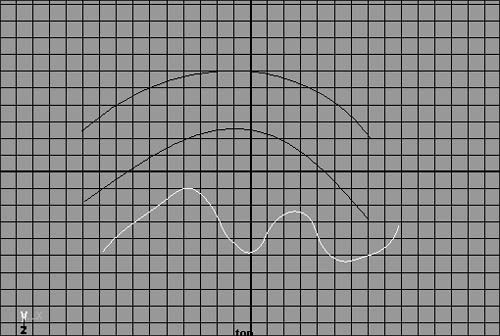
|
As stated earlier, each curve has a direction, called the U direction. Sometimes you'll want to reverse a curve's direction because you are getting undesirable surfaces from the curves (Figure 7.18). Figure 7.18. Curve direction can cause unwanted surface problems. It is best to keep all curves of the same surface facing in the same direction. 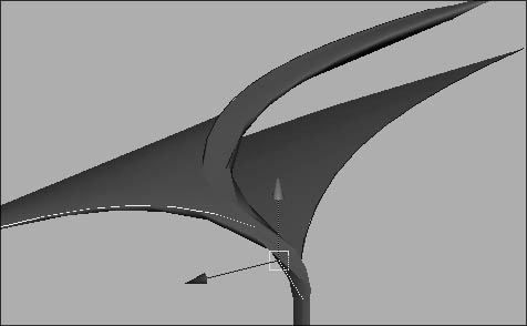
To reverse a curve's direction: 1. | Select a curve in object mode.
| 2. | From the Edit Curves menu, select Reverse Curve Direction (Figure 7.19).
Figure 7.19. Select Edit Curves > Reverse Curve Direction to change the direction of a curve. 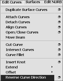
| 3. | Press  to view the new curve direction in component mode (Figure 7.20). to view the new curve direction in component mode (Figure 7.20).
Figure 7.20. The curve on top shows the direction before it was reversed; the curve beneath it shows the direction after the curve has been reversed. 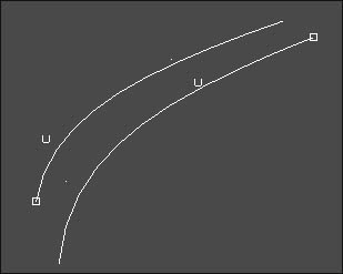
|
Circular 2D fillets A fillet is a concave junction where two curves or surfaces meet. You can create 2D fillets to combine multiple curves with an arc between them. Sometimes it's easier to create two curves and fillet them together in order to create a corner than it is to draw out one curve with the corner in it. An example might be when you need to create a corner out of two perpendicular curves (Figure 7.21). Figure 7.21. A 2D fillet serves as a good tool for adding smooth corners to a set of curves. 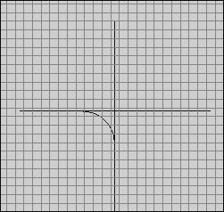
To create a circular 2D fillet: 1. | Create two curves to fillet between (Figure 7.22).
Figure 7.22. Two curves are intersecting. 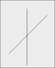
| 2. | Right-click the first curve and select Curve Point from the Marking menu (Figure 7.23).
Figure 7.23. A Marking menu appears when you click the curve with your right mouse button. This is a convenient way to choose which component type you'd like to be able to select. 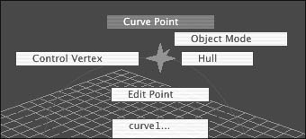
| 3. | Click the first curve, and drag the point to where you want the fillet to arc (Figure 7.24).
Figure 7.24. Click and drag a curve point into the place where you would like the arc to begin. 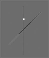
| 4. | Right-click the second curve and select Curve Point from the Marking menu.
| 5. |  -click the second curve and drag the point to where you want the fillet to arc (Figure 7.25). -click the second curve and drag the point to where you want the fillet to arc (Figure 7.25).
Figure 7.25. The two curve points determine the start and end points of the arc. 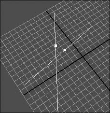
| 6. | From the Edit Curves menu, select Curve Fillet.
An arc is created between the two curve points (Figure 7.26).
Figure 7.26. An arc is created between the two curve points selected on each curve. 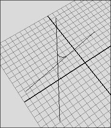
|
Opening and closing curves A curve that does not start and end on the same point is called an open curve (Figure 7.27). Many Maya commands will not function correctly on open curves, so the curves must be closed. A closed curve has the same start and end point, making it continuous (Figure 7.28). Figure 7.27. An incomplete circle is called an open curve. 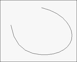
Figure 7.28. A closed curve has the same start and end point. 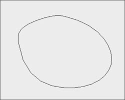
To open or close a curve: From the Edit Curves menu, select Open/Close Curves (Figure 7.29). Figure 7.29. The Open/Close Curves command opens a closed curve and closes an open curve. 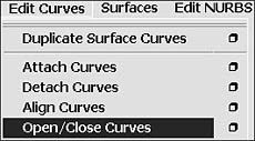
An open curve will become closed, and a closed curve will become open.
To detach a curve: 1. | Select a curve with the Pick mask set to Component: Parm Points mode.
| 2. | Select the edit point x where you would like to detach the curve (Figure 7.30).
Figure 7.30. An edit point is represented by an x; when selected, it can be used as a curve's breaking point. 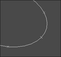
| 3. | From the Edit Curves menu, select Detach Curves.
The curve is now broken into two curves (Figure 7.31).
Figure 7.31. Two curves are created out of the detachment at the edit point. 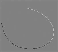
|
 Tip Tip
Locking the length of a curve Curves are like rubber bands in that you can pull and stretch them apart. That is, you can edit CVs to be any distance from one another that you want. However, for the practical purposes of animation, you'd be better off making your curve behave like a piece of string that stays the same length while you bend it. You can do that by locking the length of the curve so that the CVs remain the same distance from one another when you animate the curve. To lock the length of a curve: 1. | Select a curve and choose Edit Curves > Modify Curves > Lock Length (Figure 7.32).
Figure 7.32. Select Edit Curves > Modify Curves > Lock Length. 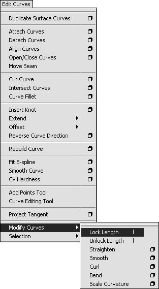
| 2. | Press  to switch to component mode and select the Points component type to switch to component mode and select the Points component type  . .
| 3. | Select the first CV in the curve, press  and move it around. and move it around.
The curve will now follow the CV you selected like a piece of string (Figure 7.33).
Figure 7.33. With Lock Length enabled, drag a CV to animate the curve like a piece of string. 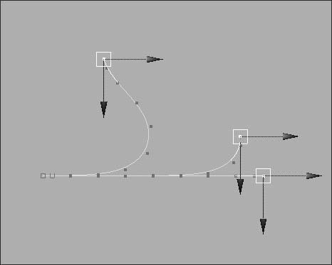
|
 Tip Tip
To straighten a curve: 1. | With a curve selected, choose Edit Curves > Modify Curves and click the option box next to Straighten (Figure 7.34).
Figure 7.34. Select Edit Curves > Modify Curves > Straighten. 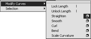
The Straighten Curves Options dialog box opens.
| 2. | Uncheck the Preserve Length check box.
| 3. | Adjust the Straightness slider to 1 (or simply type 1 in the text box) (Figure 7.35).
Figure 7.35. Set the options for Straighten. 
| 4. | Click Apply.
The wavy Curve becomes a straight line (Figure 7.36).
Figure 7.36. The top Curve is wavy before being straightened. The bottom curve is the result. 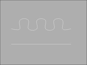
|
To smooth a curve: 1. | With a curve selected, choose Edit Curves > Modify Curves and click the option box next to Smooth (Figure 7.37).
Figure 7.37. Select Smooth from the Edit Curves > Modify Curves menu. 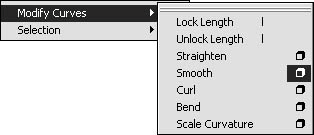
The Smooth Curves Options dialog box opens.
| 2. | Set the Smooth Factor to 10 (Figure 7.38).
Figure 7.38. Set the Smooth Factor to 10. 
| 3. | Click Apply.
The jagged curve becomes smoother (Figure 7.39).
Figure 7.39. The top curve is jagged before applying the Smooth function. The bottom curve is the result. 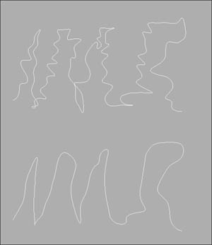
|
To curl a curve: 1. | With a curve selected, choose Edit Curves and click the option box next to Rebuild Curves (Figure 7.40).
Figure 7.40. Select the option for Edit Curves > Rebuild Curve. 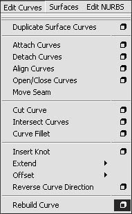
The Rebuild Curves Options dialog box opens.
| 2. | Set the Number of Spans to 25 (Figure 7.41).
Figure 7.41. Set the Number of Spans to 25. 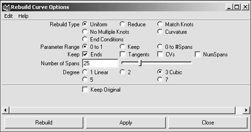
| 3. | Click Rebuild.
The effect of curl will be more apparent if your curve has many CVs in it.
| 4. | Choose Edit Curves > Modify Curves and click the option box next to Curl (Figure 7.42).
Figure 7.42. Select Edit Curves > Modify Curves > Curl. 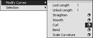
The Curl Curves Options dialog box opens.
| 5. | Set the Curl Amount to 2 and the Curl Frequency to 1 (Figure 7.43).
Figure 7.43. Set the options for Curl Curves. 
| 6. | Click Apply. The curve becomes a spiral (Figure 7.44).
Figure 7.44. The top curve is straight before being curled. The bottom curve is the result. 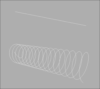
|
To bend a curve: 1. | With a curve selected, choose Edit Curves > Modify Curves and click the option box next to Bend (Figure 7.45).
Figure 7.45. Select Edit Curves > Modify Curves > Bend. 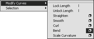
The Bend Curves Options dialog box opens.
| 2. | Set the Bend Amount to .15 (Figure 7.46).
Figure 7.46. Set the options for Bend Curves. 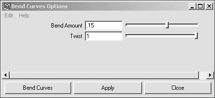
| 3. | Click Apply.
The curve becomes more like a circle (Figure 7.47).
Figure 7.47. The top curve is straight before being bent. The bottom curve is the result. 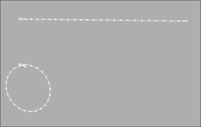
|
To scale curvature: 1. | With a curve selected, choose Edit Curves > Modify Curves and click the option box next to Scale Curvature (Figure 7.48).
Figure 7.48. Select from the Edit Curves > Modify Curves > Scale Curvature. 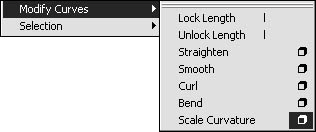
The Scale Curvature Options dialog box opens.
| 2. | Set the Scale Factor to .5 and the Max Curvature to 1 (Figure 7.49).
Figure 7.49. Set the options for Scale Curvature. 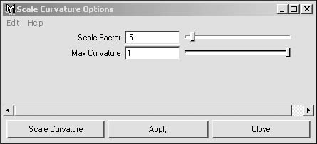
| 3. | Click Apply. The curve expands (Figure 7.50).
Figure 7.50. The top curve is tighter before applying Scale Curvature. The bottom curve is the result. 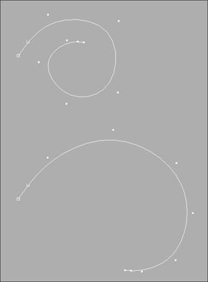
|
 Tip Tip
You can also apply the Straighten, Smooth, Curl, Bend, and Scale Curvature effects to selected CVs instead of to the entire curve.
|


 Tip
Tip


