Chapter 10: Contrasting Deployments
|
| < Day Day Up > |
|
Like any new technology, Wi-Fi can solve some problems, but create other challenges. Providing appropriate network coverage can be the most difficult issue faced when designing a wireless local area network (WLAN). This chapter, hopefully, will give the reader valuable insight and practical knowledge of different aspects of wireless networking technology, some of the general issues that each Wi-Fi flavor presents, and awareness of specific problems that may arise during implementation of the various Wi-Fi technologies. We will begin with a couple of practical deployment scenarios.
Practical Deployments
Let's explore practical deployment scenarios for both 802.1 la (current and optimized) and 802.11b, including three-cell and eight-cell configurations.
| Note | I want to thank CMP Media LLP and Jung Yee and Hossain Pezeshki-Esfahani, the authors of "Understanding Wireless LAN Performance Trade-Offs," published in the November 2002 issue of Communication Systems Design magazine, as the following text and metrics relies heavily upon that article. |
To cover areas greater than that provided by a single access point (AP), network designers may deploy multiple APs in a hexagonal cellular arrangement. Each cell has one AP at its center, so that end-users can access the WLAN from anywhere in a cell. To maintain performance levels and effective data rates, the bit error rate (BER) should not exceed 10e-5 anywhere in the network.
To make the problem tractable, assume at any given time that there is only one station, or wireless computing device, transmitting in each cell. The collision avoidance and back-off behavior of the 802.11 Media Access Controller (MAC) make this a good assumption in distributed-coordination function mode, while in the point-coordination function mode the assumption is nearly literally valid. Owing to the high degree of asymmetry of traffic flow, you should also assume that the only potentially jamming stations are the APs in other cells.
From the spectral masks and channel allocations described by the IEEE, you can infer that the fraction of spectral leakage (l) from one adjacent channel is 4.282853E-3 (-23.68 dB) for an 802.1 la network, and 3.63273E-4 (-34.40 dB) for an 802.11b network.
As you should now understand, the 802.11b specification, in its current form, has three channels available for use. This number is important because it dictates how 802.11b access points are placed to cover wireless geography into areas called cells. 802.11a, on the other hand, has eight channels, and therefore while each specification's radio broadcast patterns are roughly the same, programming cells are decidedly different between the two standards. And it can get really complicated when planning a network with dual-channel or hybrid 802.11a/b access points.
| Note | If you associate access points as cells, each cell has a broadcast pattern available for client hardware. The client hardware will associate with access points at a specific data rate that is a function of the quality and signal strength between the two devices. |
Three-cell Networks
Consider a network of three cells (Fig. 10.1). Since 802.11b affords only three frequency channels, one of the three cells (for example, Cell 3) experiences adjacent-channel interference (ACI) from the other two cells.
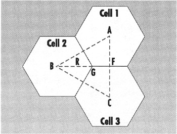
Figure 10.1: In an 802.11b network of three cells, one of the three cells (Cell 3) experiences adjacent-channel interference (ACI) from the other two cells because the 11b standard provides for only three frequency channels.
The greatest interference noise power (IN) is experienced by an end-user belonging to Cell 3 located at Point G in Fig. 10.1. Using Equation 6, the IN value at G is as shown in Equation 1.
| (1) | 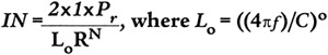 |
Similarly, the desired signal power is given by Equation 2.
| (2) |
The signal-to-interference noise ratio is therefore equal to SINR = (2f)-1, which is 31.39 dB. By comparing this number with Fig. 7.4's 802.11b numbers, one sees that all 802.11b data rates can be supported. The size of the network in Fig. 10.1 can be calculated by finding the radius of each hexagon. (This is a function of the Tx power and the minimum Rx sensitivity.) As mentioned previously, it is necessary to use a minimum Rx sensitivity of -70 dBm due to ACI. Note that a +15-dBm solution can cover 8844 square yards (7398 square meters) at 11 Mbps, while a +19-dBm model will offer better range (137 feet/42 meters as opposed to 101 feet/31 meters), and therefore a larger total area of coverage (16,349 square yards or 13,670 square meters).
The 802.11a standard has more channel flexibility. If a 54 Mbps transfer rate is desired, the WLAN designer can choose, for instance, channels 1, 5 and 8 for Cells 1, 2 and 3 to eliminate adjacent-channel interference. In this case, the APs in Cell 1 and Cell 3 can radiate at +23.01-dBm EIRP, while the AP in Cell 2 can radiate at +16.02-dBm EIRP. Consequently, Cells 1 and 3 each cover 1370 square yards (1146 square meters), while Cell 2 covers 525 square yards (439 square meters), with a total coverage of 3265 square yards (2730 square meters). Although this total coverage area is less than the 802.11b examples, the WLAN has a transfer rate capacity of 54 Mbps (and a throughput of about 31 Mbps).
Having calculated coverage dictated by the IEEE 802.11a standard, what can real-world WLANs deliver? With an optimized 802.1 la solution, designed to deliver 23 dBm, the coverage of a three-cell deployment with 54 Mbps will reach 3265 square yards (2730 square meters).
Alternatively, if a transfer rate of 12 Mbps is preferred (to reduce costs or the number of APs), then channels 5, 7 and 8 can be used for Cells 2, 3 and 1 respectively. This will result in ACI only between channels 7 and 8 and all APs can radiate +23.01 dBm. In this example, the interference noise power is as shown in Equation 3.
| (3) |
So the least SINR is f-1, or 23.68 dB. As a result, all but the two highest Orthogonal Frequency Division Multiplexing (OFDM) rates are accessible. Maintaining at least 12 Mbps requires a cell radius of 47.59 meters (congruent hexagons), so that the total area covered is now about 21,109 square yards (17,650 square meters).
Eight-cell networks
An eight-cell 802.11a network is depicted in Fig. 7.4. If all of the cells are congruent, then all of the APs must transmit at the same power level. This requires the maximum power of 40 milliwatts (+16.02 dBm) and, in this case, a computing device belonging to Cell 4, located at Vertex G, experiences the greatest interference.
The sources of interference are the two adjacent-channel interferers, one at 2R and the other at root 7R. Therefore, the least SINR experienced by any station throughout the network is given by Equation 4, or about 31.49 dB.
| (4) | 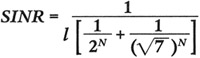 |
Comparing this number with the S/Ns for 802.11a in Fig. 7.4, we see that a data transfer rate of 54 Mbps is accessible throughout the WLAN. The total area covered in this configuration is 2490 square yards (2082 square meters).
An 802.11b WLAN can be used to cover a similar geometry as in the 802.1 la example above. The configuration outlined in Fig. 10.2 was carefully designed for an 802.11a application to mitigate co-channel and adjacent-channel interference, with the most interference being experienced by a computing device belonging to Cell 2 located at Vertex G. In comparison, a similar 802.11b configuration (Fig. 10.3) leads to a co-channel at 2R, a co-channel at root 7R, two adjacent channels at 2R, two adjacent channels at R, and one adjacent channel at root 7R. Therefore, the least SINR experienced by any device in the network is as shown in Equation 5, or about 7.45133 dB.
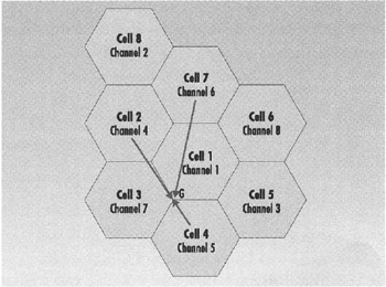
Figure 10.2: For an 8-cell 802.11a network, which allows for 54 Mbps operation, the greatest interference is experienced by a station belonging to Cell 4 located at Vertex G.
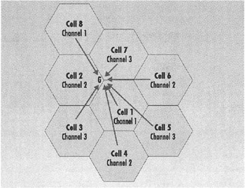
Figure 10.3: In an 8-cell 802.11b configuration, the least signal-to-noise ratio experienced by any station in the network is about 7.45133 dB, allowing for full 11 Mbps data transfer rate.
| (5) | 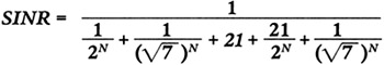 |
Comparing this with the S/Ns for 802.11b in Fig. 7.4, it is clear that a transfer rate of 11 Mbps is accessible throughout the 802.11b network. Note that a +15-dBm solution can cover 23,593 square yards (19,727 square meters) at 11 Mbps, while a +19-dBm model will offer coverage of 43,597 square yards (36,453 square meters).
As a side note, a concern for 802.11b/g systems is the proposed 22 Mbps Packet Binary Convolutional Coding (PBCC) extension (802.11g), which requires approximately 13.8 dB of S/N for a bit error rate less than 10e-5. In such a case, as Equation 6 shows, 802.11b networks requiring eight or more APs, 22 Mbps would not be accessible throughout the entire network.
| (6) |
Future 802.11a solutions that employ low-power, high-performance architectures may be able to transmit up to the maximum FCC limits. As a result, they will offer the range and data rate flexibility that will allow IT managers to tailor solutions to their specific applications and budgets, making an optimized 802.1 la system the perfect option.
|
| < Day Day Up > |
|
EAN: 2147483647
Pages: 273