26.2 The OSI Model
| |
The ISO has proposed a network model to provide guidelines for developing network protocols. This model is called Open Systems Interconnects, commonly known as OSI. This is a layered model where the functions of a network protocol are divided into seven layers . The OSI layered structure can be divided into two main parts . The lower four layers are related to data transfer functions taking place among participating hosts . Functions performed in these layers are error detection and correction, determination of route from source to destination, and utilization of underlying physical topology to transfer data in the form of electrical signals. The top three layers are related to the application- related matters such as data formats, opening/closing communication sessions, and user interaction.
OSI Layers
The OSI network model contains seven layers. The combination of these layers is known as the OSI protocol stack and is shown in Figure 26-1. In some literature, it is also known as OSI protocol suite. These layers are numbered from 1 to 7. The topmost layer (layer 7) is the application layer where most of the user interaction takes place. The bottommost layer is the physical layer where actual data transfer takes place from one point to another in the form of electrical signals.
Figure 26-1. The ISO-OSI protocol stack.
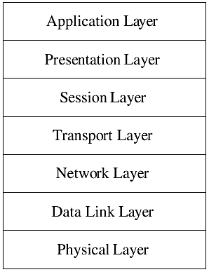
Each layer in the OSI protocol suite is responsible for certain operations. During the data transfer process, a layer interacts with its immediate upper layer and with the lower layers.
APPLICATION LAYER
The application layer provides user interface to the network. This layer consists of applications that initiate network communication. For example, you use the ftp command to transfer files from one host to another and the telnet or rlogin commands to log in to a remote system. These programs fall into the application layer and provide an interface where input from a user is taken and a network operation is performed according to that input.
Applications in the topmost layer usually act as a client or a server. A program started by a user is a client, and it interacts with a server application on the destination host. The destination host may be the same host or another host on the network. For example, when you start the ftp command, it interacts with the FTP server on a destination host.
PRESENTATION LAYER
Different computers on a network may use different data formats. For example, one machine may use the ASCII format while another may use EBCDIC. There may be some other machine-specific data formats. The presentation layer is responsible to format data according to a specific data format understandable to a machine.
SESSION LAYER
The session layer establishes, manages , and terminates a communication session. Applications use virtual connection points for communication between two systems on a network. These connection points are called network ports. By using these ports, it is possible to run multiple client and server applications simultaneously using one physical machine. During the session establishment process, the session layer opens a socket (which is a combination of a network port and the network address of a host) on the client side and connects it to the socket opened by the server application on a predefined port. The session layer then synchronizes and sequences the data transfer process during the data communication period. At the end of the data transfer process, the session layer closes the opened sockets on both sides, thus closing the session. On HP-UX, the defined ports for different applications can be found in the /etc/services file. For example, the port number of the telnet application is 23, while for FTP the port number is 21. If you are using your own application, you can use a port number that is not already in use by some other application.
TRANSPORT LAYER
The transport layer is used for reliable data transfer between a source and a destination. It provides end-to-end error detection and correction. If data are lost or contain errors, the transport layer on the receiving side requests the sending side to retransmit the data.
The data communication takes place in the form of data packets over the network. The transport layer also keeps a record of the sequence of these data packets. Sometimes, the data packets are received out of sequence. The transport layer is responsible for the correct sequencing of data packets before the data are transferred to the upper layer. The transport layer also drops duplicate packets in case more than one copy of the same data packet is received. Large amounts of data at the transport layer are divided into smaller data packets, which are reassembled at the receiving side.
NETWORK LAYER
The network layer is where unique logical network addresses, used to distinguish among hosts on a network, are assigned to hosts. It also provides routing information to transfer data within a LAN and across WANs. A route is a path from a source system to a destination system. The network layer is responsible for determining the best route between a source and destination. The network layer keeps the routing information updated, and a different route may be used during the same data transfer session if it becomes available. Determination of a route depends on many factors, such as the capacity of a communication path, traffic conditions along a path , number of intermediate points between the source and destination (hops), and so on.
A route falls into one of two categories. It is either a static route or a dynamic route. Static routes are predefined by a network administrator and are not dependent on network conditions. Dynamic routes, on the other hand, are calculated on the fly and change as network conditions change. The choice of a static or dynamic route depends on the availability, type, and number of interconnection paths. HP-UX supports both static and dynamic routing.
If the source and destination are not directly connected, the communication takes place with the help of intermediate machines known as routers. In this case, the data transfer process is completed in a number of hops, depending on the number of intermediate points. The network layer is responsible for point-to-point error detection and correction in such a case. Data packets at the network layer are called datagrams.
DATA LINK LAYER
The data link layer (DLL) is responsible for error-free data transfer over a physical medium (also known as hardware error correction). It is divided into two sublayers known as Logical Link Control (LLC) and Medium Access Control (MAC). LLC is used for communication with the network layer while MAC is used to access and control the physical medium. A physical addressing scheme is used at the MAC sublayer. These physical addresses are also called MAC addresses. Physical addresses are permanent addresses burnt into a network interface adapter. Data are divided into frames at the DLL and transferred from one system to another using the physical addresses. Special protocols are used to map physical (MAC) addresses to logical (network) addresses in a network.
PHYSICAL LAYER
The physical layer receives data frames from the DLL and converts these into electrical signals of 0s and 1s. It uses actual cable connections and signaling to transfer these data streams of 0s and 1s from source to destination.
Table 26-1 shows a listing of ISO-OSI network model layers and their responsibilities.
Table 26-1. The OSI Layers and Their Functionality
| Layer Number | Layer Name | Description |
|---|---|---|
| 7 | Application | Top-level applications that serve as user interfaces to the network. Data are generated in this layer on the sending side and received on the receiving side. |
| 6 | Presentation | Serves as data format converter if hosts participating in a network are using different data formats. |
| 5 | Session | Establishes and manages a communication session between two hosts. It terminates the session when the data transfer is complete. It uses port numbers , which are logical addresses used to establish data communication between client and server applications. |
| 4 | Transport | Used for reliable end-to-end data transfer, packet sequencing, retransmission, and acknowledgment of transmitted data. Data are divided into packets at this layer. |
| 3 | Network | Used for network addressing, routing, and point-to-point data error detection and recovery. Data packets are called datagrams at this layer. |
| 2 | Data link | Serves as an interface between the network layer and the physical layer. Physical or hardware (MAC) addresses are implemented at this layer. It controls access to the physical medium. Data packets at this layer are called frames. |
| 1 | Physical | Converts data frames received from the DLL to electrical signals and transmits these on the physical medium. |
How Data Transfer Takes Place Among Layers
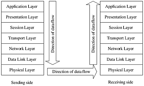
Data transfer starts when an application in the top layer initiates a network data transfer request. The data transfer process starts from the application layer, and the data to be transferred are handed over to the presentation layer. The presentation layer performs code conversion tasks , converts the data received from the application layer into the appropriate format and appends a presentation layer header to the data. This header contains information about changes made by the presentation layer and is used by the presentation layer on the receiving side to recover data. The presentation layer then hands over the data to the session layer. The session layer establishes a communication session with the destination host. It appends its header information to the data received from the presentation layer and hands it over to the transport layer. Each layer in this top-to-bottom approach adds its own header to the data and sends to its lower layer. These headers contain protocol information for the same layer (also called the peer layer) on the receiving side. When the data reach the physical layer, they are converted into a stream of 0s and 1s and transferred to the destination host.
On the receiving side, the physical layer receives data and sends them to the data link layer. Each layer on the receiving side takes off the header attached by the peer layer on the sending side and sends data to its upper layer. This process continues until the data reach an application in the application layer. This process is shown in Figure 26-2.
Figure 26-2. Data flow between two hosts in the OSI protocol stack.
PEER PROTOCOLS
Communication between peer layers, which are layers having the same layer number on both the source and destination hosts in the OSI protocol stack, is governed by certain rules and regulations called peer protocols. For example, the transport layers on the sending and receiving side of data are responsible for end-to-end data error detection and recovery process. Both layers follow certain rules to accomplish this job and to talk to each other in an orderly fashion. During the data transfer process, these two layers communicate with each other to acknowledge the accurate transfer of data (or otherwise ) using a peer protocol.
INTERFACES
Each layer in the OSI model communicates only with the layer immediately above or below it. The rules and regulations that govern data transfer between two adjacent layers in the OSI model are called interfaces.
Layered Network Model
The layered network model is designed to divide the complex task of network communication into different stages. User applications run in the topmost application layer. This is the layer where data originate for sending. A data transfer process starts at the application layer. On the sending side, each layer in a layered model communicates with the next lower level layer until the data reach the physical layer. Different operations take place during the data transfer from one layer to another. At the physical layer, the data are converted to electrical signals and are transferred to the destination process. On the receiving host, the data travel from the physical layer toward the topmost application layer, and reverse operations take place. Finally, the data are received by the application running on the destination host.
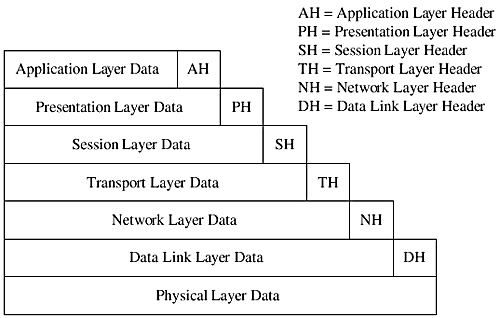
Peer protocols are used to convey information to peer layers between the source and destination hosts. The protocol information is transferred using layer headers appended to data at each layer. Thus, the amount of data transferred on the network is always larger than the actual data is. The additional data transfer the protocol information and may be called protocol overhead. The process of adding layer headers is shown in Figure 26-3. You can see that the physical layer data contain header information from all upper layers.
Figure 26-3. Addition of header information at each layer of OSI model.
| |
| |
| Top |
EAN: 2147483647
Pages: 390