Network Configuration
|
With all of the hardware, software, and concepts defined, implementation can proceed. Planners at CME developed at timeline to schedule interdependent tasks, such as site cutovers and equipment reallocations. The following configuration examples are not intended to be all-inclusive; many of the basic steps are omitted to focus on those germane to the Enterprise infrastructure and MetaFrame support.
Private WAN Sites (CORP Sales)
Private WAN Sales Offices (connected directly to CME Corp) all share common configurations. The CME-TNG configuration is similar, but with bandwidth management provided by the site router. Figures 17-3 and 17-4 depict the basic configuration for these sites.
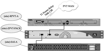
Figure 17-3: Typical Private WAN site network
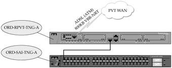
Figure 17-4: The CME-TNG site network
Router Configuration
The standard router configuration employs a single 768KB (CIR) frame relay PVC carried over a physical T1 local loop while the CME-TNG site uses an ATM VC over DSL. The two configurations are similar:
-
Basic settings for a Private WAN frame relay connection (ATL-RPVT-A)
-
LAN settings
interface FastEthernet0 description Atlanta LAN ip address 10.200.33.1 255.255.255.128 speed 100 full-duplex
-
WAN settings
interface Serial0/0 description T1 Circuit ID 99ABGG243117 no ip address encapsulation frame-relay IETF no fair-queue service-module t1 remote-alarm-enable frame-relay lmi-type cisco
-
Frame relay PVC (subinterface)
interface Serial0/0.16 point-to-point description Uplink To CME-RPVT-A bandwidth 768 ip address 10.2.0.22 255.255.255.252 frame-relay interface-dlci 16
-
Routing
router eigrp 109 no auto-summary no eigrp log-neighbor-changes network 10.0.2.20 0.0.0.3 network 10.101.33.0 0.0.0.255
-
-
Basic settings for a Private WAN ATM/DSL connection (ORD-RPVT-TNG-A)
-
LAN settings
interface FastEthernet0 description CME-TNG LAN ip address 10.200.32.1 255.255.255.128 speed 100 full-duplex service-policy input CITRIX-LAN
-
WAN settings
interface ATM0 description Uplink to CME-RPVT-A bandwidth 800 ip address 10.2.0.18 255.255.255.252 atm vc-per-vp 256 no atm ilmi-keepalive pvc 0/32 protocol ip 10.2.0.17 vbr-nrt 800 800 16 oam-pvc manage encapsulation aal5snap
-
Traffic management
dsl operating-mode auto service-policy output LLQ hold-queue 224 in
-
Bandwidth Management
The Private WAN site bandwidth management paradigm is the most simplistic: guarantee bandwidth for server-based computing and control other traffic.
Private WAN Sites (Frame Relay) Management of traffic flows across the Private WAN network is controlled by PacketShaper units at each end of each link. A typical site configuration, shown in Figure 17-5, accomplishes the following:
-
Guarantees essential throughput at high priority for video teleconferencing (VTC) sessions
-
Guarantees a minimum bandwidth to every Citrix session, with priority access to additional bandwidth. As individual applications are visible to the Packeteer, those that are known to require more initial bandwidth or that may induce user perceptions of slowness (for instance, the screen display does not keep up with keyboard input) can be given even more granular preferential treatment with regard to bandwidth.
-
A generic container for "Controlled Traffic" is created to constrain ill-behaved flows like HTTP to a reasonable amount of bandwidth. Within that container, certain applications have priority access to the constrained bandwidth. For example: FTP traffic to and from a Sales Office directly to the Internet is generally less important than HTTP from the same site.
-
A generic container for "Restricted Traffic" is created to control applications that are not considered "essential" to business activities but are not expressly prohibited. Unacceptable traffic (Gnutella) as discarded immediately.
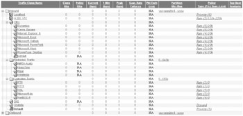
Figure 17-5: Typical private WAN Packeteer settings
The Private WAN Site (ATM/DSL) As mentioned previously, the ATM/DSL connection to the CME-TNG site does not require the expense of PacketShaper-based bandwidth management, but it still needs at least some controls to assure performance for Citrix sessions. The router (ORD-RPVT-TNG-A) is configured using Cisco's Modular Quality of Service (QoS) command-line interface (CLI) or MQC. The Traffic management command "service-policy output LLQ" shown in the basic configuration is based on the following parameters:
-
Define Citrix traffic by protocol (TCP port)
access-list 101 permit tcp any any eq 1494
-
Classify Citrix entering from the LAN into a logical group
class-map match-all ICA-LAN match access-group 101
-
Mark traffic classified as "ICA-LAN" (above) for preferential treatment using IP precedence
policy-map CITRIX-LAN class ICA-LAN set ip precedence 5 class class-default set ip precedence 0
-
Classify Citrix exiting to the WAN into a logical group
class-map match-all ICA-WAN match ip precedence 5 class class-default
-
Enforce preferential treatment (queuing) for up to 384KB of Citrix traffic
policy-map LLQ class ICA-WAN bandwidth 384 class class-default fair-queue
VPN WAN Sites (CME-WEST Sales and CME-EUR Sales)
CME-EUR and CME-MEX Sales Office sites rely on Internet connectivity for their VPN lifeline to CME Corp. As mentioned previously, the selection of a specific Internet router may not be an option due to host nation or ISP restrictions. The relatively low bandwidth also implies that the host nation ISP or circuit provider may not guarantee service in the form of an SLA. Bandwidth management is therefore not cost effective. To ensure a limited ability to cope with failures, each site will be equipped with a dial-up modem to allow remote terminal connectivity to the firewall in the event of a failure or problem (CME Corp staff will direct connection of the modem to the firewall console and reconfigure as required). Refer to Figure 17-6 for a graphic hardware layout of a typical site.
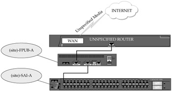
Figure 17-6: A typical VPN WAN site network
Firewall Configuration
The standard firewall/VPN configuration for all CME-WEST and CME-EUR sites establishes a VPN tunnel but disallows outbound access to the Internet by client PCs. The IPSec tunnel settings are a mirror image of the tunnel end-point on the ORD-FPUB-A (CME Corp) firewall. IP addresses used for the public segment are as assigned by the servicing ISP.
-
Basic settings for the HEW-FPUB-A (Athens) firewall:
nameif ethernet0 OUTSIDE security 0 interface ethernet0 100Full ip address OUTSIDE 88.88.88.88 255.255.255.240
-
Define logical groups of objects to simplify configuration
object-group network CME-Servers object-group description CME Servers and NMS Accessible to VPN Sites network-object 10.1.0.0 255.255.254.0 network-object 10.1.45.0 255.255.255.0 object-group network HEW-LAN object-group description CME-MEX LAN Subnets network-object 10.201.32.0 255.255.255.0
-
Define what local traffic is allowed to traverse the tunnels
access-list ORD-VPN permit ip object-group HEW-LAN object-group CME-Servers access-list VPN-NO-NAT permit object-group HEW-LAN object-group CME-Servers
-
Exempt site-to-site VPN traffic from the Network Address Translation (NAT) process
nat (inside) 0 access-list VPN-NO-NAT
-
Specify that IPSec is implicitly trusted
sysopt connection permit-ipsec
-
Specify that authentication of remote side identity is by IP address
isakmp identity address
-
Enable ISAKMP negotiation on the external interface
isakmp enable outside
-
Define IPSec polices
crypto ipsec transform-set cme-set esp-3des esp-sha-hmac crypto map cme-map 10 ipsec-isakmp crypto map cme-map 10 set transform-set cme-set crypto map cme-set 10 match address ORD-VPN crypto map cme-set 10 set peer 20.20.20.4 crypto map cme-set interface OUTSIDE
-
Define the Internet Key Exchange (IKE) policies
isakmp policy 10 authentication pre-share isakmp policy 10 group 2 isakmp policy 10 encryption 3des isakmp policy 10 hash sha
-
Specify the preshared key for each tunnel
isakmp key h&3jN(sv5Km.(s14 address 20.20.20.4 netmask 255.255.255.255
CME-EUR
Like the Sales Office sites, CME-EUR relies on Internet connectivity. Unlike the sales offices, CME-EUR has a higher throughput and greater demands, including printing and Domain replication. Because of the "commercial" grade Internet requirements, CME-EUR has an SLA for their Internet service. Bandwidth management is necessary to control the traffic traversing the VPN tunnel and ensure that the relatively high number of Citrix sessions do not become "starved" for bandwidth. CME-EUR has limited onsite IT staff and will not require immediate access to a modem connection for remote reconfiguration. The CME-EUR LAN switch is a consolidated distribution and access layer module, with only limited Layer 3 requirements (isolating the internal LAN segment from the uplink to the Packeteer and firewall). The CME-EUR configuration is detailed in Figure 17-7.
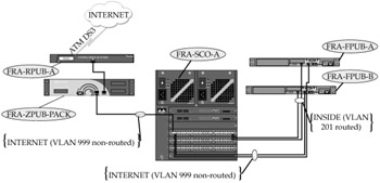
Figure 17-7: The CME-EUR network
Firewall Configuration
The firewall and VPN configuration for CME-EUR is similar to a Sales Office firewall configuration, but allows specific LAN hosts to access the Internet directly. The configuration example shown under CME-MEX is applicable to CME-EUR as well.
Bandwidth Management
Bandwidth management at CME-EUR is similar to a Private WAN site, but as almost all traffic is routed to CME Corp over the VPN tunnel, traffic must be policed before it enters the tunnel. Other modifications would include modified restrictions on traffic related to printing from the corporate site (NetBIOS IP, LPR), and less restrictions on Active Directory Domain replication traffic to the local domain controller.
CME-MEX
CME-MEX parallels CME-EUR, but with the additional restrictions imposed by the production environment. The manufacturing plant floor has little need for service beyond limited Citrix connectivity and no need for external Internet access through the corporate network. Again, bandwidth management is necessary to control client traffic behavior (allow reliable access to Citrix, police printing bandwidth consumption, allow management and administration staff Internet access, and restrict production subnets to corporate intranet access). Figure 17-8 shows the assembled network components.
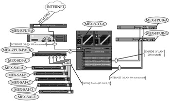
Figure 17-8: The CME-MEX Network
Firewall Configuration
CME-MEX firewall and VPN parameters (conceptually identical to CME-EUR) define the subnets that traverse the VPN tunnel but allow direct outbound access for a limited number of LAN hosts, specified by a fully qualified domain name (FQDN). As these sites are domain members of the CME Active Directory domain with a local domain controller/internal DNS server, the firewall can use the internal DNS and dynamic DNS registration of DHCP-addressed LAN hosts to identify hosts granted access by FQDN. Again, the VPN parameters are a mirror image of those at CME Corp.
-
Basic settings for MEX-FPUB-A
nameif ethernet0 OUTSIDE security 0 interface ethernet0 100Full ip address OUTSIDE 66.66.66.66 255.255.255.240
-
Define logical groups of objects to simplify configuration
object-group network CME-Servers object-group description CME Servers and NMS Accessible to VPN Sites network-object 10.1.0.0 255.255.254.0 network-object 10.1.45.0 255.255.255.0 object-group network MEX-LAN object-group description CME-MEX LAN Subnets network-object 10.201.4.0 255.255.252.0 object-group network INTERNET-ACCESS object-group description Local Hosts Allowed Internet Access network-object host mex-dc01.cme.com
-
Define what local traffic is allowed to traverse the tunnels
#notice it is a mirror of the one applied to the host PIX access-list ORD-VPN permit ip object-group MEX-LAN object-group CME-Servers access-list VPN-NO-NAT permit object-group MEX-LAN object-group CME-Servers
-
Exempt site-to-site VPN traffic from the Network Address Translation process
nat (INSIDE) 0 access-list VPN-NO-NAT nat (INSIDE) 1 object-group INTERNET-ACCESS global (OUTSIDE) 1 interface
-
Specify that IPSec is implicitly trusted
sysopt connection permit-ipsec
-
Specify that authentication of remote side identity is by IP address
isakmp identity address
-
Enable ISAKMP negotiation on the external interface
isakmp enable outside
-
Define IPSec policies
crypto ipsec transform-set cme-set esp-3des esp-sha-hmacv crypto map cme-map 10 ipsec-isakmp crypto map cme-map 10 set transform-set cme-set crypto map cme-set 10 match address ORD-VPN crypto map cme-set 10 set peer 20.20.20.4 crypto map cme-set interface OUTSIDE
-
Define Internet Key Exchange (IKE) policies
isakmp policy 10 authentication pre-share isakmp policy 10 group 2 isakmp policy 10 encryption 3des isakmp policy 10 hash sha
-
Specify the preshared key for each tunnel
isakmp key !h^Fsn)9,Oq$z@cU address 20.20.20.4 netmask 255.255.255.255
Bandwidth Management
CME-MEX is a somewhat larger mirror of CME-EUR. Basic bandwidth allocations are the same, but outbound Internet access is restricted by the PacketShaper based on approved host names (manually defined in the PacketShaper rules) as compared to the host's IP address as resolved by the internal DNS on the domain controller.
Core LAN Switch Configuration
The CME-MEX core switch (MEX-SCO-A) is the first switch that requires advanced Layer 3 routing functionality with its associated VLANs. By subnetting CME-MEX's address space, the designers simplified the process of restricting access to many services from the plant floor (production) hosts. The following partial configuration shows both the Layer 2 VLAN assignments and the Layer 3 routed interfaces. Note that VLAN 1 (default) is used only for interswitch VLAN control traffic, and VLAN 999 is passed through the switch at Layer 2 for visibility, but cannot be routed to any other VLAN. Each Layer 3 VLAN interface will have access lists defined to limit accessibility from VLAN-to-VLAN. Finally, the 802.1Q trunk to the plant floor switches only transports the PLANT VLAN and the SERVER VLAN (used for management).
vlan 2 name SERVERS vlan 3 name ADMIN vlan 4 name PLANT vlan 201 name INSIDE vlan 999 name OUTSIDE ! interface Vlan1 no ip address ! interface Vlan2 description CME-MEX Servers ip address 10.201.0.129 255.255.255.128 ! interface Vlan3 description CME-MEX ADMIN ip address 10.201.1.0 255.255.255.0 ip helper-address 10.201.0.100 ! interface Vlan4 description CME-MEX Plant Floor ip address 10.201.2.1 255.255.254.0 ! interface Vlan201 description CME-MEX firewall (MEX-FPUB-A INSIDE) ip address 10.201.0.14 255.255.254.240 ! interface Vlan999 no ip address ! interface GigabitEthernet4/1 description Uplink to PacketShaper 6500 Inside Interface switchport access vlan 999 switchport mode access spanning-tree portfast speed 100 duplex full ! interface GigabitEthernet4/2 description trunk to MEX-SDI-A Port Gi0/1 switchport trunk encapsulation dot1q switchport trunk native vlan 2 switchport trunk allowed vlan 1,2,4 switchport mode trunk ! interface GigabitEthernet4/3 description Connected to MEX-FPUB-A OUTSIDE switchport access vlan 999 switchport mode access spanning-tree portfast speed 100 duplex full ! interface GigabitEthernet4/4 description Connected to MEX-FPUB-B OUTSIDE switchport access vlan 999 switchport mode access spanning-tree portfast speed 100 duplex full ! interface GigabitEthernet4/47 description Connected to MEX-FPUB-A INSIDE switchport access vlan 201 switchport mode access spanning-tree portfast speed 100 duplex full ! interface GigabitEthernet4/47 description Connected to MEX-FPUB-B INSIDE switchport access vlan 201 switchport mode access spanning-tree portfast speed 100 duplex full ! interface GigabitEthernet5/1 description Connected to MEX-SDC01 switchport access vlan 2 switchport mode access spanning-tree portfast ! interface GigabitEthernet6/1 description ADMIN Client switchport access vlan 3 switchport mode access spanning-tree portfast
Access Switch Configuration (Plant Floor)
The individual access switches (MEX-SAI-A through E) on the plant floor are virtually identical. Client interfaces (fast Ethernet) are assigned to the "PLANT" VLAN, and the first gigabit Ethernet interface is configured as an 802.1Q trunk to the distribution switch (MEX-SDI-A). MEX-SDI-A interfaces are all configured as trunks, with the management address and default gateway (they are Layer 2 only) set for VLAN 2 (SERVERS).
vlan 2 name SERVERS vlan 4 name PLANT ! interface Vlan1 no ip address interface Vlan2 description CME-MEX Servers (Management VLAN ip address 10.201.0.151 255.255.255.128 ! interface GigabitEthernet0/1 description trunk to MEX-SDI-A Port Gi0/2 switchport trunk encapsulation dot1q switchport trunk native vlan 2 switchport trunk allowed vlan 1,2,4 switchport mode trunk ! interface FastEthernet0/1 description Plant Floor Access switchport access vlan 4 switchport mode access spanning-tree portfast ! ip default-gateway 10.201.0.129
CME-WEST
CME-WEST is the "backup" site for CME Corp. As shown in Figure 17-9, CME-WEST is actually an extensible subset of that infrastructure, including both Internet and Private WAN access.
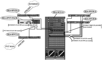
Figure 17-9: The CME-WEST network
Internet Router Configuration
The CME-WEST Internet access router (Cisco 7401) uses a single 1.5MB ATM Virtual Circuit (VC) carried over an ATM DS3 port for Internet access. The point-to-point subnet is assigned by the ISP, with CME-WEST's delegated address space routed by the ISP.
-
Basic settings for SEA-RPUB-A
-
WAN interface settings
interface ATM1/0 no ip address ip route-cache policy no ip mroute-cache atm scrambling cell-payload atm framing cbitplcp no atm ilmi-keepalive
-
ATM VC to the ISP
interface ATM1/0.11 point-to-point description Some-ISP 1.5MB Pipe ip address 100.100.100.102 255.255.255.252 pvc 4/32 ubr 1500 oam-pvc manage encapsulation aal5snap
-
LAN interface settings
interface fastethenet0/0 description CME-WEST router-to-firewall LAN segment ip address 20.20.22.1 255.255.255.192 speed 100 duplex full
-
Firewall Configuration
The CME-WEST firewall configuration is essentially a subset of the CME Corp configuration. It allows outbound access to the Internet for selected hosts, provides a single DMZ equivalent to CME Corp's SECURE-PUBLIC DMZ for a tertiary Secure Gateway and tertiary DNS. The VPN tunnels to the remote branches are not configured, but copies of the CME Corp configuration ensure they can be rapidly created.
Private WAN Router
The CME-WEST Private WAN Cisco 7401 is virtually identical to the Internet router, with the exception of the provisioned bandwidth and service type (vbr-nrt versus ubr). Additionally, the Private WAN router participates in the dynamic routing protocol (EIGRP) common to all Private WAN sites.
-
Basic settings for router SEA-RPVT-A
-
WAN interface settings
interface ATM1/0 no ip address ip route-cache policy no ip mroute-cache atm scrambling cell-payload atm framing cbitplcp no atm ilmi-keepalive
-
ATM VC settings
interface ATM1/0.100 point-to-point description Uplink to CME Corp ip address 10.2.0.254 255.255.255.252 pvc 1/10 vbrt-nrt 6000 6000 16 oam-pvc manage encapsulation aal5snap
-
LAN interface settings
interface gigabitethernet0/0 description LAN segment to CME-WEST Core (SEA-SCO-A) ip address 10.101.3.254 255.255.255.248
-
Routing
router eigrp 109 no auto-summary no eigrp log-neighbor-changes network 10.101.0.0 0.0.3.255 network 10.2.0.254 0.0.0.3
-
Bandwidth Management
The PacketShaper at CME-WEST does dual-duty through the added LEM. One segment manages the 6MB connection to CME Corp while the other monitors the Internet connection. Rules for traffic management in each segment are equivalent to rules in the stand-alone counterparts at CME Corp. No IPSec rules are established for VPN termination, but should the need arise, configuration settings for the CME Corp Internet PacketShaper could be modified and imported quickly.
Core LAN Switch Configuration
The CME-WEST LAN Core is somewhat underutilized on a day-to-day basis, but the over-build is necessary to position the switch as a backup for CME Corp. The switch's Layer 3 configuration is similar to CME-MEX with VLANs defined to isolate clients from the subset of servers that are homed at CME-WEST. CME-WEST has substantially more active servers than other regional offices, including redundant domain controllers, online backup servers for network and security management, a backup Citrix server that is part of the CME Corp farm, and an array of repository and backup servers used to store images and data that are replicated from CME Corp.
A significant portion of the core switch's capacity is "preconfigured" to support drop-in LAN access switches that would be purchased and deployed as part of a disaster recovery effort. Again, configurations (including server configurations) for critical systems at CME Corp are "backed up" at CME-WEST. CME-WEST will reuse CME Corp's IP addresses and identities by re-creating the same VLANs for reconstituted servers.
CME Corp
The CME Corp infrastructure is intended to meet design objectives (fast, redundant, hierarchical, fault-tolerant, and so forth) now and in the foreseeable future. In many cases, subsystem design components for the case study, including supporting network and security management elements, are beyond what many corporate networks employ today. Conversely, many of those same networks would be redesigned and reengineered for greater capacity and survivability if the performance warranted the effort and expense. When looking at the aggregate cost of leading edge hardware technologies, compare them to the cost of industry-leading ERP software packages and server systems—typically, infrastructure cost is a fraction of the major business application package, and the application package is considered so vital that "we lose money" when the system is down. The underlying network must be at least as reliable as the application software: based on the designer's efforts, CME's Enterprise SBC network should be up to the task.
Internet Access Module
The CME Corp high-bandwidth Internet access module consists of the Cisco 7401 routers and associated switch ports on the ORD-SDMZ-A switch. The routers operate using EBGP as a routing protocol against two upstream ISPs, and are responsible for announcing CME's primary Internet-routable subnet into the Internet routing tables. Internally, the outers use OSPF and static routes to receive routing information (routes must be learned from an IGP before being injected into the BGP process). The combination of OSPF, BGP, and redundant routers virtually eliminates the need to implement more troublesome techniques like Hot Standby Routing Protocol (HSRP) or Virtual Router Redundancy Protocol (VRRP) to ensure any combination of routes and equipment can carry critical traffic. As an added advantage, the Internet gateway routers will also maintain a full copy of the Internet routing tables for instant access.
Internet Routers Each Internet router terminates a single 15MB ATM virtual circuit carried over a DS3 local loop. Point-to-Point subnets for each upstream ISP are provided by the ISP, and the routers run BGP, with restrictions to prevent cross-routing of ISP traffic through CME Corp. Router configurations are similar to the CME-WEST Internet router (ATM ubr service).
Firewall Configuration The CME Corp firewall is typical of an enterprise-class firewall. It, like the regional site firewalls at CME-EUR, CME-MEX, and CME-WEST, maintains session state tracking, resulting in stateful failover to the redundant unit. Unfortunately, stateful failover cannot support IPSec tunnels since the encryption process is dynamically negotiated—all IPSec tunnels will temporarily drop during a failover. The CME Corp firewall set (ORD-FPUB-A & B) manages multiple DMZs based on the original corporate security model. Each DMZ is assigned a progressively higher (more secure) security level, with normal ingress and egress rules applied. As a footnote, isolation of the second "public" DNS in a more secure DMZ serves two purposes. First, the more secure server can be the "master" for replicating zone updates. Second, the server in the PUBLIC DMZ coexists with corporate web servers (public targets). A malicious attack on, and compromise of, a web server could expose the DNS server to a direct attack from within the same DMZ. The DNS server in the SECURE-PUBLIC DMZ shares the DMZ with servers that only allow HTTPS (SSL) traffic and are easier to secure. The ACCESS DMZ is intended to terminate inbound connections from known, unencrypted but authenticated sources (RAS, Wireless, and others), and apply inspection rules to these traffic flows. The SECURE-ACCESS DMZ is only for termination of traffic that is both encrypted during transport (with strong encryption), and authenticated (read here—VPN clients). Access lists for the CME Corp PIX are built much like lists for all other sites, but are far more complex due to the many traffic flows that must be allowed through the firewall. Even traffic originating in a "secure" segment like the SECURE-PUBLIC DMZ must be filtered by firewall rules and exposed to IDS monitoring before being allowed inside the firewall. The following subset of the firewall configuration provides the basic settings for VPN tunnels, address translation, and filtering rules.
-
Basic settings, including failover parameters
nameif gb-ethernet0 OUTSIDE security 0 nameif gb-ethernet1 INSIDE security 100 nameif ethernet0 PUBLIC security 20 nameif ethernet1 SECURE-PUBLIC security 40 nameif ethernet2 ACCESS security 60 nameif ethernet3 FAILOVER security 99 nameif ethernet4 intf4 security 0 nameif ethernet5 SECURE-ACCESS security 80 interface gb-ethernet0 1000Full interface gb-ethernet1 1000Full interface ethernet0 100Full interface ethernet1 100Full interface ethernet2 100Full interface ethernet3 100Full interface ethernet4 100Full shutdown interface ethernet5 100Full ip address OUTSIDE 20.20.20.4 255.255.255.0 ip address INSIDE 10.254.10.1 255.255.255.248 ip address PUBLIC 10.254.0.1 255.255.255.0 ip address SECURE-PUBLIC 10.254.1.1 255.255.255.0 ip address ACCESS 10.254.4.1 255.255.255.248 ip address intf4 127.0.0.1 255.255.255.255 ip address FAILOVER 1.1.1.1 255.255.255.252 ip address SECURE-ACCESS 10.254.8.1 255.255.255.248 failover ip address OUTSIDE 20.20.20.5 255.255.255.0 failover ip address INSIDE 10.254.10.2 255.255.255.248 failover ip address PUBLIC 10.254.0.2 255.255.255.0 failover ip address SECURE-PUBLIC 10.254.1.2 255.255.255.0 failover ip address ACCESS 10.254.4.2 255.255.255.248 failover ip address FAILOVER 1.1.1.2 255.255.255.252 failover ip address SECURE-ACCESS 10.254.8.2 255.255.255.248 failover link FAILOVER failover lan interface FAILOVER failover lan enable
-
Enable OSPF routing processes; public routes are redistributed to the private process
router ospf 999 network 20.20.20.0 255.255.255.0 area 0 router ospf 1 network 10.254.0.0 255.255.255.0 area 20 network 10.254.1.0 255.255.255.0 area 40 network 10.254.4.0 255.255.255.248 area 60 network 10.254.8.0 255.255.255.248 area 80 network 10.254.10.0 255.255.255.248 area 100 redistribute ospf 999
-
Define logical groups of objects to simplify configuration
object-group network CME-Servers object-group description CME Servers and NMS Accessible to VPN Sites network-object 10.1.0.0 255.255.254.0 network-object 10.1.45.0 255.255.255.0 object-group network VPN-Sites object-group description LAN Subnets of Remote Sites group-object FRA-LAN group-object MEX-LAN group-object HEW-LAN group-object AKL-LAN object-group network FRA-LAN object-group description CME-EUR LAN Subnets network-object 10.201.0.0 255.255.252.0 object-group network MEX-LAN object-group description CME-MEX LAN Subnets network-object 10.201.4.0 255.255.252.0 object-group network HEW-LAN object-group description Athens LAN Subnets network-object 10.201.32.0 255.255.255.0 object-group network AKL-LAN object-group description Auckland LAN Subnets network-object 10.201.33.0 255.255.255.0 object-group network CME-ENG object-group description Engineering LAN Subnets network-object 10.1.41.0 255.255.255.0 network-object 10.1.42.0 255.255.255.0 network-object 10.1.43.0 255.255.255.0
-
Define what local traffic is allowed to traverse the tunnels to each site
access-list MEX-VPN permit ip object-group CME-Servers object-group FRA-LAN access-list FRA-VPN permit ip object-group CME-Servers object-group MEX-LAN access-list HEW-VPN permit ip object-group CME-Servers object-group HEW-LAN access-list AKL-VPN permit ip object-group CME-Servers object-group AKL-LAN
-
Exempt site-to-site VPN traffic from the Network Address Translation (NAT) process
access-list VPN-NO-NAT permit ip object-group CME-Servers object-group VPN-Sites
-
Define address translation rules for selected traffic
nat (inside) 0 access-list VPN-NO-NAT nat (inside) 1 object-group CME-Servers nat (inside) 2 object-group CME-ENG global (outside) 1 20.20.20.192 netmask 255.255.255.255 global (outside) 2 20.20.20.193 netmask 255.255.255.255 static (inside,outside) 20.20.20.100 10.254.0.100 netmask 255.255.255.255 0 0 static (inside,outside) 20.20.20.101 10.254.1.101 netmask 255.255.255.255 0 0 static (inside,outside) 20.20.20.110 10.254.0.110 netmask 255.255.255.255 0 0 static (inside,outside) 20.20.20.111 10.254.1.111 netmask 255.255.255.255 0 0 static (inside,outside) 20.20.20.121 10.254.1.121 netmask 255.255.255.255 0 0
-
Specify traffic that is allowed to originate an inbound connection to web servers, secure gateway servers, DNS servers, and mail relay servers
access-list OUTIDE-IN permit tcp any host 20.20.20.100 eq http access-list OUTIDE-IN permit tcp any host 20.20.20.101 eq http access-list OUTIDE-IN permit tcp any host 20.20.20.100 eq 443 access-list OUTIDE-IN permit tcp any host 20.20.20.100 eq 443 access-list OUTIDE-IN permit udp any host 20.20.20.110 eq domain access-list OUTIDE-IN permit udp any host 20.20.20.111 eq domain access-list OUTIDE-IN permit tcp any host 20.20.20.121 eq smtp access-group OUTSIDE-IN in interface OUTSIDE
-
Specify that IPSec is implicitly trusted
sysopt connection permit-ipsec
-
Specify that authentication of remote side identity is by IP address
isakmp identity address
-
Enable ISAKMP negotiation on the external interface
isakmp enable outside
-
Define IPSec policies
crypto ipsec transform-set cme-set esp-3des esp-sha-hmac crypto map cme-map 10 ipsec-isakmp crypto map cme-map 10 set transform-set cme-set crypto map cme-set 10 match address MEX-VPN crypto map cme-set 10 set peer 66.66.66.66 crypto map cme-map 11 ipsec-isakmp crypto map cme-map 11 set transform-set cme-set crypto map cme-set 11 match address FRA-VPN crypto map cme-set 11 set peer 77.77.77.77 crypto map cme-map 21 ipsec-isakmp crypto map cme-map 21 set transform-set cme-set crypto map cme-set 21 match address HEW-VPN crypto map cme-set 21 set peer 88.88.88.88 crypto map cme-map 22 ipsec-isakmp crypto map cme-map 22 set transform-set cme-set crypto map cme-set 22 match address AKL-VPN crypto map cme-set 22 set peer 99.99.99.99
-
Define IKE policies
isakmp policy 10 authentication pre-share isakmp policy 10 group 2 isakmp policy 10 encryption 3des isakmp policy 10 hash sha
-
Specify the per-site preshared keys
isakmp key !h^Fsn)9,Oq$z@cU address 66.66.66.66 netmask 255.255.255.255 isakmp key $7nA0;*45Fzq!@zQ address 77.77.77.77 netmask 255.255.255.255 isakmp key h&3jN(sv5Km.(s14 address 88.88.88.88 netmask 255.255.255.255 isakmp key @n8Ao,^674n*3bFc address 99.99.99.99 netmask 255.255.255.255
VPN (Client VPN) The VPN termination for roaming clients is provided by the Cisco 3030 VPN Concentrator (redundant). Routing is a combination of static and OSPF to allow external routes to be propagated to the Internet router and PIX firewall. Individual client settings vary based on their role in the CME corporate environment—some are authenticated by the Windows 2000 Active Directory domain, some by internal accounts on the VPN concentrator, and some by RADIUS. Tunnel settings also vary, with most users locked in to "tunnel everything" for security reasons. Most tunnels use preshared keys, but the VPN concentrator is the "test-bed" for implementing certificate-based keying for future use on site-to-site PIC VPN tunnels.
Bandwidth Management Internet bandwidth at CME Corp cannot be "shaped" in the same way internal WAN sites can, but as a minimum, certain traffic types must be protected. Figure 17-10 shows
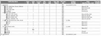
Figure 17-10: CME Corp Internet Packeteer settings
-
Traffic to and from the MetaFrame Secure Gateway, MSAM Access for supplier's, and public access to CME's public web presence are given preferential treatment over most inbound/outbound traffic flows.
-
IPSec, with known tunnel endpoints defined by source and destination address, is guaranteed a minimum amount of bandwidth with preferential access to additional bandwidth up to the Internet access bandwidth of the remote site (after all, the Citrix traffic from the sites is inside the IPSec packets).
-
Normal web browsing from the internal network is held as routine traffic, while web traffic sessions originated from the MetaFrame server farm are given slightly better treatment. If users see poor performance when browsing the web from Citrix, they may try to circumvent the system to cruise the web.
DMZ Distribution Switch (6509) Configuration The DMZ distribution switch (Catalyst 6509) configuration is complex. It employs a combination of routed (Layer 3 interface) and non-routed (Layer 2 only) segments to isolate traffic flows, expose all segments to the Intrusion Detection Module (IDS), and allow management platform visibility of traffic statistics. Additionally, isolated routed subnets are created by the Content Services Module to allow it to load-balance IP traffic (HTTP and DNS) across multiple DNS and web servers. Although detailed configurations are beyond the scope of this chapter, fundamental Layer 2 and Layer 3 configurations echo those of other corporate switches with several notable exceptions:
-
The switch runs multiple routing protocols such as
-
OSPF for route distribution with the PIX firewall internal interface, VPN concentrator internal interface, and the ACCESS-DMZ distribution switch (ORD-SDE-A), and RAS appliance (PortMaster)
-
EIGRP for route distribution with the CME Corp core switches (ORD-SCO-A and B)
-
Routing information is cross-distributed from OSPF to EIGRP and vice-versa
-
-
Several of the isolated VLANs (isolated from the main routing processes) are visible to the Content Services Module to facilitate load-balancing of web traffic to appropriate servers.
Figure 17-11 shows the combined Internet access layer, Security and VPN modules, DMZ distribution switch, and peripheral equipment.
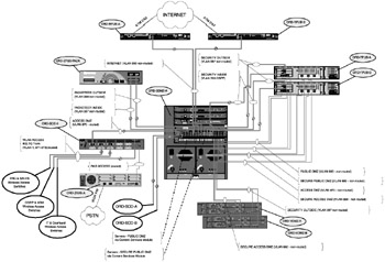
Figure 17-11: CME Corp Internet, Security Perimeter, and VPN/firewall configuration
ACCESS-DMZ Switch Configuration A secondary distribution switch (Cisco 3550-12G) (ORD-SDE-A) is used between the PIX firewall ACCESS DMZ interface and the separate access segments or wireless LAN (WLAN) and dial-up Remote Access Services (RAS). The 3550 enforces intersegment routing restrictions to limit the ability of wireless and RAS users to communicate directly, provides a first line of defense for the firewall against RAS or WLAN sources Denial of Service attempts, and aggregates the multiple VLAN/WLAN segments for the wireless network. Finally, to avoid exposing critical equipment and servers, the Catalyst 3550 provides DHCP server services to the WLAN segments. The switch runs OSPF on the uplink to the primary DMZ distribution switch (ORD-SDMZ-A) and on the downlink to the PortMaster. The routes to the connected Layer 3 interfaces for the wireless segments are announced up-stream, but blocked on all other interfaces by distribution lists and "passive interface" settings. The PortMaster does not need a route to the WLAN, and the WLAN devices are Layer 2 only.
The Private WAN Module
The Private WAN distribution module consists of the Cisco router, distribution aggregation switch, PacketShaper, and an IDS appliance to preinspect traffic arriving from the sites. Figure 17-12 depicts the operational configuration.
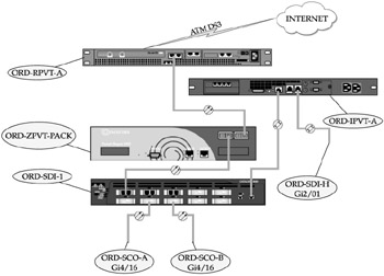
Figure 17-12: The Private WAN Distribution module
The Private WAN Router The Cisco 7401 router is configured to use a 1000Base SX LAN interface and an ATM-DS3 WAN interface. Configuration for the routing protocol (EIGRP) is similar to the Private WAN site routers, except that it has a much larger scope of assigned subnets (10.0.2.0/24). Configuration of the ATM interface is similar to that of CME-WEST.
Bandwidth Management The PacketShaper 8500 defines unique shaping parameters for each remote Private WAN site based on the site's assigned LAN subnet range. By controlling bandwidth at the LAN edge, the traffic destined for the Internet is "prepoliced" to appropriate values and no per-site settings are required on the Internet PacketShaper for these sites. The policies and partitions of remote sites are replicated at the main Private WAN PacketShaper. In Figure 17-13, note that the CME-TNG site (with bandwidth managed by MQC on the router) is classified as "ignore" (do not manage this traffic).
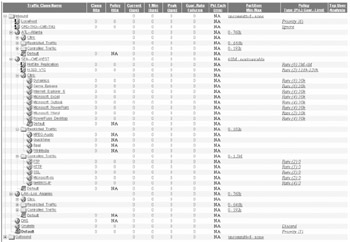
Figure 17-13: CME Corp Private WAN PacketShaper settings
The other notable feature is the CME-WEST "HotSite Replication" rule, a time-based rule that opens up the site-to-site bandwidth after-hours and guarantees best performance to intersite data replication to support disaster recovery.
CME-TNG bandwidth is not controlled by the PacketShaper. Instead, policing is managed by settings for the ATM Virtual Circuit (VC) on the router. To the PacketShaper, the subnets associated with CME-TNG are classified with an "Ignore" rule so that no shaping or policing of traffic flows is enabled. The same MQC parameters invoked at the CME-TNG router (ORD-RPVT-TNG-A) are used on the CME Corp's Private WAN router interface to CME-TNG. The following shows partial configurations for the CME Corp interface.
-
WAN setting (ATM subinterface and virtual circuit. Note that the output queuing policy is applied to the subinterface versus the main interface at CME-TNG.)
interface ATM1/0.32 point-to-point description 800KB ADSL to CME-TNG ip address 10.2.0.17 255.255.255.252 pvc 1/32 vbr-nrt 800 800 16 encapsulation aal5snap service-policy output CME-TNG
-
Identical traffic classification and marking parameters
class-map match-all ICA-LAN match access-group 101 class-map match-all ICA-WAN match ip precedence 5 ! policy-map CITRIX-LAN class ICA-LAN set ip precedence 5 class class-default set ip precedence 0 policy-map CME-TNG class ICA-WAN bandwidth 384 class class-default fair-queue ! access-list 101 permit tcp any any eq 1494 access-list 101 remark Identify ICA traffic by TCP Port#
The Campus LAN Access/Distribution Module
Access and distribution layer topology for the CME Corp campus was redesigned (based on the topology in Figure 10-2) to form a virtual "ring" (that is, in fact, a Layer 3 partial mesh) centered on the data center facility. By changing all links from individual buildings to the core to be both redundant and Layer 3 (Figure 17-14), the designers eliminated issues related to spanning tree in the campus network—spanning tree instances on each switch are only locally significant because of the Layer 3 (routed) boundary. Switch routing tables will always contain the next-best route to the core, ensuring immediate convergence in case of a link failure.
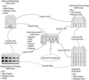
Figure 17-14: Campus LAN access/distribution topology
Typical LAN Access/Distribution Switch Configuration The campus building switches are only partially fault-tolerant (single supervisor module), but multi-homed at Layer 3 to ensure connectivity to the core. Figure 17-15 shows the physical connectivity.
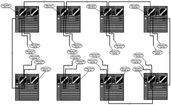
Figure 17-15: Campus LAN access/distribution (partial)
Building distribution switches in the "virtual ring" are all based on the same template: 10/100/1000 Ethernet connections for in-building hosts, with multiple fiber-optic gigabit uplinks to adjacent switches and the core switches for resiliency. Individual interfaces for switch-to-switch connectivity have no need for VLAN parameters, so they are locked in as Layer 3 routed interfaces only with the "no switchport" command.
Switch-to-switch connectivity for a typical LAN distribution switch, using ORD-SDI-C (ENG-C) as a model follows:
-
The local LAN segment
vlan 2 name ENG-C-Clients ! interface Vlan1 no ip address ! interface Vlan2 description ENG-C Clients ip address 10.1.43.1 255.255.255.0
-
Switch-to-switch (distribution-to-distribution)
interface GigabitEthernet1/1 description Link to ORD-SDI-B Port Gi1/2 no switchport ip address 10.2.1.138 255.255.255.252 interface GigabitEthernet1/2 description Link to ORD-SDI-D Port Gi1/1 no switchport ip address 10.2.1.141 255.255.255.252
-
Switch-to-switch (distribution-to-core)
interface GigabitEthernet2/1 description Uplink to ORD-SCO-A Port Gi4/3 no switchport ip address 10.2.1.42 255.255.255.252 ! interface GigabitEthernet2/2 description Uplink to ORD-SCO-AB Port Gi4/3 no switchport ip address 10.2.1.74 255.255.255.252
-
Routing
router eigrp 109 no auto-summary no eigrp log-neighbor-changes network 10.1.43.0 0.0.0.255 network 10.2.1.40 0.0.0.3 network 10.2.1.72 0.0.0.3 network 10.2.1.136 0.0.0.7
The WLAN Access Module
The WLAN Access Points (Cisco 1200 series) are configured as 802.1Q trunks on their internal (Ethernet) interfaces. VLAN 871 is used for management but is not "mapped" to an equivalent WLAN segment. VLAN 872 is mapped to the corporate WLAN on a unique non-broadcast System Security Identifier (SSID) that requires RADIUS (LEAP) authentication. By tying the WLAN segment to RADIUS, CME IT staff can force positive mutual authentication of clients, enforce session key rotation, and ensure only specifically authorized users are allowed WLAN access. VLAN 873 is mapped to a "public" WLAN that uses no encryption or authentication and assumes default SSID values (tsunami). The Layer 3 interface for VLAN 873 is filtered by multiple access lists designed to restrict WLAN clients from accessing CME Corp public servers (web servers) and the Internet. As a security measure, the Layer 3 interface on switch ORD-SDE-A is maintained in a "shutdown" state to prevent use of this segment without prior coordination. As a secondary check, access attempts (associations) are logged by the individual Access Points as an audit trail—the WLAN is "active," just not connected beyond the Access Point. Figure 17-16 shows the WLAN topology.
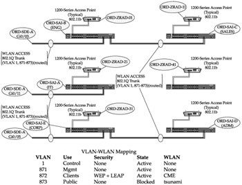
Figure 17-16: The Campus WLAN access/distribution topology
The Core Module
The dual Catalyst 6513 core (Figure 17-17) is linked by a 10GB Ethernet fiber link using single-mode fiber transceivers originally intended for far greater distance (optical attenuation is required), this allows the server farms and core switches to be physically separate in different areas of the data center without loss of throughput. Individual fiber links (Layer 3) to every campus distribution switch, the DMZ switch, and the Private WAN distribution module ensure that no single failure, or even the failure of an entire core switch, can disrupt operations. (Remember, the Citrix farm and critical servers are distributed redundantly across both switches.) Failure of the core-to-core fiber link imposes little, if any, performance penalty as the multiple links through the distribution switches will dynamically reroute and load-balance (via EIGRP) the traffic.
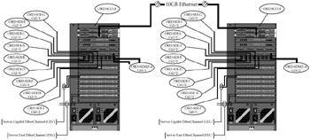
Figure 17-17: The dual core module
The Core Switch Configuration A partial configuration from switch ORD-SCO-A illustrates the connectivity to the distribution layer and adjacent core switch. Key elements of the configuration for servers are reflected in module 9 ports 1 and 2 (Gigabit EtherChannel (GEC)), and module 12 ports 1 and 2 (Fast EtherChannel (FEC)).
-
The local LAN segment for the server farm
vlan 2 name ServerFarm-A ! interface Vlan1 no ip address ! interface Vlan2 description ServerFarm-A Hosts ip address 10.1.0.1 255.255.255.0
-
Switch-to-switch (core-to-core)
interface TenGigabitEthernet 3/0 description Backbone link to ORD-SCO-B 3/0 no switchport ip address 10.2.1.1 255.255.255.252
-
Switch-to-switch (ORD-SCO-A-to-distribution)
interface GigabitEthernet5/1 description Link to ORD-SDI-A Port Gi2/1 no switchport ip address 10.2.1.33 255.255.255.252 interface GigabitEthernet5/2 description Link to ORD-SDI-B Port Gi2/1 no switchport ip address 10.2.1.37 255.255.255.252 interface GigabitEthernet5/3 description Link to ORD-SDI-C Port Gi2/1 no switchport ip address 10.2.1.41 255.255.255.252 interface GigabitEthernet5/4 description Link to ORD-SDI-D Port Gi2/1 no switchport ip address 10.2.1.45 255.255.255.252 interface GigabitEthernet5/5 description Link to ORD-SDI-E Port Gi2/1 no switchport ip address 10.2.1.49 255.255.255.252 interface GigabitEthernet5/6 description Link to ORD-SDI-F Port Gi2/1 no switchport ip address 10.2.1.53 255.255.255.252 interface GigabitEthernet5/7 description Link to ORD-SDI-G Port Gi2/1 no switchport ip address 10.2.1.57 255.255.255.252 interface GigabitEthernet5/8 description Link to ORD-SDI-H Port Gi2/1 no switchport ip address 10.2.1.61 255.255.255.252 interface GigabitEthernet5/16 description Link to ORD-SDMZ-A Port Gi5/1 no switchport ip address 10.2.1.5 255.255.255.252 interface GigabitEthernet6/1 description Link to ORD-SDI-I Port Gi0/3 no switchport ip address 10.2.0.1 255.255.255.252
-
GEC for the file server
interface Port-channel1 no ip address switchport access vlan 2 switchport mode access interface GigabitEthernet9/1 description GEC-1 Primary Port (ORD-SFS-01 NIC 0) switchport access vlan 2 switchport mode access channel-group 1 mode desirable spanning-tree portfast interface GigabitEthernet9/2 description GEC-1 Secondary Port (ORD-SFS-01 NIC 1) switchport access vlan 2 switchport mode access channel-group 1 mode desirable spanning-tree portfast
-
FEC for the RADIUS server
interface Port-channel101 no ip address switchport access vlan 2 switchport mode access interface GigabitEthernet9/1 description FEC-1 Primary Port (ORD-SSE-01 NIC 0) switchport access vlan 2 switchport mode access channel-group 101 mode desirable spanning-tree portfast speed 100 duplex full interface GigabitEthernet9/2 description FEC-1 Secondary Port (ORD-SSE-01 NIC 1) switchport access vlan 2 switchport mode access channel-group 101 mode desirable spanning-tree portfast speed 100 duplex full
-
Routing
router eigrp 109 no auto-summary no eigrp log-neighbor-changes network 10.1.0.0 0.0.0.255 network 10.2.1.0 0.0.0.255
Server-Side Network Settings
Network interoperability requires correct (matching) configurations between the server-side hardware (network interface card (NIC)) and the associated switch interface. Using Intel NIC hardware as an example, there are several critical settings that must be configured to ensure the best performance:
-
Speed
-
Set manually to 100 MBps for FastEthernet
-
Auto-negotiate with flow control allowed for GigabitEthernet
-
-
Duplex
-
Set manually to full-duplex for FastEthernet
-
Auto-negotiate for GigabitEthernet
-
-
Power management
-
Disabled (no low power during standby)
-
-
Load balancing
-
Use link aggregation (FEC or GEC)
-
Avoid adapter-based fault tolerance
-
Requires disabling spanning tree or using a hub (half-duplex)
-
Uses only one NIC at a time
-
-
Avoid switch-based fault tolerance
-
Requires spanning tree be enabled, and incurs the spanning tree listening-learning-forwarding transition delay (15 seconds) when failing over
-
Uses only one NIC at a time
-
-
Avoid adaptive load balancing
-
Only the primary NIC handles broadcast traffic
-
Only the primary receives traffic
-
Outbound NIC selection (by destination IP) is off-loaded to an operating system service
-
-
Creating an FEC/GEC EtherChannel (Layer 2 link aggregation) is the preferred method for increasing the aggregate bandwidth available to MetaFrame or other servers. By their nature, they are fault-tolerant and can run with only one member of the team, but with two or more members active, traffic is dynamically load-balanced across a virtual "fat pipe."
Basic configuration involves creating an EtherChannel "team," and then adding members. One member must be designated as "primary" and this MAC address will register as the address of the team. Figure 17-18 shows the teamed configuration and identifies the team MAC address and IP address.
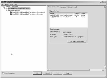
Figure 17-18: The FEC adapter team
Individual member adapters must be correctly configured independently for 100MB, full-duplex. The secondary adapter is shown in Figures 17-19 through 17-21. Note that it reports the MAC address of the team/primary adapter. Finally, Figure 17-21 shows the power management settings (enabled by default) that are inappropriate for a server and may cause flapping on an FEC team.
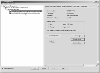
Figure 17-19: The FEC member adapter (general)
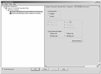
Figure 17-20: The FEC member adapter (link settings)
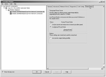
Figure 17-21: The FEC member adapter (power management)
|
EAN: 2147483647
Pages: 158