Section 4.1. Basic Properties of Antennas
|
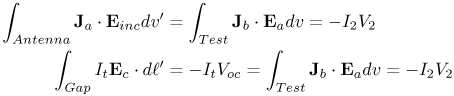
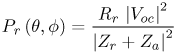
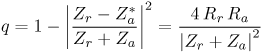
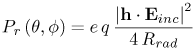
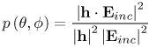
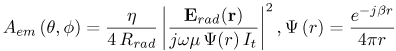
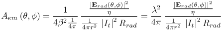
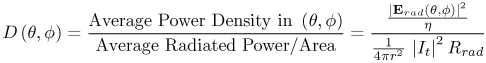
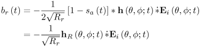
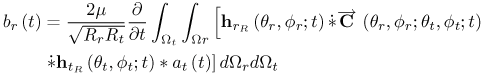
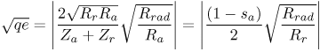
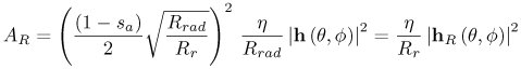
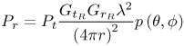
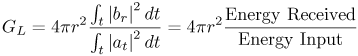
4.1. Basic Properties of AntennasThis section identifies the classic terms used to characterize antennas. We begin with a discussion of antenna effective length and the link equation based on reciprocity. Some extra coverage is provided for the use of reciprocity due to misuse of the term in communications. 4.1.1. Reciprocity and Antenna Effective LengthReciprocity is often incorrectly used by communications engineers to claim that the receive and transmit properties of an antenna are identical. The fundamental error in these arguments relates to neglecting a test-probe antenna used to measure the radiated electric field. To obtain the desired relationships, a bit more care is required. Three problems are needed to establish the reciprocity relationships required in the development of gain. First, we must establish a transmit problem (Figure 4.1a) to interact with the receive problem of interest (Figure 4.1c). We must establish an additional receive problem defining the incident field (Figure 4.1b). The I2 current of Figures 4.1(b) and (c) represents an infinitesimal dipole located at the same position as the measured radiated voltage, V2, in Figure 4.1(a). We may simply write the reciprocity theorem for any two problems as [2] Equation 4.3 where J and E represent current density and electric field intensity, respectively. Applying reciprocity to problems a and b, and also to problems a and c, we have Equation 4.4 Equating (I2 V2) in both equations we have Equation 4.5 The details now involve expanding this form for the open-circuit voltage and relating all of the terms to obtain the expressions for the link. We can write the incident field as a plane wave emanating from the Equation 4.6 where Ei contains all of the angular information and is perpendicular to the direction Equation 4.7 or Equation 4.8 where h is the effective length of the antenna given by Equation 4.9 The usual conjugation has not been used for h to be consistent with the transient use of effective length. The integral in the effective-length definition can be further reduced to the radiation terms of the antenna by noting that the radiated far field, Erad (r), is given by Equation 4.10 Substituting (4.10) into (4.9), we obtain Equation 4.11 to give the radiated electric field of an antenna as Equation 4.12 In the time domain, the form of (4.9) for the effective length with an input current of d (t) becomes Equation 4.13 The corresponding open-circuit voltage and radiated field are then Equation 4.14 Equation 4.15 where the compound operator, 4.1.2. Directivity, Gain, and Related DefinitionsIn the frequency domain, it is common to use antenna gain or area to represent the properties of the antenna rather than effective length. In this section, we relate the effective length to these factors. The frequency-domain received power of a link may be defined in terms of the incident power density, Saver, and effective area, Ar, by Equation 4.16 where the incident power density is given by |Ei|2 /h. To find the desired form of the effective area, we first consider the circuit representation of the antenna in Figure 4.2 given by the open-circuit voltage, Voc, the radiation resistance, Rrad, the loss resistance, Rloss, and the receiver impedance, Zr, along with the antenna reactance, Xa. For convenience, we represent the total antenna resistance as Equation 4.17 Figure 4.2. The Circuit Equivalent of the Antenna for Power Evaluation.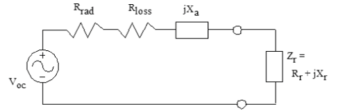 With this circuit definition, we may write the received power in terms of the RMS open circuit voltage as Equation 4.18 where Za = Ra + jXa. Because both the antenna loss and the impedance mismatch between the antenna and the receiver are included in the received power, Pr, we break out both the efficiency, e, and the mismatch loss factor, q. The mismatch loss factor, q, is defined as the ratio of the power delivered to the receiver compared to the power available from the antenna. This can be written in terms of the powerwave reflection coefficient [3] or directly in terms of the circuit quantities to obtain the mismatch factor Equation 4.19 Efficiency is defined as Equation 4.20 to obtain Equation 4.21 The effective area is obtained by inserting the definition of Voc as Equation 4.22 The polarization factor, p (q, f), of the antenna relates the alignment of effective length and the incident field as Equation 4.23 showing the importance of defining the dot product for polarization effects. The resultant received power becomes Equation 4.24 or Equation 4.25 The corresponding maximum effective area, sometimes also called the collecting aperture or effective radiating aperture, is Equation 4.26 where h is the characteristic impedance of space, typically given by 120p W. The realized effective area associates the efficiency and the mismatch with the area as Equation 4.27 The effective area is often related to the gain in a simple formula using the wavelength of the signal. To develop this relationship, we substitute for the effective length to obtain the maximum effective area in terms of the radiated field as Equation 4.28 Expanding and rearranging, we have Equation 4.29 where wm = bh and b = 2p/l. The directive gain of an antenna is defined as Equation 4.30 to give Equation 4.31 The received power can thus be written as Equation 4.32 with Sinc representing the incident power intensity (Poynting vector). The corresponding realized effective area of the antenna is Equation 4.33 for the direction (q, f). The polarization factor, p (q, f), has been left for separate inclusion because it represents an interaction between the antennas and is not a property of a single antenna. The realized gain, GR, includes both the efficiency and mismatch loss of the antenna. If the polarization match to a given incident field is included, the gain is denoted as the partial realized gain, gR [4]. Communications engineers commonly desire to specify certain terms separately, particularly polarization and mismatch, and also to restrict the evaluation to the main beam of the antenna. Thus, we summarize the maximum effective area in the main-beam direction without consideration of the polarization or mismatch as Equation 4.34 with D defining the directivity of the antenna. It is common practice to denote the angular maximums of the areas and gains without the angle designations as shown in (4.34). 4.1.3. A Link Model Using S-ParametersIf we wish to put the received-signal form in an S-parameter context, we need to evaluate the resultant voltage transferred to a reference load impedance, Zo, or equivalently to the receiver, Zr. In this context, we have the power wave at the receiver (normalized load voltage) in the frequency domain as Equation 4.35 or in the time domain as Equation 4.36 The quantity sa represents the reflection coefficient of the antenna and is given as (Za - Equation 4.37 In terms of the effective length, the received signal is given by Equation 4.38 where we define the realized effective length, hR, as Equation 4.39 Farr [5] defines the normalized impulse response of the antenna as hR normalized by The link between two line-of-sight (LOS) antennas is easily established with the definition of effective length. The incident field can be written in terms of a transmit effective length as Equation 4.40 or in the time domain as Equation 4.41 For an S-parameter form, we must convert the current to a power wave as well as provide for the mismatch to the transmitter impedance. Again, we find a form of the effective length given by Equation 4.42 or in terms of the realized effective length Equation 4.43 The quantity at (t) represents the square root of the instantaneous available power from the source. Combining terms, we have the received power wave as Equation 4.44 where the angles for the receive and transmit directions are simply the negative of each other. The LOS propagation loss is given by the 1/4pr term and the time delay of r/c. The frequency domain form of (4.44) is given by Equation 4.45 For a multipath propagation problem, the full context of the received signal is given by Equation 4.46 where Equation 4.47 and characterize the channel by C (t), including both the channel properties and the polarization effects. In (4.27) we found that the realized effective area is given by Equation 4.48 The efficiency and mismatch can be evaluated in the frequency domain as Equation 4.49 Substituting (4.36) for the q and e terms, we have Equation 4.50 which suggests that both the mismatch and efficiency are included within the definition of the realized effective length. Before concluding this section, it is worth noting again that the transmission of the link contains a time derivative. It is common in some communications definitions of link budgets to describe the distance in terms of wavelength and to incorporate the effect of frequency dependence as part of the path loss, though in reality it is not actually a path loss property. In the previous section we related the effective length to the realized gain and effective area commonly used in the frequency-domain description of antenna systems. The result of this relationship is the Friis transmission formula [1], given in the frequency domain by Equation 4.51 with the realized antenna gains used for completeness. The quantity 1/ (4pr2) is commonly called the free-space loss, and l2/4p represents the conversion from gain to effective antenna aperture. 4.1.4. Link Budget ConceptsCommunications systems often require benchmarks for comparison. The form of (4.44) or (4.46) for the LOS and full responses provide the foundation of the needed terms. For a peak detection system, only the maximum signal is required for the link budget estimate. For such a situation, some researchers provide peak signal level antenna patterns. However, many newer and proposed systems use correlation detection processes, or possibly multichannel, narrowband transmission. In these cases, the power spectrum of the input is typically known in terms of the square of the input power wave, |at|2. With these receivers, the total power across the operating band of interest represents the energy of the system. Thus, for a given input spectral content, a potential useful measure of performance is a link gain defined as Equation 4.52 The 4pr2 provides the surface area of a sphere surrounding the antenna system and represents the spherical spreading loss. With such a definition we can represent the signal as Equation 4.53 where the It is common to express communication link quantities in decibels. Thus, (4.53) can be expressed as Equation 4.54 or as Equation 4.55 where the n provides a path loss exponent defined in terms of the LOS component, with r in meters. The separation of the path loss into a frequency independent term, including n, assumes that the properties of the channel environment are frequency independent. This assumption can be a major limitation of such a form when a wideband spectral response of the channel is considered, neglecting frequency dependent fading. 4.1.5. Fundamental Limits of AntennasIn the design of antennas, a typical design requirement is to maintain a small dimension. Fundamental limits are typically derived in terms of a lower bound of the energy transfer relative to the center frequency of an antenna. Chu originally developed his result in 1948 [6] in terms of the unloaded quality factor, Q, of the antenna given in terms of stored energy divided by the average energy dissipated per cycle as Equation 4.56 Several authors have attempted to improve on this result, typically adding errors that lead to incorrect conclusions. Thus, we retain (4.56) as a guide to the performance of the antenna. For a lower unloaded Q, one must consider either of two options: (1) to add loss to improve the match versus frequency or (2) reduce the match requirement. Typically, Q is associated with a 3 dB impedance bandwidth. However, a much higher impedance mismatch may be acceptable, particularly for receive systems. For antennas that need to be used at very low frequencies, it may be useful not to consider a match, but rather to take advantage of the flat frequency response of the open circuit voltage response or the input current feed of an antenna. In such cases, the mismatch term drops out, and for low frequencies the only limitation becomes the time-domain derivative of the response. To take advantage of these flat responses at low frequencies the antenna must be used in an active form, with the antenna feeding a high impedance receiver or being fed from a low impedance source. |
 terms represent the energy and
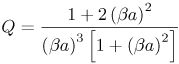
|
EAN: 2147483647
Pages: 110