4.3 EMV(TM) file system
4.3 EMV ¢ file system
The file organization in an EMV ¢ ICC is derived from the ISO/IEC 7816-4 [10] and is described both in Part II of Book 1 [1] and in Part I of Book 3 [3] of the EMV 2000 specifications. Figure 3.11 already presented a high level view of the EMV ¢ file system. We focus now on details concerning the data structures associated with EMV ¢ files. The terminal sees the EMV ¢ file system as a tree structure, having either ADF(s) or DDF(s) as branches.
4.3.1 ADFs
Logically, an ADF (as introduced in Section 3.4.2 and illustrated in Figure 3.11) encapsulates all the data files related to a card application. These data files are referred to as AEF(s) (see Section 3.4.1). Since an ADF is the entry point to one or several AEF(s) related to only one card application, it can be considered that an ADF ensures the separation between card applications.
Structurally, an ADF represents a DF as defined in the ISO/IEC 7816-4 [10], whose content consists of a File Control Information (FCI) Template, identified with the tag 6F. This template is context specific, and when it refers to an ADF it contains data objects as presented in Figure 4.3 (according to Table 40 in Book 1 [1]).
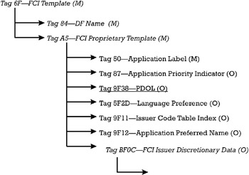
Figure 4.3: FCI of an ADF.
In this figure, a data element marked M is mandatory for inclusion in the template, while a data element marked O may be optionally included in the template.
4.3.1.1 The meaning of data elements in the FCI of the ADF
The subsequent paragraphs explain the meaning of the data elements encoded in the FCI of an ADF.
DF Name (tag 84) This mandatory data element represented on 5 to 16 bytes in a binary format stores the name of the DF that organizes the ADF. The terminal uses this element for referencing by the DF name the ADF (see Section 3.2.2).
The value of the DF name field can be the AID of the payment application contained in that ADF. The structure of the AID is defined in the ISO 7816-5 [11] as follows :
-
A RID on 5 bytes, unique to an application provider and assigned by a specialized agency, which guarantees the uniqueness of the RID;
-
The PIX, which is an optional field of up to 11 bytes assigned by the application provider to distinguish among several of its card application products. The PIX is unique only with respect to a RID and need not be unique across different RID(s).
Application Label (tag 50) This is a mandatory data element encoded as an alphanumeric string of 1 to 16 characters , which represents a name related with the AID of the card application in the ADF. It is defined in ISO 7816-5 [11]. The card application provider specifies the Application Label for displaying it at the man-machine interface of the terminal at the point of service. The Application Label is usually the trademark of the payment product.
Application Preferred Name (tag 9F12) This is an optional data element encoded as an alphanumeric string of 1 to 16 characters, which can provide a supplementary name for qualifying the card application in the ADF at the man-machine interface. For the same Application Label corresponding to a trademark belonging to a card association, different alphanumeric strings could be attached depending on a preferred alphabet used by the card issuer in a certain country.
Issuer Code Table Index (tag 9F11) This is an optional data element indicating the code table of an alphabet (according to ISO 8859 [12]) used for displaying the characters in the alphanumeric string Application Preferred Name. If the tag 9F12 is present in the FCI, then tag 9F11 should be also present.
Language Preference (tag 5F2D) This is an optional data element encoded as one to four alphanumeric strings of two characters each, indicating to the terminal a list of one to four language codes. Each language code is encoded according to ISO 639 [13]. These codes indicate the languages and their priority that the terminal should use at the man-machine interface for displaying messages to the cardholder.
Application Priority Indicator (tag 87) This is an optional data element encoded binary on 1 byte that indicates the priority given by the issuer (eventually tacking into account the cardholder's payment behavior) to the card application in this ADF compared to other card applications stored in the same card in other ADF(s). This priority indicator helps the terminal to establish the order of preference of card applications when displaying them at the terminal. This lets the cardholder choose the means of payment for a transaction according to its payment behavior.
The priority rank granted to the card application is specified in the bits b4 to b1. The value 1 indicates the highest priority, while 15 indicates the lowest priority. A value of 0 indicates that the ADF has no priority assigned. The bits b7 to b5 are RFU. Bit b8 specifies whether the explicit confirmation of the cardholder is needed for the selection of the card application in that ADF (b8 = 1) or not (b8 = 0).
Processing Options Data Object List (tag 9F38) The Processing Options Data Object List (PDOL) is an optional data element of the type DOL. The principles of working with a DOL were explained in Section 3.4.3.
The PDOL contains the list of tag-length identifiers of those data elements that the card application (contained in the ADF) would need to obtain from the terminal. These data elements help the card application to figure out its optimal behavior with respect to the business environment present at the point of service.
For example, the PDOL could include the tag-length identifiers of the Amount, Authorized (Binary) (tag 81) and Terminal Type (tag 9F35) data elements for optimally choosing the AIP that is returned in the response to the GET PROCESSING OPTIONS command (the details will follow in Chapter 6). In this case, the PDOL in the File Control Information (FCI) Template can be encoded as outlined in Figure 4.4.
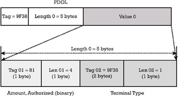
Figure 4.4: Example of a PDOL encoding.
An example of a rationale performed by the card based on the content of the data elements required in the PDOL and received from the terminal can be resumed as follows. If Amount, Authorized is below a floor limit and the Terminal Type is "Unattended, Offline Only, Controlled by the Financial Institution" then the AIP should state the inclusion of at least "Offline static data authentication is supported" card authentication in the transaction's profile.
FCI Issuer Discretionary Data (tag BF0C) This is an optional template that can store some data elements specifically defined by the issuer. For example, a data element in this template could be a key identifier of a secret key present in the card application. This key can be used by a specialized terminal of the issuer for authenticating to the card. This specialized terminal allows administrative card management operations. After correct authentication, the specialized terminal obtains the administrator rights for updating sensitive data files in the card application.
Other examples of data elements that can be contained in this template are data elements specifying the manufacturing environment (like the identifier of the card manufacturer), the type of integrated circuit used in the card, the version of the ROM mask, and the version of the operating system.
4.3.1.2 ADF and direct application selection service
The selection of an ADF allows access to the logical structure of a card application hosted in that ADF. Following its selection, the ADF returns the FCI template to the terminal.
Considering the application selection service, an EMV ¢ card in a multiapplication environment shall be able to respond positively to a direct application selection performed by a SELECT command specifying the AID as the file name.
The C-APDU of the SELECT command is given in Table 4.1 (according to Table 35 in Book 1 [1]).
| Code | Value |
|---|---|
| CLA | 00 (Interindustry command as defined in ISO 7816-4 [10]) |
| INS | A4 |
| P1 | Reference control parameter (according to Table 36 in Book 1 [1]) It accepts only one single value, 04, corresponding to "select by name" (i.e., referencing by the DF name according to the ISO/IEC 7816-4 [10]) |
| P2 | Selection options (According to Table 37 in Book 1 [1]) |
| Lc | 05h “10h |
| Data | File Name |
| Le | 00 |
The data field returned in the R-APDU of the SELECT command contains the FCI of the ADF (as schematized in Figure 4.3) and the status words SW1 SW2 = 9000, if the command executed successfully.
4.3.1.3 More on partial name selection
The support of the ICC for partial name selection is optional in EMV ¢ , but if it is supported the rules to be observed are listed in Section 7.3.5 of Book 1[1]. To explain the partial name selection mechanism we refer to the example presented in Figure 4.5.
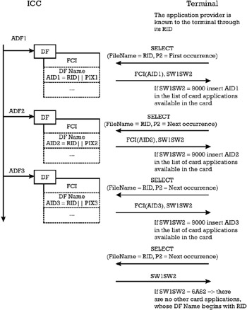
Figure 4.5: Partial name selection mechanism.
In this example the file structure of an EMV ¢ card contains three ADF files, hosting different card applications coming from the same application provider. Three different application identifiers AID1, AID2, and AID3 represent the DF name field in the FCI of ADF1, ADF2, and ADF3, respectively. They have in common the first 5 bytes, which represent the RID of the application provider, but each of the AID is qualified with a different PIX. Thus, the values of the AID(s) are AID1 = RID PIX1, AID1 = RID PIX2, and AID3 = RID PIX3. The terminal does not know the AID of all the card applications proposed by that application provider, but it knows its RID. In order to retrieve from the card all the card applications of the application provider, the terminal and the card perform the following steps:
-
Step 1: The terminal sends a SELECT command to the ICC with file name = RID and P2 = 00h, which means "First occurrence". The parameter Lc = 5, since the RID has 5 bytes. After receiving the command, if the ICC supports the partial name selection mechanism, it will send back the response containing SW1SW2 = 9000 and the FCI of ADF1. From this FCI the terminal can find out the complete application identifier AID1 of the first card application. The card internally marks the ADF1 as "already selected".
-
Step 2: The terminal repeats the previous SELECT command, with the same file name but with a different P2, which is set now to the value 02h, which means "Next occurrence". After receiving the command, the card selects a different DF file matching the partial name RID. This file is ADF2. The terminal learns the AID2 of the second card application. The card internally marks ADF2 as "already selected".
-
Step 3: The terminal repeats the previous SELECT command, with the same file name and with the same P2 ("Next occurrence"). After receiving the command, the card selects a different DF file than in the previous two steps matching the partial name RID. This file is ADF3, since the other two ADF(s) have already been marked as selected. The terminal learns the AID3 of the last card application. The card internally marks ADF3 as "already selected".
-
Step 4: Since the terminal does not know how many different AID(s) exist related to the application provider and how many of the corresponding card applications are personalized in the ICC, it will send once more the SELECT command with the same parameters as in Step 3. This time the card checks the partial name with all the ADF(s), but since they have been already marked as selected, the card shall send only SW1SW2 = 6A82 (file not found). These status words will inform the terminal not to issue a new SELECT command with the same file name.
The direct application selection service and the partial name selection mechanism are the basis of the application selection procedure presented in Section 4.4.2.
4.3.2 AEFs
The AEF(s) (as introduced in Section 3.4.1 and illustrated in Figure 3.11) are the effective containers of the data elements needed by a card application hosted in an ADF. An AEF is mapped to an elementary file (EF) as defined in ISO 7816-4 [10] and is never used as an entry point to another file.
After an ADF is selected, all the AEF(s) encapsulated in that ADF can be referenced through their SFI (see also Section 3.2.2). Any AEF within a given card application is referred by an SFI in the range of 1 to 30. The SFI shall be unique within a card application.
4.3.2.1 AEF with SFI in the range of 1 to 10
The AEF(s) addressed with an SFI in the range of 1 to 10 contain only data elements not interpreted by the card application in its internal processing (i.e., data to be used by the terminal exclusively). From this point of view an AEF in this range can be seen as a working EF. The content of these AEF(s) must be readable unconditionally by the terminal, and for updating they have access conditions to be fulfilled by an administrator of the card issuer from a specialized terminal.
The structure of an AEF in this range can be assimilated with a linear fix file or linear variable file (see Section 3.2.2) containing one or multiple records, each addressed by a record number. Each record is coded as a constructed data object referred to as the AEF Data Template with tag 70, which is an EMV ¢ proprietary tag. The length field of the AEF Data Template indicates the total length of the data objects encapsulated in the template. This length would be no bigger than 251 bytes. For interoperability reasons, the AEF Data Template shall encapsulate in its value field only data objects accepted by the EMV ¢ debit/credit application, as defined in Book 3 [3], Annex A, Table A-1. The mapping of these EMV ¢ data objects in AEF Data Templates and the grouping of these templates in AEF(s) are left to the discretion of the issuer.
The SFI can be used as a file handler in the READ RECORD commands. These commands allow the terminal at the point of service to read the public content of the AEF(s) in the selected ADF.
The C-APDU of the READ RECORD command is given in Table 4.2 (according to Table 33 in Book 1 [1] and Table I-21 in Book 3 [3]).
| Code | Value |
|---|---|
| CLA | 00 (Interindustry command as defined in ISO 7816-4 [10]) |
| INS | B2 |
| P1 | Record number |
| P2 | Reference control parameter (according to Table 34 in Book 1 [1] and Table I-22 in Book 3 [3]) b8 “ b4 (5 bits): it encodes the SFI of the AEF whose record, with the number indicated in P1, must be read b3 b2 b1 = 100: it indicates that P1 has the meaning of a record number |
| Lc | Not present |
| Data | Not present |
| Le | 00 |
The data field returned in the R-APDU of a successfully executed READ RECORD command contains the record that is actually read from the AEF, which is encoded within an AEF Data Template. The R-APDU also returns the status words SW1 SW2 = 9000 if the command is successfully executed.
For the purpose of an EMV ¢ debit/credit card application that conforms to Book 3 [3], there is another data element that should be attached to an ADF beside the FCI. This data element is called the AFL (tag 94), providing a list of all the AEF(s) accessible to the terminal, indicating for each AEF its location (SFI) and the range of records in that AEF that are relevant for a given application. More details on the AFL will be provided in Section 6.2.3.
4.3.2.2 AEF with SFI in the range of 11 to 20 and 21 to 30
AEF(s) with a SFI in the range of 11 to 20 are reserved for grouping proprietary data elements of an EMV ¢ debit/credit application as specified by the individual payment system operators developing an EMV ¢ payment card product. Application elementary files with a SFI in the range of 21 to 30 are reserved for grouping proprietary data elements of an EMV ¢ debit/credit application, which are defined by the issuer for its own needs.
4.3.2.3 AEF storing the directory file of a DDF or PSE
While an AEF as presented above can be seen as a data container for EMV ¢ card applications, it can also store a directory file. In this case the AEF encodes the directory entries of a DDF or of a PSE. All the details related to a DDF, a PSE, and their directory structure implemented as an AEF are provided in Sections 4.3.3 and 4.3.4 below.
4.3.3 Directory definition files
Logically, a DDF (as introduced in Section 3.4.2 and illustrated in Figure 3.11) provides an entry point to one or more ADF(s) and to one or more hierarchically inferior DDF(s). To this end the DDF introduces a directory, which lists a separate entry for each ADF and (hierarchically inferior) DDF to which the current DDF offers access.
4.3.3.1 Directory file, directory entry, and directory structure
The implementation of a directory is performed with a directory file. The directory file is an AEF referenced with an SFI in the range of 1 to 10 containing one or several records. Each record is encoded as an AEF Data Template (see Section 4.3.2). Remember that an AEF attached to an ADF may contain any data objects accepted by the EMV ¢ debit/credit application, as defined in Book 3 [3], Annex A, Table A-1. In opposition , an AEF Data Template in a directory file encapsulates in its value field just one or more application templates (tag 61), according to ISO/IEC 7816-5 [11]. In its turn , each Application Template encodes only one directory entry for either an ADF or a DDF.
The encoding of a directory entry is different for an ADF than for a DDF:
-
According to Table 43 in Book 1 [1], an ADF directory entry contains two mandatory data elements. The first element is the ADF name (tag 4F), encoded on 5 to 16 bytes in binary format, which contains the AID of the card application stored in the corresponding ADF. The second element is the Application Label of the card application stored in the ADF. The meaning of this data element was explained in Section 4.3.1. Optionally, the ADF directory entry may encapsulate the Application Preferred Name and the Application Priority Indicator, which were also introduced in Section 4.3.1.
-
According to Table 42 in Book 1 [1], a DDF directory entry contains the mandatory data element DDF Name (tag 9D) encoded on 5 to 16 bytes in binary format.
Both the ADF directory entry and the DDF directory entry can incorporate a Directory Discretionary Template (tag 73), which may encode some proprietary data objects meaningful for the organization managing the ADF or DDF.
Figure 4.6 exemplifies an AEF Data Template of a directory file, which introduces two ADF(s) and one hierarchically inferior DDF.
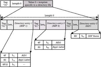
Figure 4.6: Example of an AEF Data Template in a directory file.
The directory structure of a DDF consists of its own directory and the directories introduced by all the hierarchically inferior DDF(s) to which this DDF offers access.
4.3.3.2 FCI of a DDF
Structurally, a DDF represents a DF as defined in the ISO/IEC 7816-4 [10], whose content consists of an FCI template. This template is context specific, and when it refers to a DDF, it contains data objects as presented in Figure 4.7 (according to Table 39 in Book1 [1]).
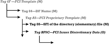
Figure 4.7: FCI of a DDF.
Some explanations of the data elements in the FCI of the DDF are provided below.
-
The FCI of the DDF includes the DF Name field. This mandatory data element is represented on 5 to 16 bytes in binary format and stores the name of the DF that organizes the DDF.
-
Since the DDF introduces a directory file implemented in an AEF, the FCI of the DDF must include the SFI reference of this directory file. This SFI reference is mapped to the data element SFI of the directory elementary file, with tag 88. This element is encoded binary on 1 byte with the three high-order bits set to zero.
-
Optionally, the FCI of the DDF may also include the FCI Issuer Discretionary Data template, which encapsulates one or more additional private data elements from the application provider that manages the applications grouped under the DDF, from the card issuer, or from the IC card supplier.
The terminal uses the DF Name element for referencing by the DF name the DDF (see Section 3.2.2). This can be achieved with a SELECT command as introduced in Section 4.3.1. In case of complete name selection, the file name parameter of the SELECT command is the complete DF Name, while in case of partial name selection the file name is the DF Name right truncated to at least 5 bytes. The response of the SELECT command provides the FCI of the DDF, with the complete DF Name and the SFI of the AEF that stores the directory file.
4.3.3.3 Directory structure and indirect application selection service
The directory structure allows the implementation of the indirect application selection service . Through this service the terminal can learn by itself all card applications and groups of card applications to which the DDF offers access. The condition is that the terminal knows only the reference to this DDF.
Assume that a DDF introduces a directory file, implemented as an AEF with SFI = 2. This directory file contains only one record, encapsulating the AEF Data Template that was exemplified in Figure 4.6. Admit also that the DF name of the DDF is encoded as an ASCII string "DDFName". The terminal, which knows only the DF name of the DDF, can implement the indirect application selection service with the following sequence of commands:
-
Step 1: The terminal sends a SELECT command to the ICC with file name = "DDFName" and P2 = 00h, which means "First occurrence". The parameter Lc = 7, since the file name can be encoded on 7 bytes using the ASCII representation. After receiving the command, the ICC will send back the response containing SW1SW2 = 9000 and the FCI of the DDF. From this FCI the terminal can find out the SFI of the directory file introduced by the DDF, which is 2.
-
Step 2: The terminal sends a READ RECORD command to the ICC with P1 = 1 (indicating the first record) and P2 = 14h (the SFI = 2 is encoded as 00010 in the leftmost 5 bits of P2, and 100 in the rightmost 3 bits of P2). The card returns the response containing the status words SW1SW2 = 9000 and the AEF Data Template exemplified in Figure 4.6.
-
Step 3: The terminal once again sends a READ RECORD command to the ICC, since it does not know how many records are encoded in the directory file. The command is sent with P1 = 2 (indicating the second record) and P2 = 14h. The card returns the response containing only the status words SW1SW2 = 6A83, "Wrong parameters(s) P1 P2; record not found". Thus, the terminal knows that the directory file was composed of one single record.
-
Step 4: The terminal parses the AEF Data Template in three distinct application templates (under the tag 61), each containing a distinct directory entry.
-
The first and the second application templates are ADF directory entries, since they start with tag 4F. When parsing the first directory entry, the terminal can learn the AID of the first card application introduced by the DDF (namely AID1), its application name, and even the application preferred name. However, there is no Application Priority Indicator attached to this first application. Parsing the second entry, the terminal learns the AID of the second card application introduced by the DDF (namely AID2), as well as its Application Label. The terminal has now enough information to perform the selection of any of these two applications.
-
The third Application Template is a DDF directory entry, since it starts with a tag 9D. The terminal learns the DDF name of the only hierarchically inferior DDF introduced by the current DDF, which can be assumed to be the identifier "DDF1Name".
-
-
Step 5: The terminal sends a SELECT command to the ICC with file name = "DDF1Name" and P2 = 00h, which means "First occurrence". The parameter Lc = 8, since the identifier can be encoded on 8 bytes using the ASCII representation. After receiving the command, the ICC will send back the response containing SW1SW2 = 9000 and the FCI of the DDF1. From this FCI the terminal can find out the SFI of the directory file introduced by the DDF1. From now on the terminal can appropriately repeat the sequence consisting of step 2 to step 4 to recursively construct the whole directory structure of the initial DDF.
The protocol above is outlined in Figure 4.8. The directory structure and its use for the indirect application selection service are the basis of the application selection procedure presented in Section 4.4.1.
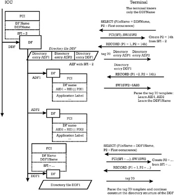
Figure 4.8: Directory structure and indirect application selection service.
4.3.4 Payment system environment
Logically, a PSE is a DDF, whose DF name is given the value 1PAY.SYS.DDF01. The PSE represents a predefined entry point to a set of payment card applications or groups of payment card applications. An application provider, who can be a payment system operator or a card association, can manage a group . The presence of the PSE in the ICC is optional, but when it is present it should comply with the rules stated in Section 8.2.2 of Book 1 [1].
As with any DDF, the PSE is mapped onto a DF in the ICC, which could or could not be the master file (MF). When the PSE is organized in the MF, the multiapplication ICC can be considered as a payment dedicated ICC. If the PSE is organized in a DF under the MF, the ICC can store card applications outside the PSE. These card applications can provide different functionality than payment.
The content of the PSE consists of an FCI template. This template is context specific, and when it refers to a PSE, it contains data objects as presented in Figure 4.9 (according to Table 38 in Book 1 [1]).
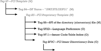
Figure 4.9: FCI of the PSE.
Some explanations on the data elements in the FCI of the PSE are provided below.
-
The FCI of the PSE includes the DF name field, which has the predefined value 1PAY.SYS.DDF01.
-
Since the PSE introduces the payment system directory file, also referred to as the DIR file, its FCI must include the SFI reference of this directory file. This SFI reference is encoded in the same way as explained for a DDF.
-
The FCI of the PSE may optionally include the Language Preference and the Issuer Code Table Index, with the same meaning as that explained in connection with an ADF. When these elements are present in the FCI of the PSE, they should also exist in the FCI of each ADF encompassed in the PSE, and they should have the same value. This is because the terminal could use these elements from either location. When the terminal implements the indirect application selection service, it will read these elements from the FCI of the PSE; when using the direct application selection service, it will read these elements from the FCI of the ADF directly selected.
-
Optionally, the FCI of the PSE may also include the FCI Issuer Discretionary Data template, with a similar meaning as for a DDF.
The terminal uses the identifier 1PAY.SYS.DDF01 for referencing by the DF name the PSE. This can be achieved with a SELECT command as introduced in Section 4.3.1 with complete name selection. Thus, the file name parameter of the SELECT command is the identifier 1PAY.SYS.DDF01 and P2 is set to "First or only occurrence". The response of the SELECT command provides the FCI of the PSE, with the SFI of the AEF that stores the DIR file.
The directory structure of the PSE consists of the DIR file at the PSE level and all the additional directory files introduced by DDF(s), which are subordinated to the PSE.
The ADF and DDF directory entries in the DIR file correspond to ADF(s) and DDF(s) that are formatted according to Book 1 [1]. An application defined by an ADF, which is mentioned in the DIR file, might be an EMV ¢ debit/credit payment application according to Book 3 [3]. However, there could be ADF(s) that define payment applications implementing payment methods other than EMV ¢ debit/credit (e.g., an electronic purse with CEPS, or a loyalty scheme).
The directory structure of the PSE will include only those payment card applications that the issuer wants to be visible in an interoperable environment. Thus, there could be card applications whose ADF is not included in any directory file in the directory structure, and which could be selected only by a proprietary terminal that is aware about their existence in the ICC card.
EAN: 2147483647
Pages: 131