Sequence Diagrams
| I l @ ve RuBoard |
| A sequence diagram shows object interactions arranged in time sequence. It depicts the objects and classes involved in the scenario and the sequence of messages exchanged between the objects needed to carry out the functionality of the scenario. Sequence diagrams typically are associated with use case realizations in the Logical View of the system under development. In the UML, an object in a sequence diagram is drawn as a rectangle containing the name of the object, underlined . An object can be named in one of three ways: the object name, the object name and its class, or just the class name (anonymous object). The three ways of naming an object are shown in Figure 5-5. Figure 5-5. Naming Objects in a Sequence Diagram Object names can be specific (e.g., Algebra 101, Section 1) or they can be general (e.g., a course offering). Often, an anonymous object (class name only) may be used to represent any object in the class. Each object also has its timeline represented by a dashed line below the object. Messages between objects are represented by arrows that point from the client (sender of the message) to the supplier (receiver of the message). The UML notation for objects and messages in a sequence diagram is shown in Figure 5-6. CREATING A SEQUENCE DIAGRAM IN RATIONAL ROSE
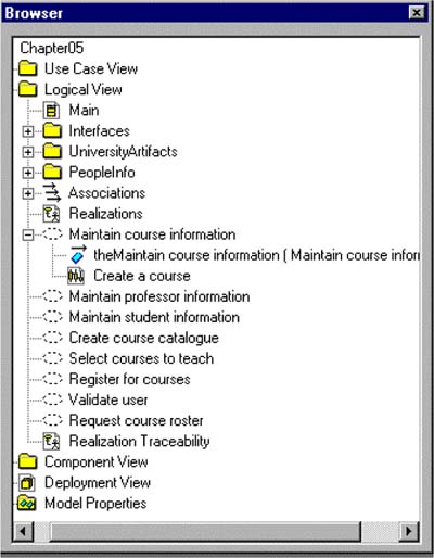
Figure 5-6. UML Notation for Objects and Messages in a Sequence Diagram The browser view of a sequence diagram is shown in Figure 5-7. CREATING OBJECTS AND MESSAGES IN SEQUENCE DIAGRAMS IN RATIONAL ROSE
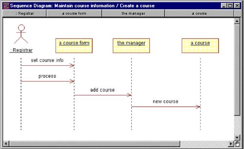
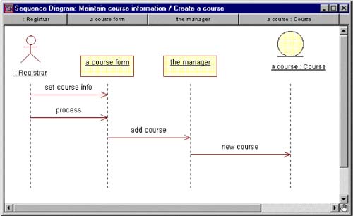
Figure 5-7. Browser View of a Sequence Diagram The sequence diagram for the Create a Course scenario is shown in Figure 5-8. ASSIGNING OBJECTS IN A SEQUENCE DIAGRAM TO CLASSES IN RATIONAL ROSE
Figure 5-8. Sequence Diagram A sequence diagram with the object "a course" assigned to the Course class is shown in Figure 5-9. Figure 5-9. Sequence Diagram with an Object Assigned to a Class |
| I l @ ve RuBoard |
EAN: 2147483647
Pages: 134
- Chapter I e-Search: A Conceptual Framework of Online Consumer Behavior
- Chapter IV How Consumers Think About Interactive Aspects of Web Advertising
- Chapter VIII Personalization Systems and Their Deployment as Web Site Interface Design Decisions
- Chapter XII Web Design and E-Commerce
- Chapter XVII Internet Markets and E-Loyalty