Deploying Your Application
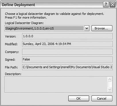
| The intent of modeling the logical infrastructure is to avoid problems that might arise during deployment of an application. It can be extremely frustrating to get your application built and tested in one environment only to see it fail to deploy in the production environment. Often these issues are not found until late in the project and end up causing great delays and other headaches. If you've been doing development for a while, you've undoubtedly come across the statement "Deploy early, deploy often." This adage is in direct response to those who have experienced these headaches. You can be thankful that the Deployment Designer was built to try to avoid these types of issues. It allows you to deploy as often as you like. Deployment DiagramTeam Architect ships with the Deployment Designer. This tool ties together the application and the logical datacenter diagrams. With it, you can use an application diagram to do a test deployment against your logical infrastructure. This test deployment will show where the application should run smoothly when you deploy it and where errors exist. To start, you need to create a deployment diagram (.dd). You can do so from an existing application diagram. With it open, you can use the Diagram menu or the context menu and choose the Define Deployment option. Selecting this menu item brings up the Define Deployment dialog box (see Figure 21.23). From here, you select a logical datacenter diagram that represents the environment to which you want to test deploy. Figure 21.23. Define Deployment dialog box. Visual Studio then brings up the deployment diagram. Remember, it is meant to be a marriage between your logical datacenter and application diagrams. Figure 21.24 shows an example. Notice that the diagram itself looks mostly like your infrastructure. The reason is that you are deploying your application into this diagram. Each server in the infrastructure has a box below it to which you can add an application. The applications from the application diagram are listed in the tree (System View) on the left side of the figure. Finally, notice that each application is added to its respective server. Figure 21.24. The deployment diagram.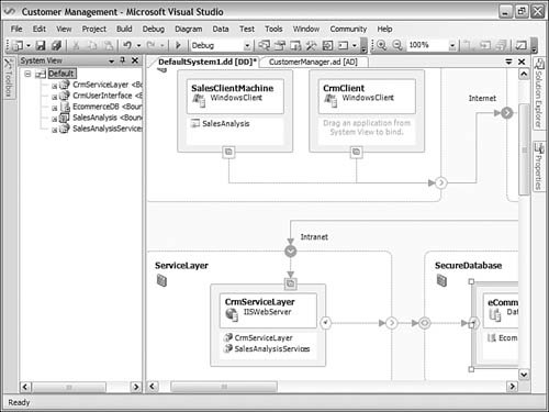 Validate DeploymentThe next step is to test the deployment. Some testing occurs when adding applications to the servers. The Deployment Designer will not allow you to add applications if you are breaking a hard rule in the deployment. For example, you cannot add a web application to the database server. To validate the deployment, you choose the Validate Diagram option from the diagram or context menu. This checks the configuration of your applications against all the pieces of the infrastructure diagram. It then generates a set of warnings and errors for you to review. Figure 21.25 shows the results of the example. You can see there were no errors but plenty of warnings to work on. Figure 21.25. Warnings generated from the validate diagram.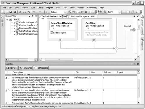 Deployment ReportYou can also generate a report that details your deployment. This lengthy document indicates every aspect of the application, datacenter, and deployment. You can set a few options for generating the report. For example, you can indicate whether you want to see copies of the diagrams in the report. You set these options from the Properties window of the deployment diagram itself. To access the report generation tool, you use the Diagram or context menu and choose the Generate Deployment Report option. Selecting this menu item creates the detailed report. Figure 21.26 shows a sample portion of the report. The contents of this report are all inclusive. You may prefer to pull a few sections out and paste them into a smaller report for archiving. Figure 21.26. The deployment report.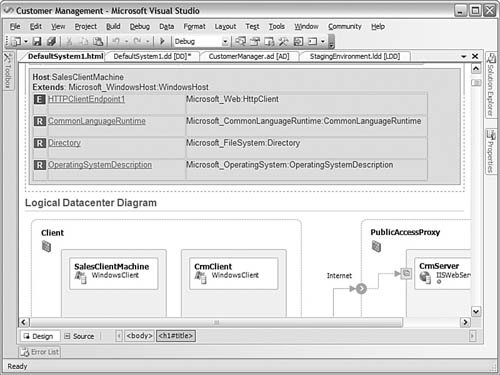 |
EAN: 2147483647
Pages: 195