Section 8.1. Behavioral State Machines
8.1. Behavioral State MachinesState machines represent the behavior of a piece of a system using graph notation. A state machine is shown using the basic rectangle notation, with the name of the state machine shown in the top compartment. The outside rectangle is often omitted on state machine diagrams that show only a single state machine. The metaclass is simply state machine. Figure 8-1 shows a simple state machine modeling a soda machine. Figure 8-1. A basic state machine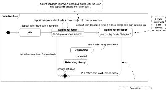 A state machine is often associated with a classifier in the larger UML modelfor example, a class or subsystem. However, UML doesn't define a specific notation to show this relationship. One possible notation is to use a note labeled with the name of the state machine and linked to the classifier. Figure 8-2 shows an example that uses a note to link a state machine to a classifier. Figure 8-2. Example of linking a state machine to a classifier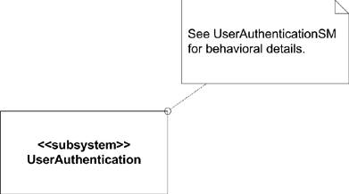 You can model the behavior of the classifier using states, pseudostates, activities, and transitions. If a state machine is used to model the behavior of an operation (see "Operations" in Chapter 2), the state machine must have parameters that match the operation's parameters. These can be used in any transition or state as needed. Transitions between states occur when events are dispatched (see "Dispatch"). As the state machine executes, activities are run based upon the transition, entry into a state, and so on (see "Activities"). Each state machine has a set of connection points that define the external interface to the state machine. These connection points must be either Entry or Exit pseudostates. |
EAN: 2147483647
Pages: 132